
Introduction
When selecting a miniature circuit breaker (MCB) for an electrical installation, most engineers focus on the rated current—but there’s a critical variable that can drastically affect performance: ambient temperature. An MCB rated at 32A won’t necessarily carry 32A safely in all environments. In fact, at elevated temperatures, that same MCB might trip at just 28A or lower, leading to unexpected shutdowns and system failures.
Understanding MCB ambient temperature ratings and derating factors is essential for electrical professionals who need to ensure reliable protection in diverse operating conditions. Whether you’re designing a control panel for a desert climate, specifying breakers for an enclosed machinery cabinet, or troubleshooting nuisance tripping issues, temperature considerations play a defining role.
This comprehensive guide examines how ambient temperature affects MCB performance, explains the derating calculation methodology, and provides practical guidance for real-world installations. By the end, you’ll understand how to properly select and apply MCBs across varying thermal environments, ensuring both safety and operational reliability.
Understanding MCB Temperature Ratings
The Standard Reference Temperature
Every MCB is calibrated and tested at a specific reference ambient temperature, which serves as the baseline for its nominal current rating. According to IEC 60898-1—the international standard governing MCBs for household and similar installations—this reference temperature is 30°C (86°F). At this precise temperature, an MCB will perform according to its nameplate rating.
For industrial applications requiring more robust circuit breakers, such as molded case circuit breakers (MCCBs) governed by IEC 60947-2, the standard reference temperature is typically 40°C (104°F). This higher baseline reflects the more demanding thermal environments common in industrial settings.
How MCBs Are Rated
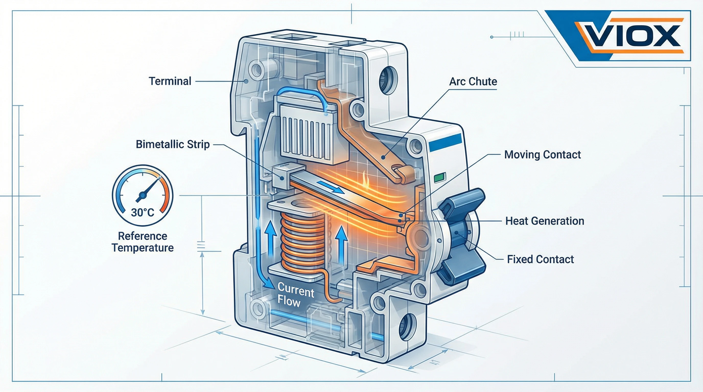
The rated current (In) marked on an MCB represents the maximum continuous current the device can carry indefinitely at the reference temperature without tripping. This rating is determined through rigorous testing where the MCB’s thermal trip element—typically a bimetallic strip—is calibrated to bend and activate the trip mechanism at specific overcurrent thresholds.
The bimetallic strip is the heart of an MCB’s overload protection. It consists of two different metals bonded together, each with a different coefficient of thermal expansion. When current flows through the strip, it generates heat. As temperature rises, the metals expand at different rates, causing the strip to bend. Once it bends sufficiently, it triggers the trip mechanism, disconnecting the circuit.
This elegant thermal-mechanical system works precisely at the calibrated reference temperature. However, it’s also inherently sensitive to the ambient temperature surrounding the MCB—which is where derating becomes critical.
The Temperature Range Limitation
While MCBs are typically rated for operation within a range of -20°C to +70°C, their ability to carry the rated current diminishes significantly as ambient temperature increases beyond the reference point. Conversely, in colder environments below the reference temperature, an MCB may allow slightly higher current before tripping—though this is rarely a design consideration since the connected cables and equipment have their own temperature limitations.
How Ambient Temperature Affects MCB Performance
The Physics of Thermal Tripping
The relationship between ambient temperature and MCB performance is rooted in basic thermal physics. The bimetallic strip inside an MCB must reach a specific temperature to trip. This temperature is achieved through two heat sources: the heat generated by the current flowing through the strip (I²R heating) and the heat from the surrounding environment (ambient temperature).
When ambient temperature increases, the bimetallic strip starts from a higher baseline temperature. It therefore requires less additional heating from current flow to reach its trip point. In practical terms, this means the MCB will trip at a lower current than its rated value.
Consider an MCB rated at 32A at 30°C. If that same MCB operates in a 50°C environment, the bimetallic strip begins 20°C hotter than the calibration baseline. To reach the trip temperature, it needs less current-induced heating—perhaps tripping at only 29A or 30A instead of the rated 32A.
Current Capacity Reduction
As a general rule, for thermal-magnetic MCBs, the current-carrying capacity decreases by approximately 6-10% for every 10°C rise above the reference temperature. This isn’t a linear relationship across all temperature ranges, and it varies by manufacturer and product series, but it provides a useful estimation framework.
For example:
- An MCB at 40°C (10°C above the 30°C reference) might operate at roughly 94% of its rated capacity
- At 50°C (20°C above reference), capacity drops to approximately 88-90%
- At 60°C (30°C above reference), capacity may be reduced to 80-85%
Failure Modes from Inadequate Derating
When MCBs operate in higher ambient temperatures without proper derating consideration, two primary failure modes emerge:
Nuisance Tripping: The MCB trips during normal operation because the actual current, while within the nameplate rating, exceeds the temperature-adjusted capacity. This leads to unexpected downtime, productivity losses, and frustration for operators who see no apparent overload.
Premature Aging: If the MCB is consistently operated near its temperature-derated limit in a hot environment, the internal components experience accelerated thermal stress. This degrades the bimetallic strip calibration over time, reducing the device’s service life and potentially compromising protection reliability.
Both scenarios undermine the fundamental purpose of the MCB: reliable, predictable circuit protection.
Derating Factors Explained
What Is a Derating Factor?
A derating factor (also called a temperature correction factor or ambient temperature correction factor) is a multiplier applied to an MCB’s nominal rating to determine its effective current-carrying capacity at a specific ambient temperature. This factor is always less than or equal to 1.0 for temperatures at or above the reference temperature.
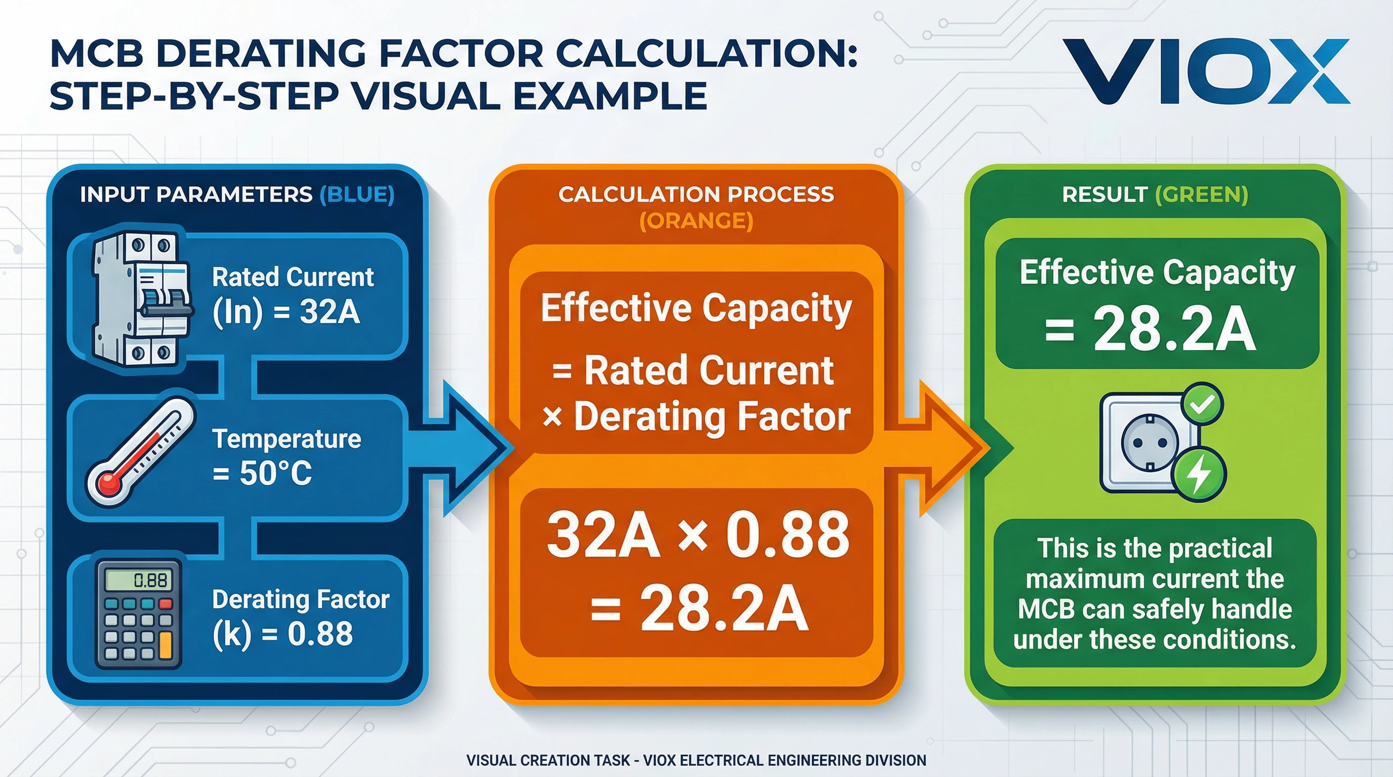
The mathematical relationship is straightforward:
Effective Current Capacity = Rated Current × Derating Factor
For example, if a 25A MCB has a derating factor of 0.88 at 50°C:
- Effective capacity = 25A × 0.88 = 22A
This means that in a 50°C environment, the MCB should not be loaded beyond 22A to ensure reliable operation without nuisance tripping.
How Derating Factors Are Determined
Derating factors are not theoretical calculations—they’re empirically derived through extensive testing by manufacturers. Each MCB product series undergoes thermal testing across a range of ambient temperatures to measure actual trip characteristics. The results are compiled into derating tables or curves specific to that product line.
This is why it’s critical to consult the manufacturer’s technical documentation rather than relying solely on generic industry rules of thumb. Different MCB designs, internal component layouts, and thermal management features can result in varying derating characteristics even for breakers with the same nominal rating.
The Derating Curve
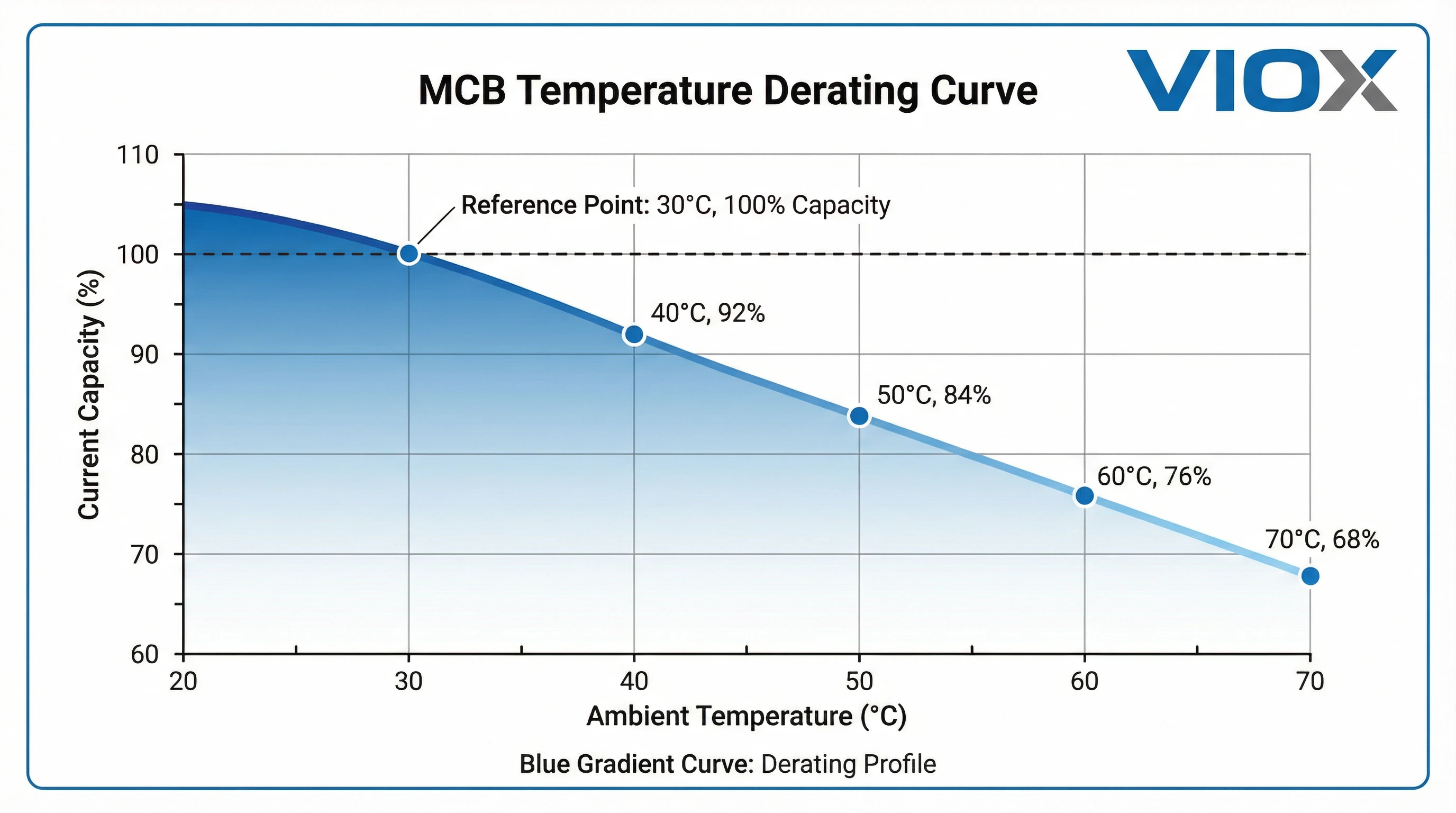
Manufacturers typically present derating information in two formats: tabular data and graphical curves. A derating curve plots ambient temperature on the X-axis against either the derating factor or the effective current capacity on the Y-axis.
These curves reveal important characteristics:
- The relationship is generally non-linear, with steeper capacity reduction at higher temperatures
- Some MCB designs show more gradual derating, while others drop off more sharply
- The curves may flatten at very high temperatures, approaching the MCB’s absolute maximum operating limit
Practical Calculation Examples
Example 1: Basic Derating
You need to install an MCB in a control panel where the internal ambient temperature reaches 55°C. The circuit requires continuous protection for a 30A load. The manufacturer’s data shows a derating factor of 0.85 at 55°C.
- Required MCB rating = Load Current ÷ Derating Factor
- Required MCB rating = 30A ÷ 0.85 = 35.3A
- Select the next standard size: 40A MCB
Example 2: Verification Approach
You’ve specified a 63A MCB for an application. The expected ambient is 60°C. The manufacturer’s table shows this MCB can carry 54A at 60°C (derating factor of approximately 0.86).
If your actual load is 58A:
- 58A > 54A (temperature-adjusted capacity)
- The 63A MCB is undersized for this application; upgrade to 80A
Example 3: Reverse Calculation
An existing installation uses a 32A MCB. Summer temperatures inside the electrical enclosure reach 65°C. Using a manufacturer derating factor of 0.78 at 65°C:
- Effective capacity = 32A × 0.78 = 25A
- Maximum safe continuous load: 25A
These examples demonstrate why temperature derating must be an integral part of MCB selection, not an afterthought.
Standard Derating Tables & Guidelines
Typical Derating Values
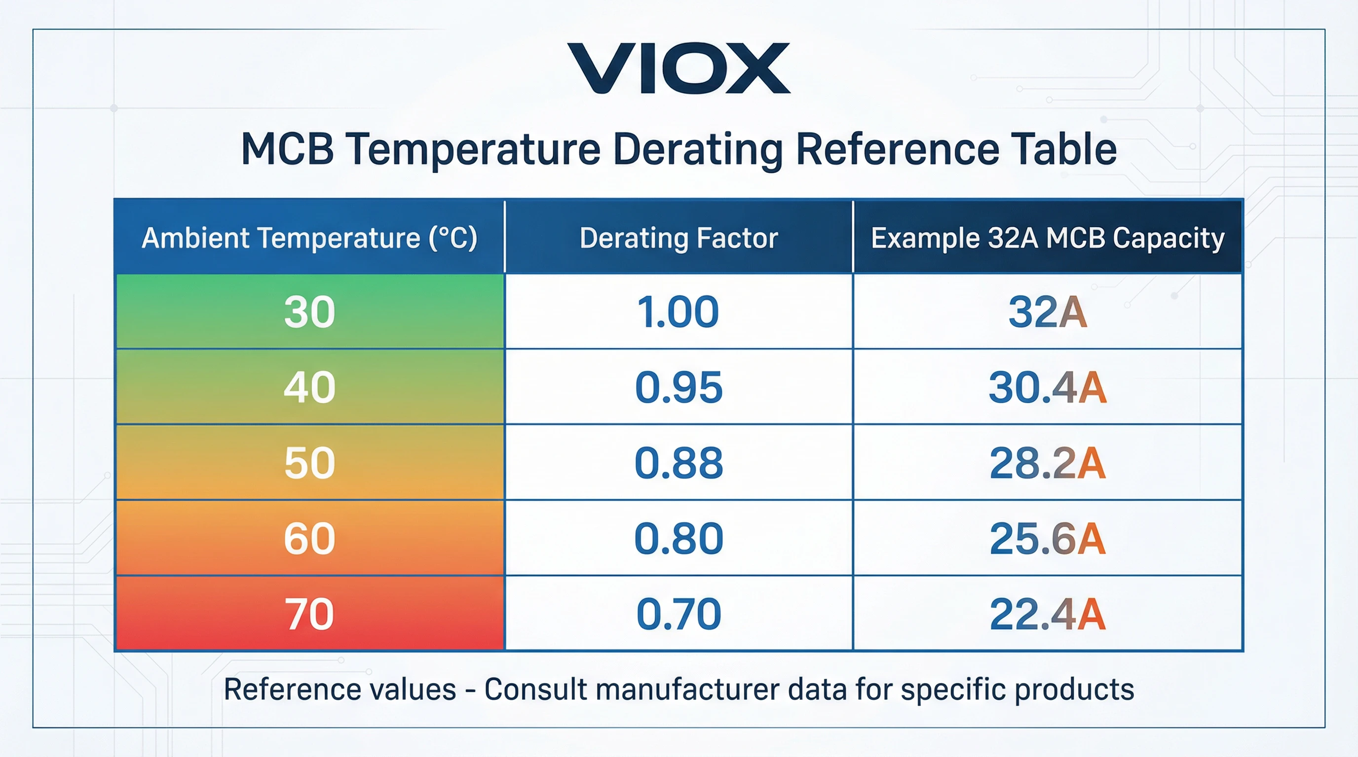
While specific derating factors vary by manufacturer and product line, industry data reveals consistent patterns. For thermal-magnetic MCBs calibrated at 30°C (per IEC 60898-1), typical derating factors are:
| Ambient Temperature | Typical Derating Factor | Example: 32A MCB Effective Capacity |
|---|---|---|
| 30°C (reference) | 1.00 | 32A |
| 40°C | 0.94 – 0.97 | 30A – 31A |
| 50°C | 0.88 – 0.95 | 28A – 30A |
| 60°C | 0.76 – 0.90 | 24A – 29A |
| 70°C | 0.64 – 0.85 | 20A – 27A |
For MCBs and MCCBs calibrated at 40°C (per IEC 60947-2), the baseline shifts accordingly:
| Ambient Temperature | Typical Derating Factor | Example: 100A MCCB Effective Capacity |
|---|---|---|
| 40°C (reference) | 1.00 | 100A |
| 50°C | 0.90 – 0.94 | 90A – 94A |
| 60°C | 0.80 – 0.87 | 80A – 87A |
| 70°C | 0.70 – 0.80 | 70A – 80A |
The ranges reflect variations among different manufacturers’ product designs. Premium MCB series with enhanced thermal management may show better performance at elevated temperatures.
Manufacturer-Specific Data
Leading manufacturers provide detailed derating information in their technical catalogs:
ABB S200 Series (30°C reference): For an 80A MCB, the maximum operating current at various temperatures is approximately 77.6A at 50°C, 75.2A at 60°C, and 72.8A at 70°C.
Schneider Electric Acti9 Series: A 160A thermal-magnetic breaker calibrated at 40°C shows effective capacities of 150A at 50°C, 140A at 60°C, and 130A at 70°C—demonstrating roughly 10A reduction per 10°C increment.
Eaton and Siemens: Both manufacturers emphasize the importance of consulting product-specific documentation, as derating characteristics vary significantly across their extensive MCB portfolios.
IEC Standards Guidance
IEC 60898-1 and IEC 60947-2 establish the testing protocols and reference temperatures but do not mandate specific derating values. Instead, manufacturers must provide this data based on type testing of their products. The standards require that MCBs operate safely across their specified temperature range, but performance degradation at temperature extremes is expected and must be accounted for in application engineering.
When to Apply More Conservative Factors
In certain scenarios, applying more conservative derating is prudent:
- Mission-critical applications where any nuisance trip has severe consequences
- Installations with poor temperature monitoring where actual ambient may exceed design assumptions
- Aging installations where MCB calibration may have drifted over years of service
- Environments with wide temperature fluctuations that stress the bimetallic strip through repeated thermal cycling
Practical Application & Installation Considerations
Defining Ambient Temperature in Real Installations
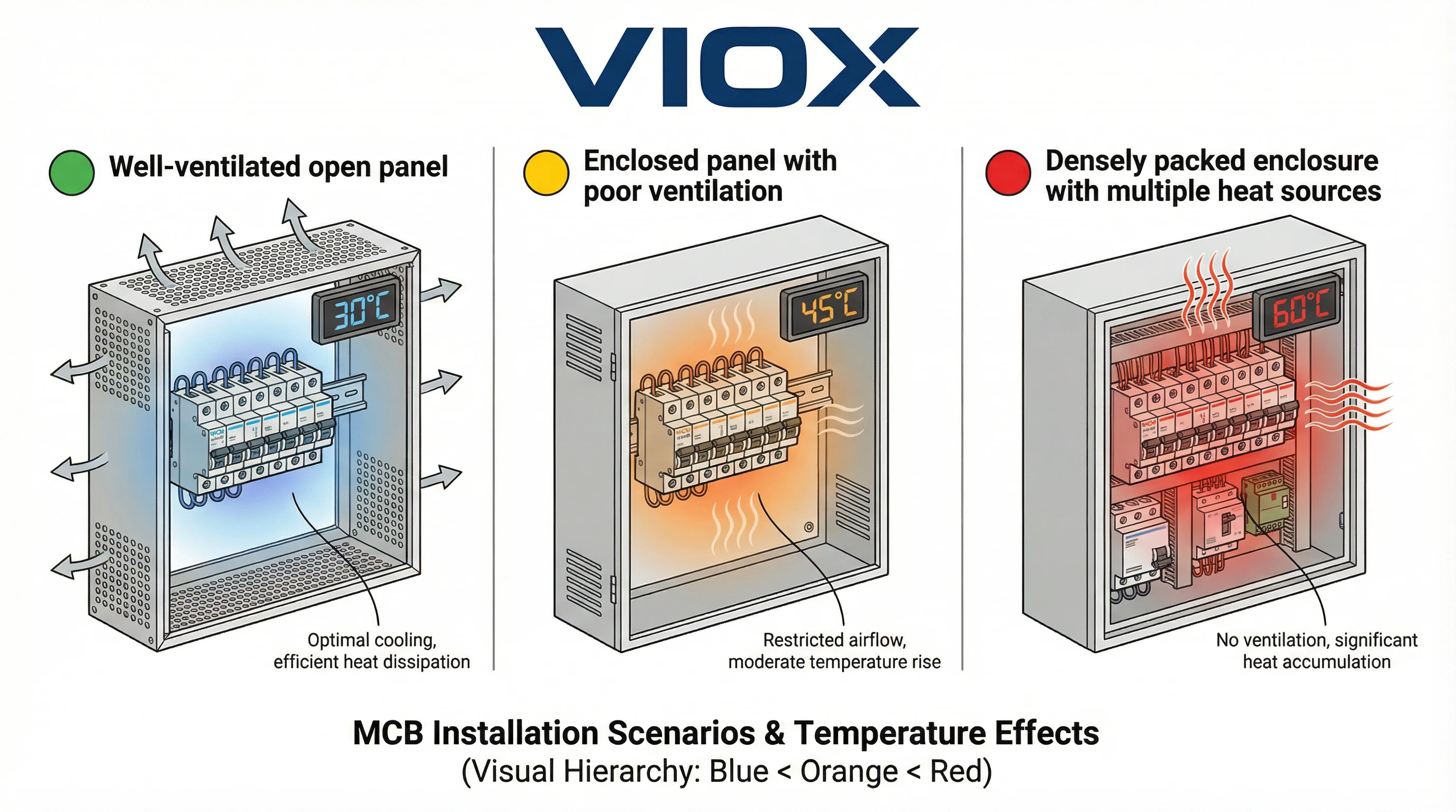
A critical point often misunderstood: ambient temperature for MCB derating purposes is not room temperature. It’s the temperature of the air immediately surrounding the MCB itself. In enclosed installations, this can be significantly higher than the general environment.
A control panel sitting in a 25°C air-conditioned room may have an internal temperature of 45°C or higher due to heat generated by other equipment, solar loading on the enclosure, or inadequate ventilation. Always measure or calculate the actual temperature inside the enclosure where the MCBs are mounted.
Enclosure Effects and Heat Accumulation
Electrical enclosures create localized hot zones. Heat sources include:
- Power supplies and transformers generating continuous heat
- VFDs (Variable Frequency Drives) with switching losses
- Contactors and relays with energized coils
- The MCBs themselves contributing I²R losses
In a densely packed panel without adequate ventilation, internal temperatures can exceed external ambient by 20-30°C. Ventilation fans, heat sinks, and proper spacing are essential mitigation strategies.
Grouping Factors and Multiple MCBs
When multiple MCBs are mounted side-by-side in close proximity, their combined thermal output creates mutual heating effects. This requires applying an additional grouping factor or arrangement factor on top of the ambient temperature derating.
For example, IEC 60947-2 recognizes that circuit breakers mounted in rows within an enclosure experience higher operating temperatures than isolated units. Some manufacturers provide specific guidance: a row of 3-6 adjacent MCBs might require an additional 5-10% derating beyond the temperature correction.
The cumulative effect can be substantial:
- Ambient temperature derating: 0.90 (at 50°C)
- Grouping factor: 0.95 (for 4 adjacent MCBs)
- Combined factor: 0.90 × 0.95 = 0.855
- A 32A MCB effectively becomes: 32A × 0.855 = 27.4A capacity
Ventilation and Thermal Management
Proper enclosure design significantly impacts MCB thermal performance:
Natural convection: Ensure adequate clearance above and below MCB rows. Hot air must escape from top vents while cooler air enters from below.
Forced ventilation: In high-density installations or hot environments, specify ventilation fans sized to maintain acceptable internal temperatures. A general guideline is to keep enclosure internal temperature within 10-15°C of external ambient.
Thermal barriers: Isolate high-heat components (VFDs, power supplies) from MCB sections using baffles or separate compartments.
Cable Derating Coordination
A crucial but often overlooked point: cables connected to MCBs also require temperature derating. The overall circuit protection scheme is only as reliable as its weakest element.
If an MCB is derated to 28A for temperature but the connected cable (also subject to temperature derating) can only safely carry 26A in the same environment, the circuit is limited to 26A—not 28A. Always coordinate MCB and cable derating calculations.
Altitude Considerations
At elevations above 2,000 meters, air density decreases, reducing cooling effectiveness. This can necessitate additional derating, typically specified in manufacturer documentation for high-altitude applications.
Conclusion
Ambient temperature is a critical yet frequently underestimated factor in MCB selection and application. While an MCB’s nameplate rating provides essential information, it represents performance only at the standard reference temperature—typically 30°C for residential/commercial devices or 40°C for industrial applications.
In real-world installations, especially within electrical enclosures or challenging thermal environments, the effective current-carrying capacity of an MCB can be significantly reduced. Ignoring temperature derating leads to nuisance tripping, compromised protection reliability, and premature equipment failure.
The key takeaways for electrical professionals:
- Always determine the actual ambient temperature at the MCB location, not just room temperature
- Consult manufacturer-specific derating tables rather than relying solely on generic guidelines
- Apply both temperature derating and grouping factors for multiple adjacent MCBs
- Coordinate MCB derating with cable current-carrying capacity reductions
- Design enclosures with adequate ventilation to manage heat accumulation
At VIOX, we provide comprehensive technical documentation for all our MCB product lines, including detailed temperature derating curves and application guidance. Our engineering support team is available to assist with complex installations where thermal management is critical. Proper MCB selection accounting for ambient temperature ensures that your electrical protection system delivers reliable, long-term performance exactly when it’s needed most.
For technical specifications, derating tables, and application support for VIOX MCBs, consult our product catalogs or contact our technical team.
