On this page
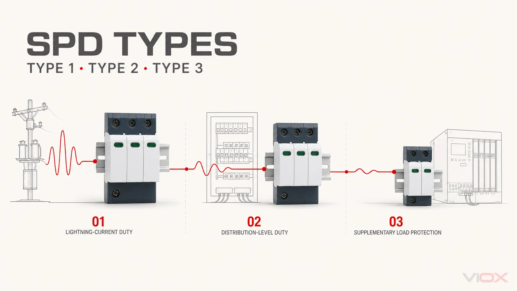
Type 1, Type 2, and Type 3 surge protective devices (SPDs) serve different test duties and protection stages. They are not better-to-worse quality grades.
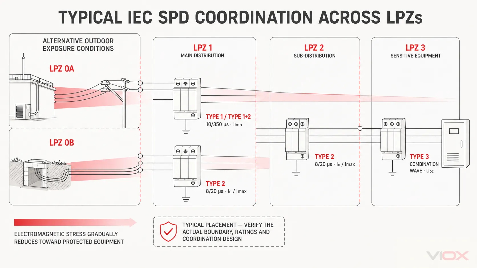
In an IEC-based low-voltage AC system, a Type 1 SPD is evaluated for lightning-current duty, a Type 2 SPD for distribution-level surge duty, and a Type 3 SPD for supplementary protection close to sensitive equipment. A project may require one type, a combined Type 1+2 or Type 2+3 device, or coordinated SPDs at more than one location.
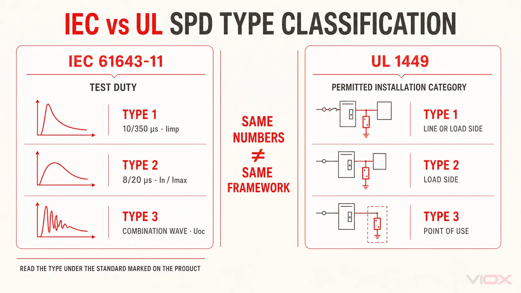
North American UL 1449 also uses Type 1, Type 2, and Type 3 labels, but its classifications place greater emphasis on where the SPD may be installed relative to the service overcurrent protective device. IEC and UL type numbers must therefore be interpreted within their own standards; they are not direct one-to-one equivalents.
Type 1 vs Type 2 vs Type 3 SPD at a Glance
The following comparison uses IEC terminology for low-voltage AC power SPDs. “Typical position” describes a protection role, not a universal installation mandate.
| Comparison point | Type 1 SPD | Type 2 SPD | Type 3 SPD |
|---|---|---|---|
| IEC test class commonly associated with the type | Class I | Class II | Class III |
| Principal test duty | Lightning impulse current | Nominal discharge current | Combination-wave response |
| Representative waveform | 10/350 μs current impulse | 8/20 μs current impulse | 1.2/50 μs open-circuit voltage and 8/20 μs short-circuit current from a combination-wave generator |
| Principal declared quantity used to recognize the duty | Iimp |
In; Imax may also be declared |
Uoc; other values depend on the device and test declaration |
| Typical protection stage | At the installation origin or lightning-protection boundary where lightning current may have to be discharged | Main or sub-distribution, where distribution-level transient overvoltages must be limited | Close to sensitive equipment as supplementary fine protection |
| What it should not be assumed to do | Provide complete downstream equipment protection by itself | Perform Type 1 lightning-current duty unless also tested and marked Type 1 | Replace the required upstream protection architecture |
| Common combined marking | Type 1+2 | Type 1+2 or Type 2+3 | Type 2+3 |
The practical distinction is:
- Type 1 is selected when lightning-current duty is part of the design requirement.
- Type 2 is the normal distribution-level SPD type when Type 1 duty is not required at that location.
- Type 3 adds protection near a sensitive load and must be coordinated with the upstream surge-protection system.
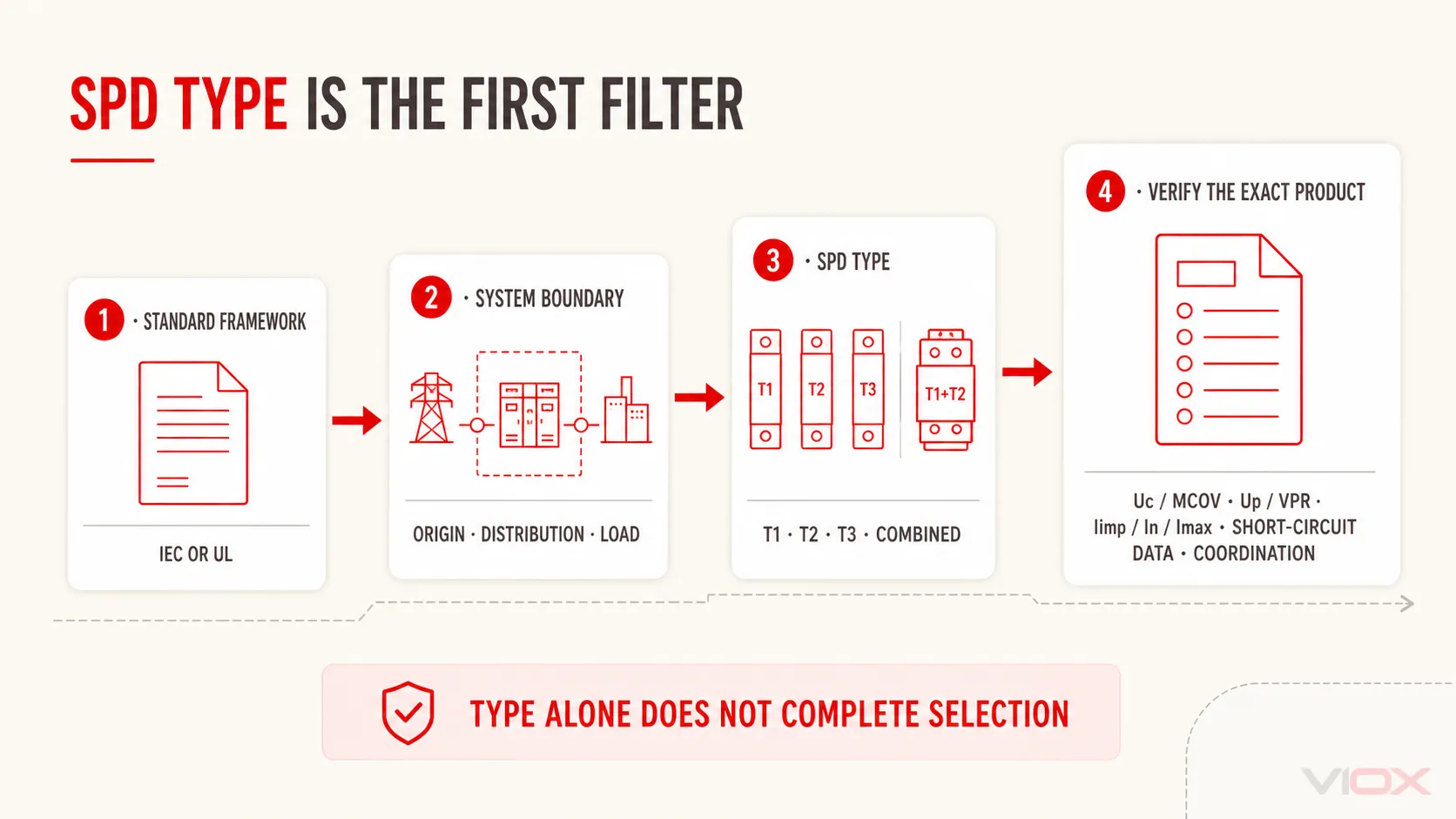
The type label is only the first filter. Final selection still requires the exact product ratings, system conditions, installation rules, and coordination evidence.
What Is a Type 1 SPD?
A Type 1 SPD is an SPD evaluated for lightning impulse current duty. In IEC practice, its defining current quantity is Iimp, tested with a 10/350 μs waveform. It is typically considered at the origin of an installation where a portion of lightning current may enter the low-voltage power system, such as at a boundary associated with an external lightning protection system.
What Type 1 classification tells you
Type 1 classification establishes the applicable impulse test duty, but it does not set a universal Iimp value or prove compatibility with a system, downstream load, national rule, or coordinated SPD arrangement. Two Type 1 SPDs can therefore have different Iimp, Uc, Up, protection modes, follow-current behavior, short-circuit capability, and backup-protection requirements.
When should Type 1 be evaluated?
Evaluate Type 1 or a combined Type 1+2 SPD when the protection design requires lightning-current discharge capability at the installation boundary. The decision commonly depends on the lightning protection system, supply arrangement, lightning-risk assessment, installation standard, and local rules.
Do not turn this into the claim that a Type 1 SPD makes equipment immune to a direct lightning strike. An SPD is one part of a coordinated lightning and surge protection concept that also depends on bonding, earthing, routing, separation, and downstream insulation coordination.
Can Type 1 replace Type 2?
Not as a universal rule. Under IEC practice, Type 1 and Type 2 describe different test duties. A device marked Type 1+2 has been evaluated for both associated duties and may be used where both are required, subject to its declared ratings and the installation design.
In the UL framework, a Listed Type 1 SPD may also be permitted at load-side locations where Type 2 devices are used. That UL installation suitability must not be rewritten as a general statement that every IEC Type 1 SPD automatically performs the system role of a Type 2 SPD.
What Is a Type 2 SPD?
A Type 2 SPD is a distribution-level surge protective device evaluated with the Class II test. Its principal IEC quantity is nominal discharge current (In) using an 8/20 μs current waveform; maximum discharge current (Imax) may also be declared. Type 2 SPDs are commonly installed in main and sub-distribution boards to limit transient overvoltages reaching downstream circuits.
Where lightning-current duty is not required at the selected point, Type 2 is often the first SPD type evaluated. Where Type 1 is installed upstream, Type 2 may form the next coordinated stage. Verify either arrangement against the applicable design and installation rules.
What Type 2 classification tells you
Type 2 confirms a defined distribution-level test duty—not a worldwide installation mandate or proof that any rating will fit any site. It also does not establish that Type 1 is always required upstream or that Type 2 alone will provide an acceptable voltage at sensitive equipment.
In and Imax are both associated with an 8/20 μs waveform, but they describe different test quantities. In represents nominal discharge-current duty; Imax is the declared maximum discharge current under the applicable test conditions. Neither is a service-current rating, and Imax is not a standalone selection metric. See Imax vs In in an SPD for the full distinction.
Type 1 vs Type 2 SPD
| Decision question | Type 1 | Type 2 |
|---|---|---|
| Is lightning-current duty required at this boundary? | Evaluate Type 1 or Type 1+2 | Type 2 alone does not establish Type 1 duty |
| Is the location a distribution stage without a Type 1 duty requirement? | May be suitable only if its full marking, ratings, and system role support the design | Common starting point |
| Which IEC current quantity distinguishes the test duty? | Iimp with 10/350 μs waveform |
In with 8/20 μs waveform; Imax may also be declared |
| Can the label alone complete selection? | No | No |
The correct question is not “Which type has the larger kA value?” Because Iimp and Imax use different waveforms and test duties, their numerical values are not directly interchangeable.
Is a Type 2 SPD enough without Type 1?
It can be, where the installation does not require Type 1 lightning-current duty and the selected Type 2 SPD satisfies the applicable system, risk, and installation requirements. Conversely, if the design requires Type 1 duty, a Type 2-only device does not meet that requirement merely because it has a high Imax rating.
What Is a Type 3 SPD?
A Type 3 SPD is evaluated with the Class III combination-wave test and is typically used close to sensitive equipment as supplementary protection. It limits the residual transient voltage at the final protection stage rather than replacing the surge-current handling required upstream.
The combination-wave generator is characterized by a 1.2/50 μs open-circuit voltage and an 8/20 μs short-circuit current. The associated Uoc value must be read in its test context; it is not directly comparable with the Iimp or Imax headline values used for other SPD duties.
Type 2 vs Type 3 SPD
| Decision question | Type 2 | Type 3 |
|---|---|---|
| Primary system role | Distribution-level surge limitation | Supplementary protection near the load |
| Typical location | Main or sub-distribution board | At or near the protected equipment |
| Principal IEC test | Class II, 8/20 μs discharge current | Class III, combination wave |
| Relationship to other SPDs | May be the main SPD stage or may follow Type 1 | Normally coordinated with upstream protection |
Type 3 is not simply “a smaller Type 2.” Its test duty and protection position differ, and no single Type 2-to-Type 3 cable distance is universal. Coordination depends on the tested product combination, conductor impedance, installation layout, protection levels, and manufacturer instructions.
The IET describes Type 3 as protection installed close to the load and supplementary to Type 2. Multiple SPDs still require confirmed coordination and compatibility.
IEC and UL SPD Types Are Different Classification Frameworks
A common error is placing “IEC 61643-11 / UL 1449” in one table as though both standards define the types identically. They do not.
IEC framework: test duty and protection role
IEC 61643-01:2024 contains the common requirements and test methods for SPDs. IEC 61643-11:2025 supplements those general requirements for SPDs connected to AC low-voltage power systems up to 1,000 V RMS. IEC states that Part 11 is to be read and applied together with the latest edition of Part 01.
Within IEC-oriented practice, Type 1, Type 2, and Type 3 communicate different test duties. This supports a staged protection concept, but the type alone does not prescribe every installation location or prove that the complete installation complies with local rules.
UL 1449 framework: permitted installation category
UL type classification is closely connected to installation position relative to the service equipment overcurrent protective device.
| UL 1449 category | Installation meaning in simplified form |
|---|---|
| Type 1 | Permanently connected SPD intended for installation between the service transformer secondary and the line side of the service overcurrent device, and also permitted on the load side; UL describes this category as intended for installation without an external overcurrent protective device |
| Type 2 | Permanently connected SPD intended for the load side of the service overcurrent device, including branch panels |
| Type 3 | Point-of-utilization SPD installed downstream, such as applicable cord-connected, direct plug-in, or receptacle-type protection covered by its listing and instructions; the UL/NEMA definition includes a minimum conductor-length condition unless the product has been evaluated for another applicable type |
This produces a critical engineering boundary:
An IEC type label helps identify the impulse test duty. A UL type label helps establish where a listed SPD is permitted in the North American distribution system. Always read the mark under the standard named on the product.
The UL framework also includes component-assembly categories. A Recognized Component is not automatically interchangeable with a Listed, field-installed SPD; the certification category and installation conditions must be checked for the exact product. The NEMA Surge Protection Institute’s UL type summary provides the additional Type 3 point-of-utilization boundary.
Which SPD Type Should You Evaluate?
Use this decision path to select the type for further engineering verification—not to select a final model from the type label alone.
| System condition | Type to evaluate first | Why | Required follow-up evidence |
|---|---|---|---|
| The installation boundary may have to discharge a portion of lightning current | Type 1 or Type 1+2 | The design includes lightning-current duty | Lightning protection concept, risk assessment, required Iimp, protection mode, system voltage, local rules |
| The location is a main or sub-distribution stage and Type 1 duty is not required there | Type 2 | Distribution-level transient limitation is the required role | Uc, Up, In, Imax, system configuration, short-circuit conditions, backup protection |
| A Type 1 stage already exists and downstream voltage must be limited further | Coordinated Type 2 or a verified combined solution | A second protection stage may improve insulation coordination | Coordination data, conductor routing, protection levels, product compatibility |
| Sensitive equipment needs additional protection near its terminals | Coordinated Type 3 or Type 2+3 | Final-stage supplementary protection is required | Equipment impulse withstand, Uoc declaration, installed lead path, upstream coordination |
| Panel space favors one device performing two test duties | Type 1+2 or Type 2+3 | A combined SPD can carry more than one tested type marking | Evidence that the exact model is marked and rated for both duties; all other system ratings remain applicable |
| The project is governed by UL 1449 rather than IEC installation practice | UL type permitted for that location | UL type numbers define a different installation framework | Listing/category, line-side or load-side position, SCCR, OCPD conditions, NEC and manufacturer instructions |
If the type is still unclear, start with the physical boundary: Where can surge current enter, what surge duty must be handled there, and what voltage must the downstream equipment withstand? Then apply the standard used by the project.
For the detailed physical placement and conductor-path considerations, use Where Should You Install SPDs in Your Electrical Panel?. This comparison page identifies the type to evaluate; the installation guide addresses how placement affects real protection.
What Do Type 1+2 and Type 2+3 Mean?
A combined marking means that the exact SPD has been evaluated for more than one applicable type duty. It does not merely mean that two cartridges share an enclosure.
Type 1+2 SPD
A Type 1+2 SPD is tested and marked for both Type 1 and Type 2 duties. It can be useful at a boundary where the design requires lightning-current discharge capability and distribution-level voltage limitation in one coordinated product.
Whether it eliminates another downstream SPD depends on its declared protection level, the conductor path, equipment impulse withstand, coordination requirements, and the manufacturer’s tested application guidance.
Type 2+3 SPD
A Type 2+3 SPD is evaluated for both Type 2 and Type 3 duties. It may be useful near a final distribution stage or sensitive load, but its marking does not remove the need to verify upstream lightning-current protection where Type 1 duty applies.
Combined SPD vs coordinated separate SPDs
Neither arrangement is universally better.
| Design option | Main advantage | Main verification point |
|---|---|---|
| Combined SPD | Compact device with more than one tested type duty | Confirm every relevant rating and protection mode on the exact model |
| Separate coordinated SPDs | Protection can be distributed across system boundaries | Confirm energy coordination, conductor effects, compatibility, and protection levels |
When devices from different manufacturers are combined, obtain explicit coordination or compatibility evidence. Do not assume that matching type numbers alone prove a coordinated system.
The Type Label Is Only the First Selection Filter
After identifying Type 1, Type 2, Type 3, or a combined type, verify the following on the exact SPD datasheet:
- Applicable product standard and type marking — confirm whether the label is IEC, UL, or another regional framework.
- AC, DC, or PV scope — do not transfer an AC SPD selection directly to a DC or photovoltaic circuit.
- System voltage and configuration — verify nominal voltage, maximum continuous operating voltage (
Ucor MCOV), frequency, and TN, TT, IT, delta, or wye compatibility as applicable. - Protection modes — confirm the protected conductor combinations, such as L–N, L–PE, N–PE, or line-to-line modes.
- Voltage protection — compare
Upor the applicable UL voltage-protection declaration with the equipment impulse withstand and the installed conductor path. - Surge-current duty — check
Iimp,In,Imax, orUoconly in the waveform and type context in which it is declared. - Short-circuit withstand/current and backup protection — for UL products, verify the short-circuit current rating (
SCCR). For IEC products, verify the applicable short-circuit withstand or current declaration, such asI_SCCR/Isccrwhere declared, together with follow-current behavior, required fuse or breaker, and disconnection provisions. - Coordination and installation instructions — check upstream/downstream compatibility, conductor length and routing, terminal requirements, status indication, and replacement method.
The detailed label-reading process is covered in How to Read an SPD Datasheet. For the two voltage parameters most often confused, see Uc vs Up in an SPD.
If you are still building the basic device model, begin with What Is a Surge Protective Device? rather than expanding this type comparison into a second general SPD guide.
For product evaluation after the engineering type has been identified, review the VIOX SPD range and request the exact model datasheet, test standard, type marking, wiring configuration, and coordination requirements. A product-family page is not evidence that every model fits every system.
Standards and Technical Sources
- IEC 61643-01:2024 — Low-voltage surge protective devices, general requirements and test methods
- IEC 61643-11:2025 — Surge protective devices connected to AC low-voltage power systems
- UL Solutions — Panelboard Application Guide, SPD Type 1 and Type 2 installation definitions
- UL Solutions — Verifying Surge Protection Devices
- IET — Surge Protective Devices
- Phoenix Contact — SPD types in accordance with UL 1449
- Phoenix Contact — Surge protection for power supplies
- Schneider Electric — How to select an SPD for an installation
- NEMA Surge Protection Institute — What Are SPDs?