このページについて
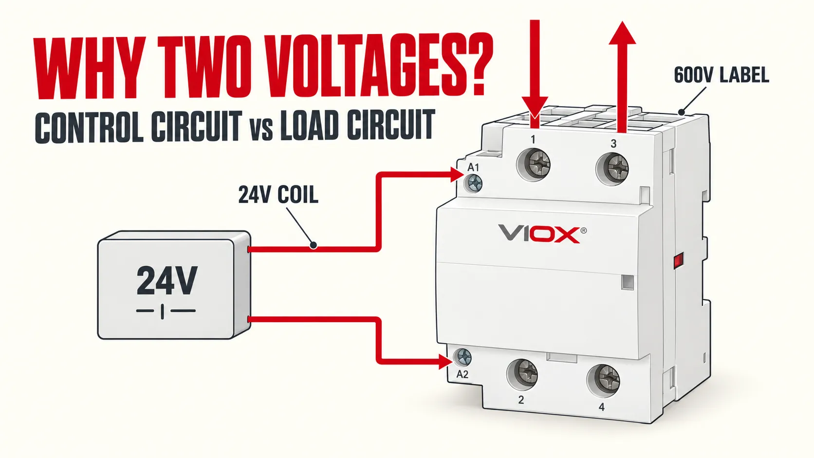
A contactor can show 24 V and 600 V because it contains two separate electrical circuits. The low-voltage control circuit energizes a coil, while the main circuit opens or closes the load through power contacts.
On most contactors, a 24 V marking beside the coil information describes the rated control-circuit voltage, Uc, applied across terminals A1 and A2. A 600 V marking may describe the rated operational voltage, Ue, or the rated insulation voltage, Ui. Those two ratings are not interchangeable, so read the symbol and the exact model datasheet before treating 600 V as an allowable switching voltage.
The contactor does not convert 24 V into 600 V and does not supply voltage to the load. It uses electromagnetic motion to operate contacts in another circuit.

A contactor has a control circuit and a main circuit
について basic function of a contactor becomes easier to understand when you treat it as two coordinated sections:
- 制御回路: A command device supplies the coil at A1 and A2. When the applied voltage is suitable for the coil, the magnetic system moves the armature.
- Main circuit: The armature changes the state of the main contacts. Those contacts switch the external load circuit through terminals such as L1/L2 and T1/T2.
The magnetic mechanism links the sections mechanically. Their electrical ratings can therefore be different. A 24 VDC PLC output can command a contactor whose main contacts switch a 230 VAC heater or a 400 VAC motor circuit, provided the exact contactor is rated for that load, voltage, current, and duty.
This separation also means that a coil marked 24 VDC does ない prove that the main contacts are suitable for a DC load. Coil supply type and contact switching capability are separate checks.
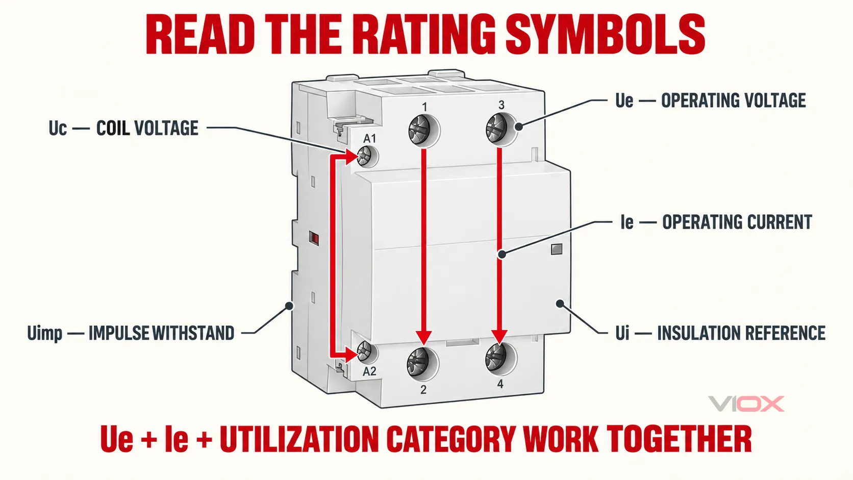
What Uc, Ue, Ie, Ui, and Uimp mean
Nameplates and datasheets use symbols because a single voltage number cannot describe every part of a contactor.
| 表示 | 意味 | 何を示しているか | 記載されていない情報 |
|---|---|---|---|
| ユーシー | Rated control-circuit voltage | The nominal supply intended for the coil/control circuit, normally across A1 and A2 | The voltage that the main contacts may switch |
| 上 | 定格動作電圧 | The main-circuit voltage associated with stated operating conditions | A complete load rating without Ie and utilization category |
| Ie | 定格動作電流 | The current the device can carry or switch under stated conditions | A universal current for every voltage and load type |
| ウイ | 定格絶縁電圧 | A reference rating for insulation coordination and dielectric design | Permission to switch a load at that voltage |
| ウインプ | 定格インパルス耐電圧 | The specified impulse level the insulation system is designed to withstand | A continuous operating or switching voltage |
The most important distinction is Ue versus Ui. If a nameplate shows “Ui 600 V,” that does not automatically mean every main-contact combination may switch 600 V in every application. Find the operational table that pairs Ue, Ie, utilization category, and pole arrangement for the exact model.
以下では IEC 60947-4-1, industrial contactor performance is considered with defined ratings and utilization conditions. Contactors for household and similar applications may instead fall within the scope of IEC 61095. The applicable standard and manufacturer data determine how the markings should be used.
How to read a 24 V / 600 V contactor nameplate
Use this sequence rather than comparing the two largest numbers on the device.
1. Find the coil marking
探す ユーシー, a coil symbol, or a voltage printed near A1 and A2. Confirm all three parts of the coil specification:
- nominal voltage, such as 24 V;
- ACまたはDC電源;
- frequency when the coil is rated for AC operation.
A 24 VAC coil and a 24 VDC coil are not automatically interchangeable. Coil construction, inrush behavior, suppression components, and allowable voltage range may differ.
2. Identify what the higher voltage number represents
Do not assume that the largest printed voltage is Ue. Check whether the number is labeled 上, ウイ, or appears only in a certification or insulation block. If the front label is abbreviated, use the exact part number to find the manufacturer’s technical data.
3. Match the operational current and utilization category
The same contacts can receive different Ie ratings for a resistive heater, a motor, or another load with high making or breaking stress. Review the relevant contactor utilization category together with Ue and Ie.
4. Confirm the poles and terminal function
Check the number of poles and whether each contact is normally open or normally closed. Use the diagram printed on the device or datasheet. If terminal labels are unfamiliar, see the guide to L1, L2, T1, and T2 on a contactor.
5. Check the installation conditions
Ambient temperature, enclosure temperature, switching frequency, coordination with protective devices, conductor size, and local rules can change the valid selection. The final authority is the technical documentation for the exact catalog number.
Three examples of separate coil and load ratings
24 VAC control with a 230/240 VAC load
In an HVAC control system, a transformer may supply 24 VAC to a thermostat and contactor coil. When the thermostat commands operation, the coil closes contacts in a separate 230/240 VAC circuit. The contactor does not raise the voltage; it only changes the state of the load contacts.
24 VDC PLC output with a 400 VAC motor circuit
A PLC can energize a 24 VDC coil while the main contacts switch a three-phase motor circuit. Selection still depends on the motor duty, operational current, utilization category, short-circuit coordination, and the exact 400 VAC rating. A matching coil voltage alone is insufficient.
Control and load at the same nominal voltage
The two circuits do not have to use different voltages. A contactor can have a 230 VAC coil and switch a 230 VAC load if its ratings and control design permit it. “Control versus load” describes circuit function, not a mandatory voltage difference.
Why might you measure 24 V on both sides of a contactor?
This question often comes from treating voltage as a property of one terminal. Voltage is a difference between two measurement points. A reading taken from each coil terminal to ground is not the same test as a reading directly across A1 and A2.
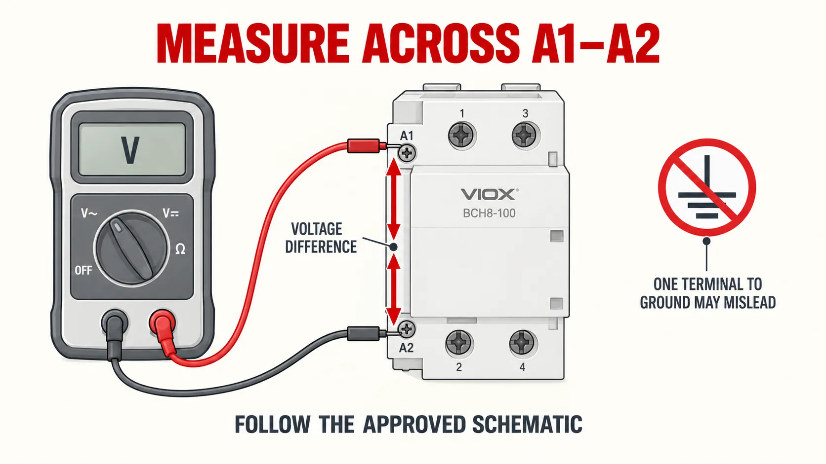
In a floating or isolated control circuit, both coil terminals may show a similar voltage relative to ground while the voltage ソース(配電ボックス)と負荷(機械またはライト)の A1 and A2 is different. High-impedance meters can also display coupled or “ghost” voltage on an open conductor. On the main contacts, identical readings can occur when the contacts are closed or when voltage is being referenced through another part of the connected circuit.
The meaningful test point depends on the schematic and the symptom. For a coil command, the relevant quantity is normally the voltage across A1 and A2 under the intended operating condition, compared with the coil datasheet. For a main contact, use the approved circuit diagram and defined line/load reference points.
Do not move probes or open an energized enclosure unless you are qualified and the site’s electrical safety procedure authorizes the work. If the measurement does not match the schematic, isolate the circuit and have a qualified person check the control source, interlocks, neutral or return path, suppression module, and connections.
Why matching voltage is only the first selection step
A contactor with the correct Uc can still be wrong for the load. Verify these items together:
- Coil supply: Uc, AC or DC, and frequency where applicable.
- Main-circuit voltage: Ue for the actual supply system.
- Operational current: Ie at that Ue and utilization category.
- Load behavior: resistive, inductive, motor starting, lighting, or another defined duty.
- Pole arrangement: number of poles and NO/NC configuration.
- Switching rate: expected operations and duty cycle.
- 調整: upstream protection and short-circuit coordination stated by the manufacturer.
- 環境: enclosure temperature, altitude, pollution degree, and installation limits.
について VIOX modular contactor selection guide explains how coil choice, operational ratings, and application category fit together.
Common interpretation mistakes
“600 V means it can switch any 600 V load”
Only if 600 V is an applicable Ue and the model also has a suitable Ie, utilization category, pole arrangement, and AC/DC switching rating. A 600 V Ui marking alone is not enough.
“A 24 VDC coil means the contacts are for DC”
Uc describes the control circuit. DC load switching must be explicitly supported in the main-contact data.
“A contactor transforms the voltage”
It does not. The control source supplies the coil; the load source supplies the load. The contactor provides controlled switching and electrical separation between those circuit functions.
“The same amp rating applies to every load”
Ie is tied to stated conditions. A resistive-load rating cannot be transferred automatically to motor starting or DC interruption.
“A1 and A2 readings to ground prove the coil is energized”
The coil responds to the voltage across its two terminals. Individual readings to ground can be misleading, especially in isolated control circuits.
選定チェックリスト
Before choosing or replacing a contactor, record:
- the full catalog number;
- Uc, supply type, and AC frequency if applicable;
- Ue and Ie for the intended utilization category;
- pole and NO/NC arrangement;
- load type and switching frequency;
- applicable environmental and coordination requirements.
Then compare those values with the exact manufacturer datasheet. For DIN-rail applications, review the available VIOXモジュラーコンタクタシリーズ and select the coil option and main-circuit rating as separate requirements.