
Selecting between electronic and thermal-magnetic molded case circuit breakers isn’t about choosing “better” technology—it’s about matching protection capabilities to your specific application requirements. While thermal-magnetic MCCBs remain the workhorse of industrial protection due to their proven reliability and cost-effectiveness, electronic trip units deliver precision, flexibility, and intelligence that certain applications absolutely require. Understanding when that threshold is crossed determines whether you’re investing wisely or overpaying for unnecessary features.
Electronic MCCBs become essential when your application demands trip accuracy within ±5%, requires selective coordination across multiple protection levels, needs real-time power monitoring and predictive maintenance capabilities, or operates in environments where ambient temperature significantly affects thermal-magnetic performance. For standard industrial applications with straightforward protection requirements, thermal-magnetic MCCBs deliver reliable performance at 40-60% lower cost.
The global MCCB market reached $9.48 billion in 2025, with electronic trip units growing at 15% annually as industries embrace smart protection technologies. By the end of 2026, 95% of new industrial IoT deployments will feature AI-powered analytics integrated with electronic MCCBs, transforming circuit breakers from passive protection devices into active system intelligence sources. This shift isn’t driven by marketing—it’s driven by measurable improvements in system reliability, energy efficiency, and operational visibility that electronic technology enables.
Key Takeaways
- Electronic MCCBs offer ±5% trip accuracy versus ±20% for thermal-magnetic, critical for precise coordination and avoiding nuisance trips
- Programmable L-S-I-G protection curves enable selective coordination impossible with fixed thermal-magnetic characteristics
- Real-time monitoring capabilities (current, voltage, power, energy, harmonics) justify the 100-150% cost premium for critical facilities
- Ambient temperature independence—electronic units maintain accuracy from -25°C to +70°C without derating
- Predictive maintenance features reduce unplanned downtime by 30-50% through contact resistance monitoring and failure prediction
- Choose thermal-magnetic for applications <400A with simple protection requirements and limited budget constraints
- Choose electronic for critical facilities (data centers, hospitals, manufacturing), coordination-intensive systems, or where monitoring provides operational value
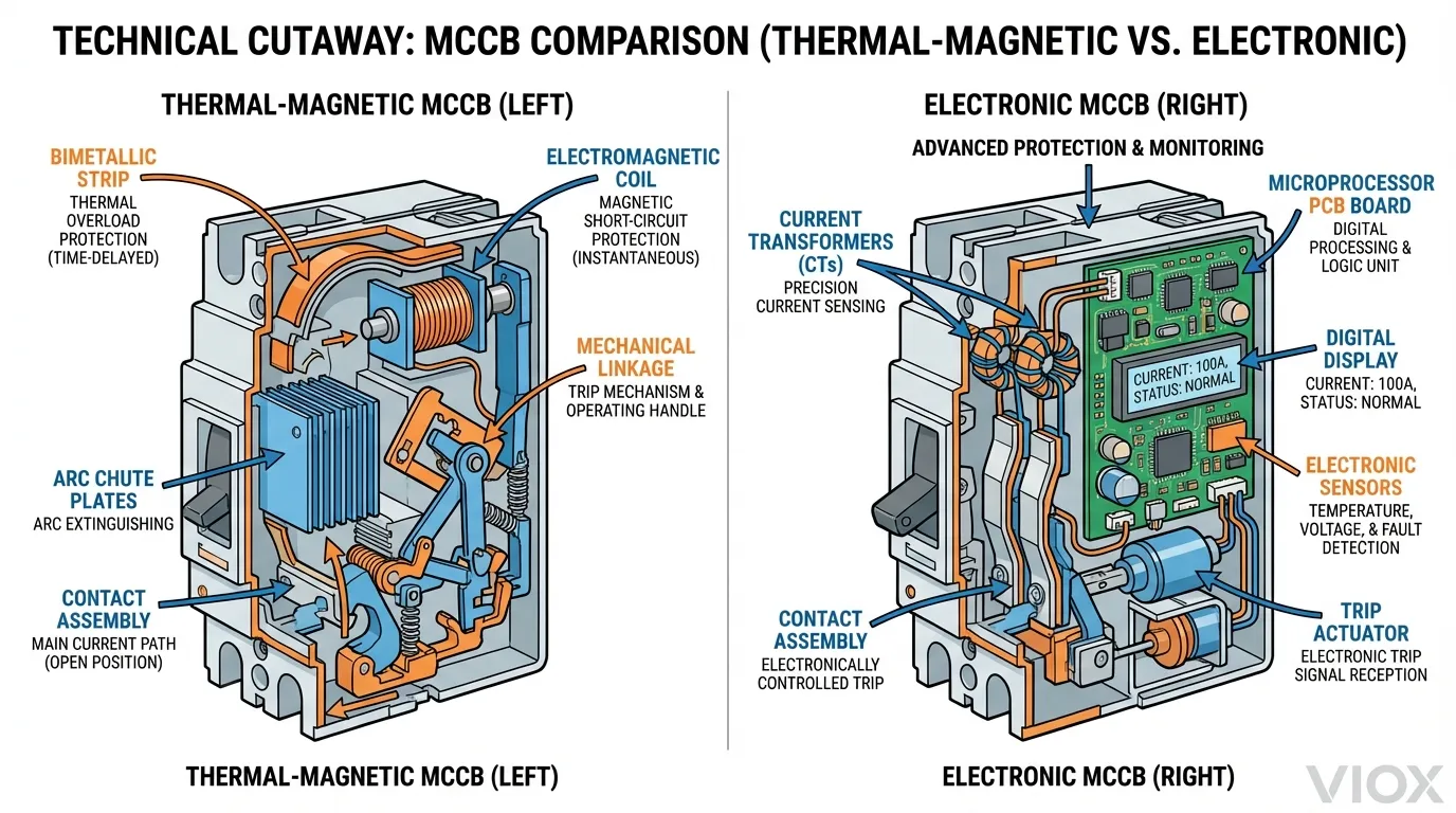
Understanding the Fundamental Difference
The distinction between thermal-magnetic and electronic MCCBs lies not in what they protect against—both handle overload, short-circuit, and ground fault conditions—but in how they sense, measure, and respond to abnormal currents.
Thermal-magnetic MCCBs employ purely electromechanical components that have remained fundamentally unchanged for decades. A bimetallic strip heats and bends under sustained overcurrent (thermal protection), while an electromagnetic coil generates magnetic force proportional to current magnitude for instantaneous short-circuit protection (magnetic protection). These mechanisms are inherently analog, temperature-dependent, and offer limited or no adjustability.
Electronic MCCBs replace these mechanical elements with current transformers (CTs) that measure current in each phase, feeding digital signals to a microprocessor-based trip unit. The microprocessor continuously analyzes current waveforms, calculates RMS values, tracks thermal accumulation digitally, and executes programmable protection algorithms. This digital approach fundamentally changes what’s possible in circuit protection.
The implications extend far beyond the trip mechanism itself. Electronic trip units enable features impossible with thermal-magnetic technology: sub-second data logging, communication protocols for building management systems, ground fault protection with adjustable sensitivity, and—most significantly—protection characteristics that remain stable regardless of ambient temperature or previous operating history.
Accuracy: The 5% vs. 20% Reality
Trip accuracy represents the deviation between the breaker’s set point and its actual trip current. This seemingly technical specification has profound practical implications for system design, equipment protection, and operational reliability.
Thermal-magnetic MCCBs typically achieve ±10-20% accuracy on overload protection due to inherent variability in bimetallic strip characteristics, manufacturing tolerances, and temperature sensitivity. A breaker set to trip at 100A might actually trip anywhere from 80A to 120A depending on ambient temperature, how recently it operated, and individual unit variation. Instantaneous magnetic trip accuracy is somewhat better (±15%) but still significant.
Electronic MCCBs deliver ±5% accuracy or better across their entire operating range because microprocessors don’t drift, don’t wear mechanically, and aren’t affected by ambient temperature (the CTs and electronics operate independently of environmental conditions). A 100A electronic trip setting means 95A to 105A actual trip current—consistently and repeatably.
Why This Matters in Real Applications
Motor Protection: A 100 HP motor with 124A full-load current requires protection at 156A per NEC 430.52 (125% for inverse-time breakers). With a thermal-magnetic MCCB, the ±20% tolerance means actual trip could occur anywhere from 125A to 187A. At 125A, you’ll experience nuisance trips during normal operation. At 187A, you’ve compromised motor protection. An electronic MCCB maintains 148A to 164A—tight enough to protect without nuisance tripping.
Coordination: Achieving selective coordination requires maintaining sufficient time-current separation between upstream and downstream devices. The ±20% uncertainty of thermal-magnetic breakers forces you to oversize upstream devices significantly to ensure coordination under worst-case conditions. Electronic accuracy allows tighter coordination margins, often enabling one frame size smaller on upstream protection—savings that can offset the electronic premium.
Comparison Table: Trip Accuracy Impact
| Parameter | Thermal-Magnetic MCCB | Electronic MCCB | Practical Impact |
|---|---|---|---|
| Long-Time Trip Accuracy | ±10-20% | ±5% | Electronic prevents nuisance trips while maintaining protection |
| Short-Time Trip Accuracy | ±15-25% | ±5% | Electronic enables tighter coordination margins |
| Instantaneous Trip Accuracy | ±15% | ±5% | Electronic allows precise setting above inrush without compromising protection |
| Temperature Coefficient | 0.5-1.0% per °C | <0.1% per °C | Electronic maintains accuracy in hot environments (near furnaces, outdoor enclosures) |
| Repeatability | ±10% trip-to-trip | ±2% trip-to-trip | Electronic provides consistent protection over equipment lifetime |
Adjustability and Programmability: Fixed vs. Flexible Protection
The protection requirements for a 400A distribution panel feeding mixed loads differ dramatically from a 400A motor feeder. Thermal-magnetic MCCBs address this through limited mechanical adjustment (typically 80-100% of rating on larger frames) or by stocking multiple breaker ratings. Electronic MCCBs solve it through comprehensive programmability.
Thermal-Magnetic Adjustment Limitations
Most thermal-magnetic MCCBs below 250A offer zero adjustability—the trip curve is fixed at the factory. Larger frames (400A+) may provide:
- Thermal adjustment: Rotary dial setting overload trip from 0.8× to 1.0× breaker rating
- Magnetic adjustment: Limited adjustment of instantaneous trip (typically 5× to 10× rating)
- No time delay adjustment: The inverse-time characteristic is fixed by the bimetallic strip design
This limited flexibility means you often must oversize breakers to accommodate load variations or accept less-than-optimal protection for your actual operating conditions.
Electronic Trip Unit Capabilities
Electronic MCCBs provide full programmable control over all protection functions:
Long-Time (L) Protection:
- Adjustable pickup: 0.4× to 1.0× breaker rating (some models 0.2× to 1.0×)
- Adjustable time delay: Selectable I²t curves or fixed time delays
- Thermal memory: Accounts for load history to prevent thermal accumulation
Short-Time (S) Protection:
- Adjustable pickup: 1.5× to 10× breaker rating
- Adjustable time delay: 0.05s to 0.5s (critical for coordination)
- I²t or definite time characteristics
Instantaneous (I) Protection:
- Adjustable pickup: 2× to 40× breaker rating (application-dependent)
- Can be disabled entirely for applications requiring only L-S protection
Ground Fault (G) Protection:
- Adjustable sensitivity: 20% to 100% of breaker rating
- Adjustable time delay: 0.1s to 1.0s
- Selectable I²t or definite time
This programmability enables a single electronic MCCB frame size to serve applications that would require 4-6 different thermal-magnetic breaker ratings, reducing inventory costs and improving standardization.
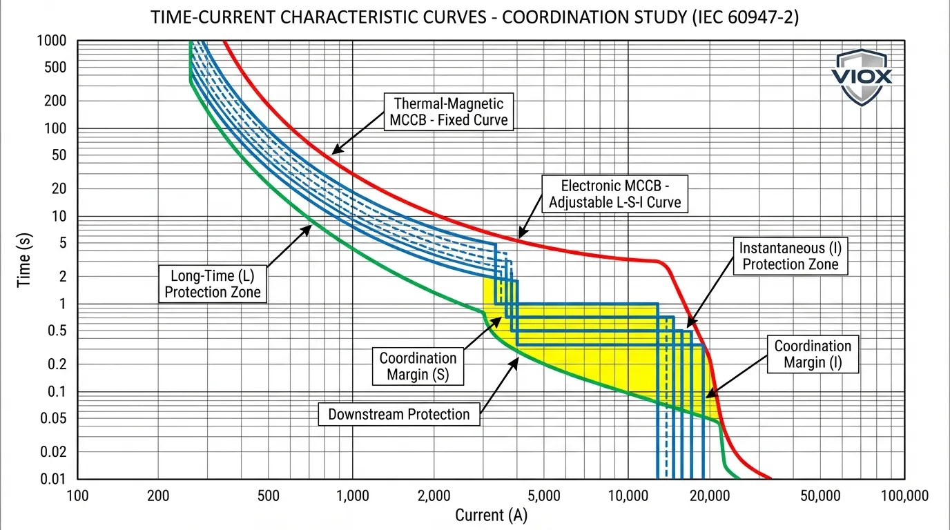
Selective Coordination: Where Electronic MCCBs Excel
Selective coordination—ensuring only the breaker immediately upstream of a fault operates—is straightforward in theory but challenging in practice. The goal is preventing widespread outages when faults occur on branch circuits, maintaining power to unaffected loads.
The Thermal-Magnetic Coordination Challenge
Achieving coordination with thermal-magnetic MCCBs requires significant current ratio between upstream and downstream devices (typically 2:1 minimum, often 3:1 for reliable coordination). This forces oversizing of upstream breakers, increasing costs and potentially compromising protection. Even with proper sizing, coordination may only be achievable up to a certain fault current level—beyond that, both breakers trip.
The fixed time-current curves of thermal-magnetic breakers provide limited flexibility. You can’t adjust the thermal response time or add intentional delay to create coordination separation. Your only tools are device selection and current ratio.
Electronic MCCB Coordination Advantages
Electronic trip units solve coordination through programmable short-time delay. The upstream breaker can be set to delay tripping for 0.1-0.3 seconds, giving the downstream device time to clear the fault first. This “intentional delay” approach enables coordination with much smaller current ratios (1.5:1 often sufficient) and maintains coordination across the full fault current range.
Zone Selective Interlocking (ZSI) takes this further—electronic MCCBs communicate via hardwired signals or network protocols. When a fault occurs, the downstream breaker detecting the fault sends a “restrain” signal to upstream breakers, telling them “I see this fault, delay your trip.” If the downstream breaker successfully clears the fault, upstream breakers never trip. If the downstream breaker fails, the upstream breaker trips after its delay expires.
Coordination Comparison Table
| Coordination Aspect | Thermal-Magnetic MCCB | Electronic MCCB | Advantage |
|---|---|---|---|
| Minimum Current Ratio | 2:1 to 3:1 required | 1.5:1 sufficient | Electronic reduces oversizing requirements |
| Coordination Range | Limited to specific fault current range | Full range coordination possible | Electronic maintains selectivity at all fault levels |
| Time Separation | Fixed by device characteristics | Programmable 0.05-0.5s delays | Electronic enables precise coordination |
| Zone Selective Interlocking | Not available | Standard feature on most models | Electronic provides communication-based coordination |
| Coordination Study Complexity | Multiple iterations, limited solutions | Flexible programming, multiple solutions | Electronic simplifies engineering |
| Future Modifications | May require device replacement | Reprogram existing breakers | Electronic adapts to system changes |
For facilities where coordination is mandated by code (healthcare facilities per NEC 700.28, emergency systems, life safety systems), electronic MCCBs often become the only practical solution.
Monitoring and Communication: Intelligence vs. Protection-Only
Traditional thermal-magnetic MCCBs are binary devices—they’re either closed (conducting) or open (interrupted). They provide no information about load current, power consumption, power quality, or their own health status. Electronic MCCBs transform circuit breakers into intelligent system components.
Real-Time Monitoring Capabilities
Electronic trip units continuously measure and display:
- Current per phase: Real-time amperage on each conductor
- Voltage: Line-to-line and line-to-neutral measurements
- Power: Active power (kW), reactive power (kVAR), apparent power (kVA)
- Power Factor: Leading or lagging, with correction recommendations
- Energy: Cumulative kWh consumption for cost allocation
- Harmonics: THD (Total Harmonic Distortion) measurement and analysis
- Demand: Peak demand tracking for utility billing optimization
This data isn’t just displayed locally—it’s available via communication protocols (Modbus RTU/TCP, BACnet, Ethernet/IP, Profibus) for integration with building management systems, SCADA systems, and energy management platforms.
Predictive Maintenance and Diagnostics
Electronic MCCBs track parameters that indicate developing problems before failure occurs:
Contact Wear Monitoring: Measures contact resistance over time. Gradual increase indicates contact erosion—the breaker can be scheduled for replacement during planned maintenance rather than failing unexpectedly.
Thermal Accumulation: Tracks thermal load history to predict remaining life under current operating conditions. Warns if sustained overload is reducing breaker lifespan.
Operation Counting: Records number of switching operations (mechanical endurance) and fault interruptions (electrical endurance). Alerts when approaching rated endurance limits.
Trip History: Logs every trip event with timestamp, current magnitude, and trip reason. Essential for troubleshooting recurring problems and identifying load issues.
Alarm and Warning Thresholds: Programmable alerts for approaching overload, power quality issues, ground fault detection, or maintenance requirements. Can trigger local alarms or remote notifications.
The ROI of Monitoring
For critical facilities operating 24/7, the monitoring capabilities alone often justify electronic MCCB costs:
Energy Management: Identifying inefficient equipment, optimizing power factor, participating in demand response programs. Typical savings: 5-15% of electrical costs.
Downtime Prevention: Predictive maintenance reduces unplanned outages by 30-50%. For a data center where downtime costs $5,000-$10,000 per minute, preventing a single 4-hour outage pays for the electronic MCCB premium 10× over.
Compliance and Reporting: Automated energy reporting for ISO 50001, LEED certification, utility incentive programs, and corporate sustainability initiatives.
Temperature Independence: A Critical Advantage
Thermal-magnetic MCCBs are, by definition, temperature-sensitive devices—the bimetallic strip’s deflection depends on temperature. This creates two significant challenges:
Ambient Temperature Derating: Standard thermal-magnetic MCCBs are rated at 40°C ambient. For every 5°C above this, you must derate the breaker by approximately 5%. An MCCB in a 60°C environment (common near furnaces, in direct sunlight, or poorly ventilated enclosures) operates at only 80% of its nameplate rating. A 100A breaker effectively becomes an 80A breaker.
Load History Effects: After carrying high current, the bimetallic strip remains hot, making the breaker more sensitive to subsequent overloads. This “thermal memory” effect is unpredictable and can cause nuisance tripping in applications with varying loads.
Electronic MCCBs eliminate both issues. Current transformers and electronic circuits operate independently of ambient temperature. A 100A electronic trip setting remains 100A whether the breaker is installed in an Arctic outdoor enclosure at -25°C or next to a furnace at +70°C. The microprocessor can even implement sophisticated thermal models that account for conductor heating and load history more accurately than physical bimetallic strips ever could.
Temperature Performance Comparison
| Operating Condition | Thermal-Magnetic MCCB | Electronic MCCB | Impact |
|---|---|---|---|
| 40°C Ambient (Standard) | 100% rated capacity | 100% rated capacity | Both perform as rated |
| 60°C Ambient (Hot Environment) | ~80% rated capacity (requires derating) | 100% rated capacity (no derating) | Electronic maintains full capacity |
| -25°C Ambient (Cold Environment) | May not trip at rated current (bimetal stiff) | 100% rated capacity | Electronic provides reliable protection |
| After High Load Operation | Temporarily more sensitive (hot bimetal) | Consistent performance | Electronic eliminates nuisance trips |
| Rapid Load Cycling | Unpredictable due to thermal lag | Consistent response | Electronic provides stable protection |
For applications in extreme environments—outdoor installations, near heat sources, or in temperature-controlled spaces—electronic MCCBs often become necessary simply to maintain reliable protection.
Cost Analysis: When the Premium is Justified
Electronic MCCBs cost 100-150% more than equivalent thermal-magnetic units. A 400A thermal-magnetic MCCB might cost $400-$600, while the electronic version runs $900-$1,500. This premium demands justification.
Initial Cost Comparison (400A MCCB Example)
| MCCB Type | Initial Cost | Adjustability | Monitoring | Coordination | Temperature Independence |
|---|---|---|---|---|---|
| Fixed Thermal-Magnetic | $400 | None | None | Limited | No (requires derating) |
| Adjustable Thermal-Magnetic | $550 | Limited (0.8-1.0× rating) | None | Moderate | No (requires derating) |
| Electronic (Standard) | $1,000 | Full L-S-I-G programming | Basic (local display) | Excellent | Yes |
| Electronic (Smart/IoT) | $1,500 | Full L-S-I-G programming | Comprehensive + communication | Excellent + ZSI | Yes |
Total Cost of Ownership (20-Year Lifespan)
Initial cost represents only 15-25% of total ownership cost. Consider:
Thermal-Magnetic MCCB (400A):
- Initial cost: $550
- Energy costs (no monitoring): $0 savings
- Downtime costs (reactive maintenance): $25,000 over 20 years (estimated 3 unplanned outages)
- Coordination limitations: $5,000 (oversized upstream protection)
- Total 20-year cost: $30,550
Electronic MCCB (400A):
- Initial cost: $1,200
- Energy savings (5% reduction through monitoring): $15,000 over 20 years
- Downtime costs (predictive maintenance): $7,500 over 20 years (estimated 1 unplanned outage)
- Coordination optimization: $0 (proper sizing enabled)
- Total 20-year cost: $-6,300 (net savings)
Break-even point: Typically 18-36 months for critical applications, 3-5 years for standard industrial applications.
When Thermal-Magnetic Makes Sense
Electronic MCCBs aren’t always the right choice. Thermal-magnetic remains appropriate when:
- Current rating <400A with straightforward protection requirements
- Non-critical applications where monitoring provides no operational value
- Simple systems without coordination complexity
- Budget constraints where initial cost is the primary driver
- Maintenance capabilities don’t support electronic device management
Application Decision Matrix
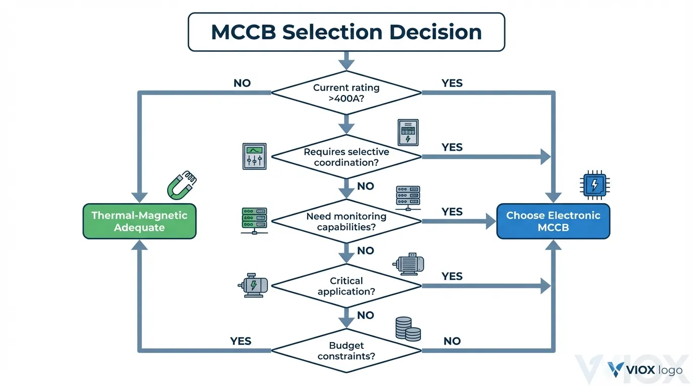
Choose Electronic MCCB When:
- ✓ Current rating ≥400A (electronic premium is smaller percentage of total cost)
- ✓ Critical facility operations (data centers, hospitals, 24/7 manufacturing, emergency systems)
- ✓ Selective coordination required by code (NEC 700.28) or operational necessity
- ✓ Monitoring capabilities provide value (energy management, demand response, predictive maintenance)
- ✓ Extreme ambient temperatures (-25°C to +70°C) where thermal-magnetic requires significant derating
- ✓ Complex systems with multiple protection levels requiring precise coordination
- ✓ Applications with varying loads where programmability prevents nuisance tripping
- ✓ Integration with BMS/SCADA for facility management and automation
Choose Thermal-Magnetic MCCB When:
- ✓ Current rating <400A with simple protection requirements
- ✓ Non-critical applications where downtime costs are minimal
- ✓ Straightforward protection without coordination complexity
- ✓ Budget-constrained projects where initial cost is primary concern
- ✓ Standard ambient conditions (0-40°C) without derating requirements
- ✓ No monitoring requirements or existing energy management systems
- ✓ Maintenance staff lack training/tools for electronic device management
Comparison Table: Electronic vs. Thermal-Magnetic MCCBs
| Feature | Thermal-Magnetic MCCB | Electronic MCCB | Winner |
|---|---|---|---|
| Trip Accuracy | ±10-20% | ±5% | Electronic |
| Temperature Independence | No (requires derating) | Yes (full range -25°C to +70°C) | Electronic |
| Adjustability | Limited or none | Full L-S-I-G programming | Electronic |
| Selective Coordination | Requires 2-3:1 current ratio | Achievable with 1.5:1 ratio + ZSI | Electronic |
| Monitoring Capabilities | None | Comprehensive (I, V, P, PF, kWh, THD) | Electronic |
| Predictive Maintenance | Not available | Contact resistance, thermal tracking, operation counting | Electronic |
| Communication Protocols | None | Modbus, BACnet, Ethernet/IP, Profibus | Electronic |
| Initial Cost (400A) | $400-$600 | $900-$1,500 | Thermal-Magnetic |
| Complexity | Simple, proven technology | Requires technical knowledge | Thermal-Magnetic |
| Reliability | Excellent (mechanical simplicity) | Excellent (no moving parts in trip unit) | Tie |
| Maintenance Requirements | Minimal | Firmware updates, calibration verification | Thermal-Magnetic |
| Inventory Reduction | Requires multiple ratings | One frame serves multiple applications | Electronic |
| Total Cost of Ownership (20yr) | Higher for critical applications | Lower due to savings and prevented downtime | Electronic (critical apps) |
Real-World Application Examples
Case Study 1: Data Center Distribution
Application: 1,200A main distribution panel feeding multiple 400A server rack panels
Challenge: Achieving selective coordination while maintaining full capacity utilization, real-time monitoring for PUE (Power Usage Effectiveness) calculation, predictive maintenance to prevent unplanned outages
Solution: Electronic MCCBs with ZSI coordination and comprehensive monitoring
Results:
- Selective coordination achieved with 1.6:1 current ratio (thermal-magnetic would require 3:1)
- Real-time power monitoring enabled 8% energy reduction through load optimization
- Predictive maintenance prevented 2 potential failures over 3 years
- ROI: 14 months
Why Electronic Won: The monitoring capabilities alone justified the cost, coordination requirements made it necessary, and downtime prevention provided 10× return on premium investment.
Case Study 2: Manufacturing Motor Control Center
Application: 600A MCC feeding 15 motors ranging from 25 HP to 150 HP
Challenge: Motor starting inrush causing nuisance trips, coordination with downstream motor starters, varying load conditions across production shifts
Solution: Electronic MCCBs with programmable instantaneous trip and short-time delay
Results:
- Eliminated nuisance trips during motor starts by setting instantaneous trip at 12× rating
- Achieved coordination with all downstream starters using 0.2s short-time delay
- Adjusted long-time settings for different production schedules without device replacement
- ROI: 28 months
Why Electronic Won: The programmability prevented nuisance trips that were costing $5,000 per production stoppage, coordination enabled proper protection without oversizing, and flexibility accommodated operational changes.
Case Study 3: Commercial Building Distribution
Application: 225A lighting and receptacle panel in office building
Challenge: Standard protection requirements, budget-conscious project, no monitoring requirements
Solution: Fixed thermal-magnetic MCCB
Results:
- Reliable protection at 60% lower cost than electronic alternative
- Simple installation and commissioning
- No training required for maintenance staff
- Appropriate technology for application requirements
Why Thermal-Magnetic Won: The application didn’t require electronic capabilities, initial cost was primary concern, and simple protection was adequate for non-critical loads.
Frequently Asked Questions
Q: Do electronic MCCBs require external power to operate?
A: Most electronic trip units are self-powered, deriving operating power from the current flowing through the breaker via the current transformers. They don’t require external control power and will trip properly even during power outages. Some advanced features (communication, display backlight) may require auxiliary power, but core protection functions remain self-powered.
Q: Are electronic MCCBs more prone to failure than thermal-magnetic?
A: No. Electronic trip units have no moving parts in the sensing/measurement circuitry, eliminating mechanical wear that affects bimetallic strips. Field reliability data shows electronic MCCBs achieve equal or better reliability than thermal-magnetic units. The microprocessor and electronics are solid-state components with MTBF (Mean Time Between Failures) exceeding 100,000 hours. The mechanical operating mechanism (contacts, arc chutes) is identical between both types.
Q: Can I retrofit thermal-magnetic MCCBs with electronic trip units?
A: Some MCCB manufacturers offer interchangeable trip units, allowing field replacement of thermal-magnetic units with electronic versions in the same breaker frame. However, this is not universal—many MCCBs have integrated trip units that cannot be changed. Check with the manufacturer for your specific model. When possible, retrofitting can be cost-effective compared to complete breaker replacement.
Q: How often do electronic trip units need calibration?
A: Electronic MCCBs typically require calibration verification every 3-5 years, compared to annual testing recommended for thermal-magnetic units. The digital nature of electronic trips provides inherent stability—microprocessors don’t drift like mechanical components. When testing shows calibration drift, it’s usually due to CT aging rather than electronics failure, and often indicates approaching end-of-life requiring breaker replacement rather than calibration adjustment.
Q: Will electronic MCCBs work with my existing building management system?
A: Most modern electronic MCCBs support standard industrial communication protocols (Modbus RTU/TCP, BACnet, Ethernet/IP, Profibus). Verify protocol compatibility with your BMS before specifying. Some manufacturers offer gateway devices to translate between protocols. Basic monitoring data (current, voltage, power, status) integrates easily; advanced features may require manufacturer-specific software or drivers.
Q: Are there applications where thermal-magnetic is actually better than electronic?
A: Yes. For simple, non-critical applications under 400A where monitoring provides no value and coordination is straightforward, thermal-magnetic MCCBs offer appropriate protection at lower cost with simpler maintenance requirements. The mechanical simplicity of thermal-magnetic technology provides inherent reliability without requiring technical expertise for management. Not every application needs or benefits from electronic sophistication.
Conclusion: Making the Right Choice for Your Application
The decision between electronic and thermal-magnetic MCCBs isn’t about choosing “better” technology—it’s about matching protection capabilities to application requirements and operational priorities. Electronic MCCBs deliver measurable advantages in accuracy, programmability, coordination, monitoring, and temperature independence that certain applications absolutely require. For critical facilities, complex systems, or applications where monitoring provides operational value, the 100-150% cost premium typically pays for itself within 18-36 months through energy savings, prevented downtime, and operational improvements.
However, thermal-magnetic MCCBs remain the appropriate choice for straightforward applications where their proven reliability, lower cost, and simpler maintenance requirements align with project constraints and operational needs. The key is understanding your specific requirements—protection accuracy needed, coordination complexity, monitoring value, ambient conditions, and budget constraints—and selecting the technology that best addresses those needs.
As industrial facilities increasingly embrace IoT connectivity, predictive maintenance, and energy management, electronic MCCBs are becoming the default choice for new installations above 400A. The “smart protection revolution” isn’t just about technology advancement—it’s about measurable improvements in system reliability, operational visibility, and total cost of ownership that electronic protection enables.
At VIOX Electric, we manufacture both thermal-magnetic and electronic MCCBs designed for industrial and commercial applications. Our engineering team provides technical support for proper selection, coordination studies, and system design to ensure your electrical distribution system delivers optimal protection and reliability. Whether your application requires the proven simplicity of thermal-magnetic protection or the advanced capabilities of electronic trip units, we can help you make the right choice.
