
Introduction: Why Cable Size Matters
Selecting the correct cable size isn’t just an engineering formality—it’s a critical safety decision that affects every electrical installation. Whether you’re wiring a residential building, designing industrial machinery, or planning a solar power system, the cross-sectional area of your conductors determines how much current can flow safely, how much voltage will be lost over distance, and ultimately, whether your system will operate reliably or become a fire hazard.
Electrical professionals worldwide use different measurement systems: the metric square millimeter (mm²) common in Europe and Asia, the American Wire Gauge (AWG) standard in North America, and the British Standard (B&S) system found in legacy installations and specific applications. Confusion between these systems can lead to dangerous undersizing or costly oversizing. This guide cuts through the complexity, providing clear explanations, practical conversion tables, and a systematic approach to cable sizing that meets international standards like IEC 60228, NEC Chapter 9, and BS 7211.
By understanding cable size types, you’ll make informed decisions that balance safety, efficiency, and cost—whether you’re replacing a damaged section, expanding a circuit, or designing from scratch.
Millimeter (mm) and Square Millimeter (mm²) Systems
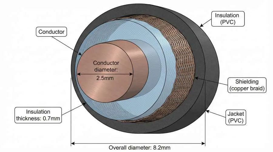
The metric system measures cable size in two related but distinct ways: millimeter (mm) for diameter and square millimeter (mm²) for cross-sectional area. While mm gives you the physical width of the conductor, mm² tells you how much copper is actually available to carry current—making it the more important specification for electrical design.
Why mm² Matters More Than Diameter
Think of water flowing through a pipe: the pipe’s diameter (mm) matters, but what really determines flow capacity is the internal area (mm²). Similarly, a cable’s current-carrying capacity depends primarily on its cross-sectional area, not just its diameter. Two cables with the same diameter could have different areas if one uses solid copper and the other uses stranded conductors with air gaps.
IEC 60228 Standard Sizes
The international standard IEC 60228:2023 defines nominal conductor areas for insulated cables. These values range from 0.5 mm² for small electronic applications to 3,500 mm² for high-voltage transmission lines. For most building and industrial wiring, you’ll encounter these common sizes:
| Nominal Area (mm²) | Typical Applications |
|---|---|
| 1.5 mm² | Lighting circuits, small appliances |
| 2.5 mm² | Socket outlets, general power circuits |
| 4 mm² | Kitchen circuits, larger appliances |
| 6 mm² | Cooker circuits, air conditioning |
| 10 mm² | Sub-main distribution, larger equipment |
| 16 mm² | Three-phase machinery, commercial distribution |
| 25 mm² | Industrial motors, main risers |
| 35 mm² & above | Power distribution, substation connections |
Key Features of the Metric System
- Linear Scale: Doubling the mm² value doubles the conductor area and roughly doubles current capacity.
- Standardized Steps: Manufacturers produce cables in predefined nominal sizes, ensuring compatibility across suppliers.
- Resistance-Based Definition: Under IEC 60228, a “2.5 mm²” cable must meet a maximum resistance per kilometer (typically 7.41 Ω/km for copper at 20°C), not just a physical dimension. This guarantees consistent electrical performance.
When You Might See “mm” Instead of “mm²”
In some contexts—particularly with automotive or battery cables—you might encounter sizes like “6mm auto cable.” This usually refers to the total outer diameter including insulation, not the conductor area. Always check the actual copper cross-section for current calculations.
American Wire Gauge (AWG) System
Across the United States, Canada, and much of North America, electrical cable size follows the American Wire Gauge (AWG) system—a logarithmic scale where larger numbers mean thinner wires. Unlike the metric system’s direct area measurement, AWG numbers originated from 19th-century wire drawing practices, creating a counterintuitive but precise standard that electricians have used for generations.
How AWG Numbers Work: The Inverse Scale
The first thing to understand about AWG is its inverse relationship: AWG 14 is thicker than AWG 20. This comes from the historical definition where “gauge” referred to how many times a wire was pulled through a reducing die. A 20-gauge wire underwent 20 draws, making it thinner than a 10-gauge wire that required only 10 draws.
Two practical rules help navigate the scale:
- Decrease by 3, double the area: Moving from AWG 14 to AWG 11 roughly doubles the cross-sectional area and current capacity.
- Decrease by 6, double the diameter: Going from AWG 12 to AWG 6 approximately doubles the physical width.
AWG Sizes and Current Ratings
Below is a reference table showing common AWG sizes with their metric equivalents and typical current ratings. Note that actual ampacity depends on insulation temperature rating, installation environment (free air vs. conduit), and local codes like the National Electrical Code (NEC).
| AWG Size | Diameter (mm) | Area (mm²) | NEC Rating (60°C Cu) | Free Air Rating (90°C Cu) |
|---|---|---|---|---|
| 14 AWG | 1.63 | 2.08 | 15 A | 32 A |
| 12 AWG | 2.05 | 3.31 | 20 A | 41 A |
| 10 AWG | 2.59 | 5.26 | 30 A | 55 A |
| 8 AWG | 3.26 | 8.37 | 40 A | 73 A |
| 6 AWG | 4.12 | 13.30 | 55 A | 101 A |
| 4 AWG | 5.19 | 21.15 | 70 A | 135 A |
| 2 AWG | 6.54 | 33.62 | 95 A | 181 A |
| 1/0 AWG | 8.25 | 53.49 | 125 A | 245 A |
| 4/0 AWG | 11.68 | 107.22 | 195 A | 380 A |
Beyond AWG: kcmil and MCM
For conductors larger than 4/0 AWG (0000), the system switches to thousand circular mils (kcmil or MCM). One circular mil is the area of a circle with a diameter of one mil (0.001 inch). Common kcmil sizes include 250 kcmil, 500 kcmil, and 750 kcmil, used for service entrances, industrial feeders, and high-current applications.
Why AWG Persists in North America
Despite the global shift toward metric standards, AWG remains deeply embedded in North American electrical practice. NEC tables, manufacturer catalogs, and trade training all use AWG, creating a powerful network effect. When working with existing buildings or equipment designed to U.S. standards, understanding AWG is non-negotiable.
British Standard (B&S) and SWG System
In the United Kingdom, Australia, New Zealand, and some Commonwealth countries, you may encounter the British Standard (B&S) system—also known as the Standard Wire Gauge (SWG). Historically distinct from AWG, modern electrical practice has largely converged, making B&S and AWG functionally identical for most cable sizes. However, understanding this system remains important for working with older installations, automotive wiring, and specific industrial applications.
B&S vs. AWG: Same Scale, Different Name
The Brown & Sharpe gauge (B&S) was established in 1857 for measuring sheet metal and non-ferrous wire. Over time, it became the standard for electrical wire in many English-speaking countries and eventually evolved into what North America calls AWG. Today, 6 B&S equals 6 AWG in cross-sectional area and electrical characteristics.
Where confusion sometimes arises:
- Legacy Documentation: Older British electrical drawings may specify “B&S” rather than “AWG.”
- Automotive/Marine Cables: In Australia and New Zealand, battery and starter cables are often labeled in B&S sizes.
- Regional Preferences: Some suppliers use “B&S” to distinguish products intended for markets familiar with that terminology.
Standard Wire Gauge (SWG) vs. B&S
Technically, SWG is a separate British standard for wire diameters, but in electrical contexts, “B&S” and “SWG” are often used interchangeably. The key point: both follow the same inverse principle where gauge number increases as wire thickness decreases.
Common B&S/AWG Equivalents
| B&S Size | AWG Equivalent | Approx. Area (mm²) | Typical Use |
|---|---|---|---|
| 000 B&S (3/0) | 000 AWG (3/0) | 85.0 mm² | Heavy power distribution |
| 0 B&S (1/0) | 0 AWG (1/0) | 53.5 mm² | Service entrance, large motors |
| 2 B&S | 2 AWG | 33.6 mm² | Industrial feeders |
| 6 B&S | 6 AWG | 13.3 mm² | Sub-circuits, machinery |
| 10 B&S | 10 AWG | 5.3 mm² | Appliance circuits, lighting |
| 12 B&S | 12 AWG | 3.3 mm² | General power outlets |
| 14 B&S | 14 AWG | 2.1 mm² | Lighting circuits |
When B&S Matters Most
- DC Systems: Automotive, solar, and marine DC wiring often uses B&S sizing, particularly in Commonwealth countries.
- Voltage Drop Calculations: Because DC systems are sensitive to voltage drop, selecting the correct B&S size is critical for performance.
- Replacement Work: When maintaining older British-designed equipment, you’ll need to match the original B&S specification.
The Big Picture: One Global Language
While the names differ, the underlying measurements align. Whether you see “6 AWG,” “6 B&S,” or “13.3 mm²,” you’re looking at the same conductor capacity. The challenge lies in recognizing these equivalents and applying the appropriate local standards.
Comparison Table: mm² vs AWG vs B&S
Quick conversion between the three major cable sizing systems based on international standards (IEC 60228, ASTM B258, BS 7211). Current ratings are for copper conductors in free air at 90°C insulation.
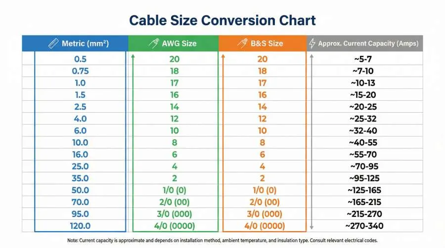
| Metric (mm²) | AWG Size | B&S Size | Diameter (mm) | Approx. Current (90°C Cu) | Common Applications |
|---|---|---|---|---|---|
| 0.5 mm² | 20 AWG | 20 B&S | 0.81 mm | 11 A | Electronics, signal wiring |
| 0.75 mm² | 18 AWG | 18 B&S | 1.02 mm | 16 A | Low-power circuits, lighting |
| 1.0 mm² | 17 AWG | 17 B&S | 1.15 mm | 19 A | Control circuits, small appliances |
| 1.5 mm² | 16 AWG | 16 B&S | 1.29 mm | 22 A | Lighting circuits, general use |
| 2.5 mm² | 14 AWG | 14 B&S | 1.63 mm | 32 A | Socket outlets, power circuits |
| 4.0 mm² | 12 AWG | 12 B&S | 2.05 mm | 41 A | Kitchen circuits, larger appliances |
| 6.0 mm² | 10 AWG | 10 B&S | 2.59 mm | 55 A | Air conditioning, cooker circuits |
| 10 mm² | 8 AWG | 8 B&S | 3.26 mm | 73 A | Sub-main distribution, machinery |
| 16 mm² | 6 AWG | 6 B&S | 4.12 mm | 101 A | Three-phase equipment, commercial |
| 25 mm² | 4 AWG | 4 B&S | 5.19 mm | 135 A | Industrial motors, main risers |
| 35 mm² | 2 AWG | 2 B&S | 6.54 mm | 181 A | Heavy machinery, distribution boards |
| 50 mm² | 1/0 AWG | 0 B&S | 8.25 mm | 245 A | Service entrance, large feeders |
| 70 mm² | 2/0 AWG | 00 B&S | 9.27 mm | 283 A | High-current industrial |
| 95 mm² | 3/0 AWG | 000 B&S | 10.40 mm | 328 A | Power distribution, substations |
| 120 mm² | 4/0 AWG | 0000 B&S | 11.68 mm | 380 A | Very high current applications |
Key Points
- Metric (mm²): Cross-sectional area, primary in IEC countries
- AWG/B&S: Inverse scale (smaller number = thicker wire)
- Conversion: Always choose next larger size for safety
- Applications: Typical uses for each size range
Keep this table handy for international equipment or sourcing cables.
How to Convert Between Cable Size Systems
Accurate conversion between mm², AWG, and B&S ensures safety and compliance. Our comparison table provides quick lookups, but understanding the principles helps with edge cases.
Practical Conversion Methods
- Use the Table: For most field work, our comparison table offers sufficient accuracy.
- Online Calculators: Websites like RapidTables or Engineering ToolBox provide instant conversion.
- Mobile Apps: Electrician apps often include wire gauge converters with derating factors.
- NEC Chapter 9, Table 8: Contains exact dimensions and areas for AWG and metric sizes.
The Golden Rule: Round Up, Never Down
If conversion gives 3.8 mm² for 12 AWG, don’t use 4.0 mm²—use 6.0 mm² (next standard size up). This compensates for manufacturing tolerances, different materials, installation conditions, and voltage drop.
Common Conversion Scenarios
- North American to European: 10 AWG ≈ 5.26 mm² → use 6.0 mm²
- Solar DC cables: 6 AWG battery cable (13.3 mm²) → closest metric is 16 mm² (check voltage drop)
- Legacy British drawings: 4/0 B&S = 4/0 AWG (107.22 mm²) → modern equivalent 120 mm²
When Exact Conversion Matters
- Terminal Blocks: Physical diameter must fit connectors
- Conduit Fill Calculations: Exact area determines cable count
- Resistance Matching: Parallel conductors need identical resistance
In these cases, consult manufacturer datasheets rather than general tables.
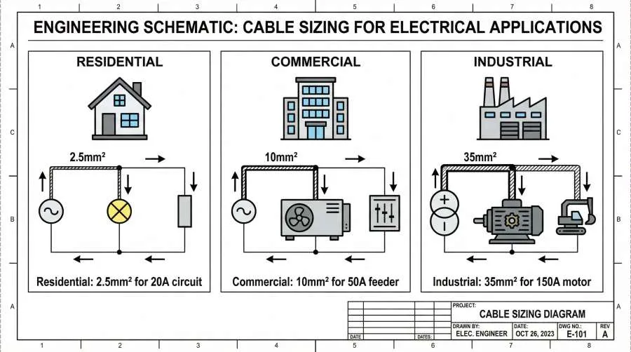
Selecting the Right Cable Size: Key Factors
Cable sizing requires balancing electrical requirements, installation conditions, and safety margins. Consider these key factors:
1. Current Carrying Capacity (Ampacity)
Calculate design current (I_b) from load power, voltage, and power factor. Apply correction factors for ambient temperature, cable grouping, thermal insulation, and protective device type to determine minimum cable size.
2. Voltage Drop
Limit drop to 3% for lighting, 5% for power circuits (NEC recommendations). Calculate using cable length, conductor resistance, and load current. For long runs, voltage drop often dictates size more than ampacity.
3. Installation Method
- Free air: Best cooling, highest ampacity
- Conduit/trunking: Reduced airflow, requires derating
- Buried direct: Soil thermal resistivity matters
- In insulation: Significant derating needed
4. Environmental Conditions
Consider temperature, moisture, chemical exposure, and mechanical protection requirements. Select appropriate insulation (THWN, XLPE, etc.) for the environment.
5. Standards and Codes
Comply with NEC (North America), IEC/BS (international), or local regulations. Use standard tables for ampacity and voltage drop calculations.
6. Future Expansion
Slight oversizing may save costly replacements if loads increase later.
7. Cost vs. Performance
Balance material cost against energy losses (I²R heating). Thicker cables cost more upfront but save energy over time.
By weighing these factors, you’ll select cables that are safe, efficient, and compliant.
Remember these key takeaways:
- Safety first: Always round up when converting between systems
- Standards matter: Follow NEC, IEC, or local codes as required
- Consider all factors: Current, voltage drop, environment, and future needs
- Verify with data: Use manufacturer specifications for critical applications
Whether you’re working on residential wiring, industrial machinery, or renewable energy systems, proper cable sizing prevents failures, saves energy, and protects lives. With the comparison tables and decision framework provided here, you’re equipped to make informed choices that meet both technical requirements and regulatory compliance.
For professional-grade electrical components designed to work seamlessly with correctly sized cables, explore VIOX Electric’s product range—where engineering precision meets real-world reliability.
