
It starts with a common scenario in industrial automation: a packaging line stops mid-shift. The maintenance technician traces the fault to a 24VDC solenoid valve that failed to close. Upon inspecting the control panel, they find the time delay relay driving that solenoid has stuck contacts. The relay is rated for 10 Amps, and the solenoid only draws 0.5 Amps. Why did a 10A relay fail on a 0.5A load?
This situation is a classic example of inductive load failure, a pervasive issue that costs manufacturing facilities thousands of dollars in downtime and replacement parts annually. While resistive loads like heaters and incandescent lamps are straightforward to switch, inductive loads—such as solenoid valves, motor brakes, contactor coils, and electromagnetic clutches—behave like compressed springs. When you release them (open the circuit), they release stored energy violently.
For senior electrical engineers and panel builders, understanding the physics behind this failure is critical. It is not a matter of quality control; it is a matter of physics and specification. The difference lies in understanding IEC 60947 utilization categories, specifically the critical distinction between AC-1 and AC-15 ratings. This article dissects why time relay contacts fail on inductive loads and provides the engineering frameworks to prevent it.
The Hidden Enemy: What Makes Inductive Loads So Destructive
To understand why contacts weld or erode, we must look at the nature of the load itself. Unlike resistive loads, where current and voltage are in phase and energy is dissipated as heat, inductive loads store energy in a magnetic field.
When a time relay energizes an inductive load (like a solenoid coil), current builds up to create a magnetic field. The real danger occurs when the relay contacts open to de-energize the load. According to Lenz’s Law, the collapsing magnetic field induces a voltage that opposes the change in current (V = -L · di/dt). Because the contact gap is opening rapidly (di/dt is very high), the inductor fights to keep the current flowing, generating a massive voltage spike known as inductive kickback or back EMF.
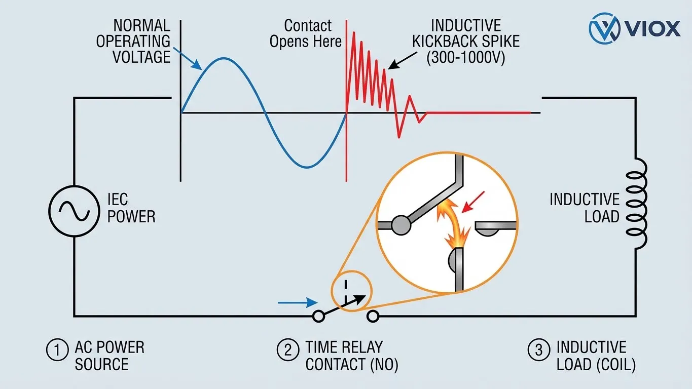
The Physics of Failure
- Voltage Spikes: Without suppression, a 24V coil can generate a spike of 300V to 1,000V. A 230V AC motor brake can generate spikes exceeding 3,000V.
- Arcing: This high voltage ionizes the air between the opening contacts, creating a plasma arc. This arc can reach temperatures of 5,000°C to 10,000°C—hotter than the surface of the sun.
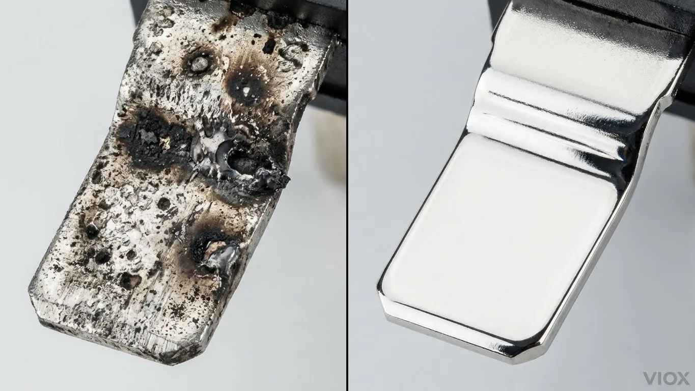
- Material Transfer: The intense heat melts microscopic portions of the silver alloy contact material. As the arc extinguishes and re-strikes (especially in AC circuits), molten metal is transferred between contacts, leaving pits and craters.
- Welding: If the relay is re-closed while the contacts are still molten or if the inrush current is too high during the “make” operation, the contacts fuse together. The next time the automation logic signals the relay to open, it physically cannot.
For a deeper dive into the differences between component ratings, see our guide on Circuit Protection Selection Frameworks.
Decoding IEC 60947-5-1: AC-1 vs. AC-15 Utilization Categories
The most common mistake in specifying time delay relays is looking only at the “Resistive Load” rating (often printed largest on the housing) and assuming it applies to all applications. The International Electrotechnical Commission (IEC) standard 60947-5-1 defines specific utilization categories that predict how a relay will perform under different electrical stresses.
The two most relevant categories for time relays are AC-1 and AC-15.
| Feature | AC-1 (Resistive / Low Inductive) | AC-15 (Electromagnetic Loads) |
|---|---|---|
| Primary Definition | Non-inductive or slightly inductive loads. | Control of AC electromagnetic loads greater than 72VA. |
| Power Factor (cos φ) | ≥ 0.95 | ≤ 0.3 (Testing condition) |
| Typical Applications | Resistive heaters, incandescent lighting, signaling lamps, pure resistance inputs. | Solenoid valves, contactor coils, magnetic brakes, electromagnetic clutches. |
| Make Current | 1x Rated Current (Ie) | 10x Rated Current (Ie) |
| Break Current | 1x Rated Current (Ie) | 1x Rated Current (Ie) |
| Break Voltage Stress | 1x Rated Voltage (Ue) | 1x Rated Voltage (Ue) + High Inductive Kickback |
| Contact Stress Level | Low. Arcing is minimal and easily extinguished. | Severe. Heavy inrush creates weld risks; inductive break creates heavy arcing. |
| Typical Electrical Life | 100,000+ operations at full load. | Often < 25,000 operations if wrongly specified; significantly reduced without suppression. |
Why the Difference Matters
A relay contact rated for 10A AC-1 might only be rated for 1.5A or 3A AC-15.
Relays built for AC-15 duty often feature:
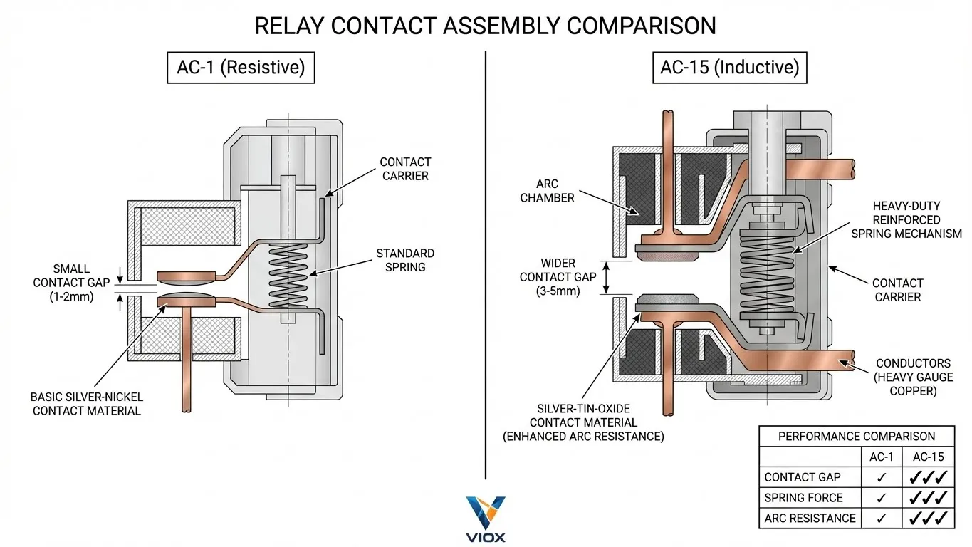
- Different Contact Materials: Using Silver-Tin-Oxide (AgSnO2) instead of Silver-Nickel (AgNi) to resist welding.
- Stronger Spring Mechanisms: To open contacts faster and extinguish arcs more rapidly.
- Wider Contact Gaps: To increase the dielectric strength between open contacts.
If you use an AC-1 rated relay to switch an AC-15 load, you are effectively driving a race car off-road. It may work for a few miles, but the suspension (or in this case, the contact surface) will eventually shatter.
Why Your Relay Contacts Are Failing: The 5 Root Causes
When analyzing returned merchandise or field failures at VIOX, we consistently trace the root cause to one of five factors.
Cause 1: Wrong Utilization Category Selection
This is the single most frequent error. An engineer sees “10A 250VAC” on the datasheet and connects a 5A solenoid valve. However, the 10A rating is strictly for resistive loads (AC-1). The inductive rating for that same relay might be only 2A. The 5A solenoid overloads the contact by 250% relative to its actual inductive capability.
Cause 2: Inrush Current Surge
Inductive loads, particularly AC solenoids and contactors, have low impedance when the magnet is open (air gap). They draw a massive inrush current—typically 5 to 10 times the steady-state “holding” current—to energize the magnet.
- The Failure: As the relay contacts close, they bounce microscopically. If this bounce happens during the 10x inrush peak, the intense heat creates a spot weld.
Cause 3: Inductive Kickback Voltage Spikes
As described in the “Hidden Enemy” section, the break operation is where the arc damage occurs.
- The Failure: Repeated arcing transfers metal from one contact to another (material migration). Eventually, the contacts either lock together mechanically due to surface roughness or erode so completely that they no longer make electrical connection.
Cause 4: Insufficient Arc Suppression
Many panel builders assume the relay’s internal air gap is sufficient to handle the arc. For AC-15 loads, it rarely is. Without external snubbers or varistors (MOVs), the arc persists for several milliseconds longer than necessary, drastically accelerating wear.
Cause 5: Environmental and Mechanical Factors
- High Duty Cycle: Rapid cycling (e.g., < 1 second intervals) prevents the contacts from cooling down between operations, leading to thermal runaway.
- Contamination: Dust or chemical vapors inside the panel can settle on contacts, increasing resistance and heat.
- Temperature: Operating relays above their rated ambient temperature derates their current carrying capacity. See our article on Electrical Derating Factors for more details.
How to Select the Right Time Relay Contact Rating
Selecting the correct relay requires a systematic approach. Do not guess—calculate.
Decision Matrix for Contact Selection
| Load Type | Load Characteristics | Recommended Contact Material | Derating Factor (vs AC-1) |
|---|---|---|---|
| Resistive Heater | Pure resistance, PF=1.0 | AgNi (Silver Nickel) | 1.0 (No derating) |
| Contactor Coil | High inrush, moderate inductance | AgSnO2 (Silver Tin Oxide) | 0.3 – 0.4 |
| Solenoid Valve | High inrush, high inductance | AgSnO2 | 0.2 – 0.3 |
| Motor Brake | Extreme inductance, severe kickback | AgSnO2 + External Contactor | 0.15 – 0.2 |
| Incandescent Lamp | High inrush (cold filament) | AgSnO2 (Silver Tin Oxide) | 0.1 (due to 10x inrush) |
Step-by-Step Selection Process
- Identify the Load: Is it a heater (AC-1) or a solenoid/motor (AC-15)?
- Determine Steady-State Current (Ihold): Check the load’s datasheet.
- Calculate Inrush Current (Iinrush): For inductive AC loads, assume 10 × Ihold.
- Check the Relay Datasheet: Look specifically for the AC-15 rating. If only AC-1 is listed, assume the AC-15 rating is 15-20% of the AC-1 rating.
- Verify Voltage: Ensure the relay voltage rating exceeds the system voltage.
- Select the Product: Choose a relay where the AC-15 rating > Load Ihold.
For robust industrial applications, we recommend VIOX industrial time relays, which are specifically tested and rated for AC-15 duty cycles.
Explore VIOX Time Delay Relays
Protection Strategies: Preventing Premature Contact Failure
Even with the right relay, inductive loads are punishing. Implementing protection strategies can extend contact life from 20,000 cycles to over 1,000,000 cycles.
Strategy 1: Use Properly Rated Contacts
Always specify contacts explicitly rated for AC-15 if your load is inductive. If the data sheet does not specify AC-15, do not use it for solenoids or motors without severe derating.
Strategy 2: Implement Arc Suppression
Suppression devices absorb the energy released by the magnetic field, preventing it from arcing across the relay contacts. These should always be installed in parallel with the load, not across the relay contacts (which can cause leakage current issues).
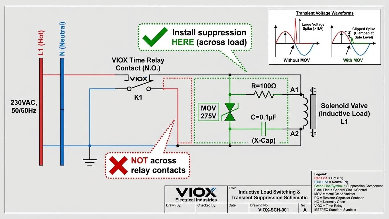
Technical Specifications for Arc Suppression
| System Voltage | Suppression Device | Recommended Specs | Installation Notes |
|---|---|---|---|
| 24 VDC | Freewheeling Diode | 1N4007 or similar | Cathode to positive. Slows drop-out time slightly. |
| 24 VAC | RC Snubber or MOV | MOV: ~30-40V clamping | Install directly at solenoid terminals. |
| 120 VAC | RC Snubber + MOV | MOV: 150-275V clamping | Capacitor: 0.1µF – 0.47µF, Resistor: 47Ω – 100Ω (1/2W) |
| 230 VAC | RC Snubber + MOV | MOV: 275-300V clamping | Capacitor: 0.1µF – 0.47µF (X2 rated), Resistor: 100Ω – 220Ω |
For a detailed comparison of suppression technologies, read our Freewheeling Diode vs. Surge Arrester Guide.
Strategy 3: Consider Zero-Crossing Switching
Solid-state relays (SSRs) or specialized electromechanical relays with zero-crossing circuits switch the load on or off when the AC sine wave voltage is at zero. This minimizes the energy available for an arc. While more expensive, this is highly effective for frequent cycling applications.
Strategy 4: Upsize and Derate
If you cannot add suppression, simply oversizing the relay is a valid strategy. If your load draws 2A, use a relay rated for 10A AC-15 (or a 10A AC-1 relay derated heavily). The larger contact surface area dissipates heat better and withstands erosion longer.
Strategy 5: Regular Maintenance
In critical applications (like power plant control or heavy manufacturing), include contact inspection in your maintenance schedule. Look for carbon buildup or pitting. Refer to our Industrial Contactor Maintenance Checklist for inspection protocols that also apply to heavy-duty relays.
Real-World Application Example
Scenario: An automation engineer needs to control a hydraulic solenoid valve using a time delay relay.
- Load: 230VAC Solenoid Valve
- Power: 150 VA (Volt-Amperes) holding power
- Control Voltage: 230VAC
Calculation:
- Steady State Current: I = P / V = 150 / 230 = 0.65 Amps.
- Inrush Current Estimate: 0.65 × 10 = 6.5 Amps.
- Load Category: Highly inductive (AC-15).
The “Standard” Mistake:
The engineer selects a cheap relay rated “5A 250VAC”.
- Hidden spec: That 5A is likely AC-1 (resistive).
- Real capability: The AC-15 rating is likely only ~0.5A to 1A.
- Result: The 6.5A inrush current is near the welding limit. The break arc will erode the contacts rapidly. Failure expected within weeks.
The VIOX Engineering Solution:
The engineer selects a VIOX Industrial Timer Relay.
- Spec Check: The datasheet lists “AC-15 Rating: 3A @ 230VAC”.
- Margin: 3A capability > 0.65A Load. (4.6x safety factor on holding current).
- Protection: The engineer installs a 275V MOV across the solenoid coil terminals.
- Result: Reliable operation for years.
Key Takeaways
- Inductive loads fight back: Solenoids and motors generate voltage spikes and arcs that destroy standard contacts.
- Know your categories: AC-1 is for resistive loads; AC-15 is for electromagnetic loads. Never confuse them.
- Derating is mandatory: If a relay only lists an AC-1 rating, derate it by 40-60% for inductive applications.
- Suppression is cheaper than downtime: A $0.50 MOV or RC snubber can save a $50 relay and $5,000 of production downtime.
- Check the Inrush: Always calculate the 10x inrush current for AC coils and ensure the relay’s “make” capacity can handle it.
- Verify with VIOX: When in doubt, consult VIOX time relay selection guides to match the specific product to your application.
Frequently Asked Questions (FAQ)
Q: Can I use an AC-1 rated relay for a small solenoid valve?
A: Only if you significantly derate the relay. For example, a 10A AC-1 relay might handle a 1A solenoid valve, but you must verify the manufacturer’s data for inductive switching life curves. Adding arc suppression is highly recommended.
Q: What is the difference between contact welding and contact erosion?
A: Welding usually happens during the “make” (closing) operation due to high inrush current melting the contacts, causing them to fuse. Erosion happens during the “break” (opening) operation due to arcing, which gradually burns away the contact material until connection is lost.
Q: Do I need a snubber if my relay is AC-15 rated?
A: While AC-15 relays are built to withstand arcs better, adding a snubber is still best practice. It eliminates the root cause of the arc (the voltage spike) rather than just resisting it, significantly extending the electrical life of the relay.
Q: How do I calculate the right MOV voltage rating?
A: Select an MOV with a Maximum Continuous Operating Voltage (MCOV) just above your highest expected line voltage. For 120VAC lines, a 150V MCOV is common. For 230VAC, use 275V or 300V. Do not size it too close to the nominal voltage, or normal line fluctuations might cause it to overheat.
Q: Why do my contacts fail even though the current is within rating?
A: You likely looked at the resistive (AC-1) rating but are switching an inductive load. Or, the environmental temperature is too high, requiring thermal derating. Check the utilization category on the datasheet.
Q: Can solid-state relays (SSRs) solve this problem?
A: Yes. Since SSRs have no moving parts, they cannot weld or erode mechanically. However, they are susceptible to damage from overvoltage spikes, so proper varistor protection is even more critical with SSRs than with electromechanical relays.
Q: Where can I find more information on wiring terminal blocks for these relays?
A: Proper termination is just as important as relay selection. Check our Terminal Block Selection Guide for best practices in panel wiring.
