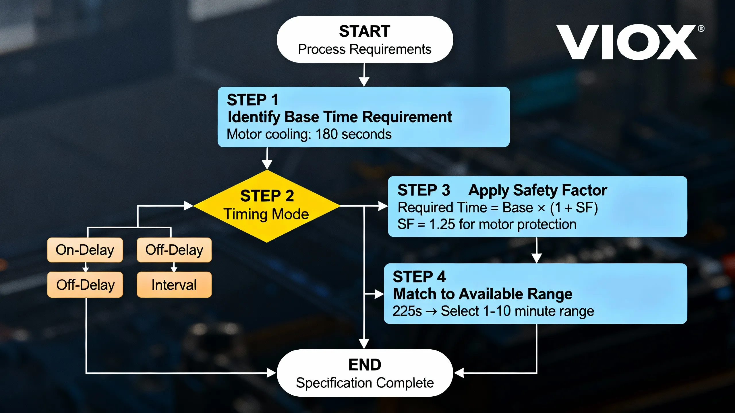
To calculate the correct time range for your timer relay, follow these four essential steps: identify your actual process timing requirements, select the appropriate timing mode (on-delay, off-delay, interval, or cyclic), apply safety factors to account for tolerance and environmental conditions, and match your calculated requirements to available commercial time ranges. This systematic approach helps your timer relay deliver reliable performance while avoiding common mistakes like insufficient margins or wrong mode selection that can lead to equipment damage or safety hazards.
Timer relays are critical control components in industrial automation, motor control, HVAC systems, and countless other applications where precise timing determines system reliability and safety. Selecting the wrong time range—whether too narrow or too broad—can cause operational failures, equipment damage, or compromised safety. This guide provides practical calculation methods, detailed examples, and quick-reference tables to help engineers and technicians confidently specify timer relay time ranges for any application.
Understanding Timer Relay Time Ranges
A timer relay’s time range refers to the adjustable span of timing values the device can provide, such as 0.1-1 second, 1-10 seconds, or 1-10 minutes. This differs from timing accuracy, which describes how precisely the relay achieves the set time value.
Time Range vs. Timing Accuracy
Understanding this distinction is crucial for proper specification:
| Characteristic | Definition | Example | Impact on Selection |
|---|---|---|---|
| Time Range | The span of adjustable timing values available | 6-60 seconds, 1-10 minutes | Must encompass your process requirements |
| Timing Accuracy | How close actual timing is to set value | ±5%, ±0.5% + 150ms | Critical for synchronized operations |
| Repeatability | Consistency of timing over multiple cycles | ±0.5%, ±1% | Important for predictable processes |
According to IEC 61812-1 (the principal international standard for industrial timer relays), timing accuracy is typically expressed as a percentage of the set value or full-scale range. For example, a timer with ±5% accuracy set to 10 seconds operates between 9.5 and 10.5 seconds.
Common Commercial Time Ranges
Industrial timer relays are manufactured with standardized time ranges to cover diverse applications:
| Time Range | Typical Increment | Common Applications | Relay Type |
|---|---|---|---|
| 0.1-1 second | 0.01s | High-speed processes, quick pulses, packaging | Electronic multi-function |
| 1-10 seconds | 0.1s | Machine sequencing, motor soft start | Standard electronic |
| 6-60 seconds | 1s | HVAC start delays, motor protection | Electromechanical/Electronic |
| 1-10 minutes | 6s or 0.1min | Lighting delays, ventilation, cooling fans | Multi-range electronic |
| 1-10 hours | 6min or 0.1hr | Long-duration processes, maintenance scheduling | Specialized timers |
| 10-300 hours | Variable | Extended cycle operations, calendar functions | Programmable timers |
Key Point: Your calculated time requirement must fall within a single available range. If your process needs 45 seconds of delay, you cannot use a 1-10 second range relay—you need a 6-60 second or 1-10 minute range.
Step-by-Step Time Range Calculation Method
Step 1: Identify Your Process Timing Requirements
Start by determining the actual timing your application needs. This requires analyzing your process or equipment specifications.
Questions to answer:
- What is the minimum time delay required for safe/proper operation?
- What is the maximum acceptable delay before it impacts the process?
- Are there multiple timing requirements (start, run, stop)?
- Does the timing repeat cyclically or occur once per trigger?
Example 1 – Motor Cooling Fan:
A 15 kW motor manufacturer specifies the cooling fan must run for “at least 3 minutes” after motor shutdown to prevent bearing damage.
- Base requirement: 3 minutes (180 seconds)
- Type: Off-delay (fan continues after motor stops)
Example 2 – Sequential Conveyor Start:
Conveyor belt A must start, then conveyor belt B starts “5-8 seconds later” to prevent product jamming.
- Base requirement: 5-8 seconds delay
- Type: On-delay (Belt B starts after delay)
Step 2: Select Appropriate Timing Mode
Different timing modes serve different functions. Selecting the wrong mode is a common mistake that renders calculations meaningless.
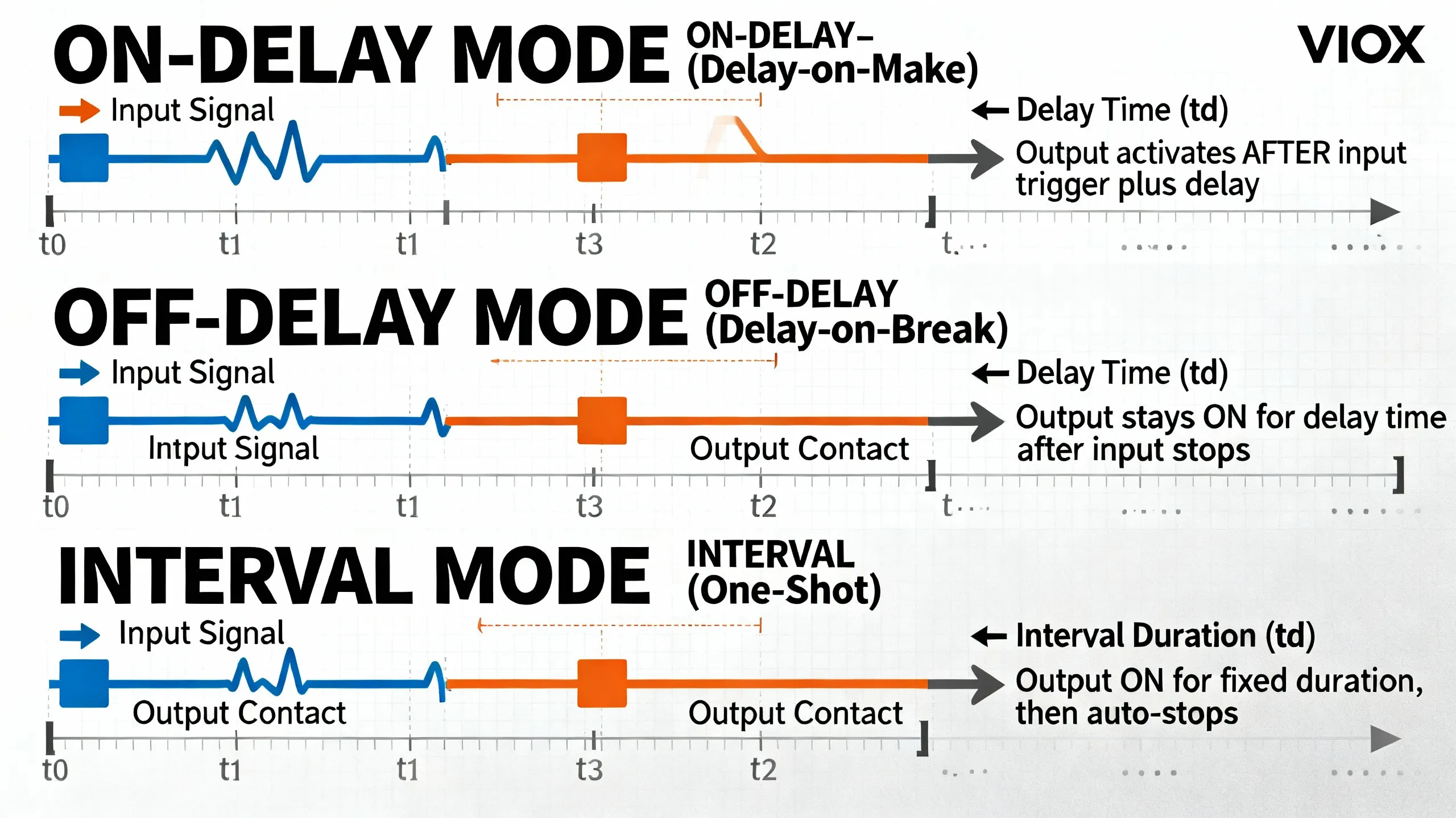
Timing Mode Decision Table
| If Your Application Needs… | Select Mode | Time Calculation Basis |
|---|---|---|
| Equipment to START after a delay following input trigger | On-Delay (Delay-on-Make) | Time from input ON to output ON |
| Equipment to CONTINUE running for a set time after input stops | Off-Delay (Delay-on-Break) | Time from input OFF to output OFF |
| Equipment to run for a fixed duration then automatically stop | Interval Timer (One-Shot) | Duration of output ON pulse |
| Equipment to cycle continuously between on and off states | Cyclic Timer | Both ON time and OFF time (may need 2 settings) |
| Star-Delta motor starting sequence control | Star-Delta Timer | Transition time from star to delta |
Common Mistake: Confusing on-delay with off-delay. When a cooling fan must run “5 minutes after equipment shuts down,” that’s off-delay, not on-delay.
Step 3: Apply Safety Factors and Margins
Don’t specify a timer relay time range that exactly matches your minimum requirement. Real-world conditions demand safety margins.
Safety Factor Formula
The general formula for calculating required timer specification is:
Required Time Range = Base Process Time × (1 + Safety Factor)
Where Safety Factor accounts for:
- Timing tolerance (relay accuracy)
- Environmental variations (temperature effects)
- Component aging (drift over years)
- Adjustment flexibility (fine-tuning during commissioning)
Recommended Safety Factors by Application Type
| Application Type | Safety Factor | Total Margin | Justification |
|---|---|---|---|
| Critical Safety Functions | 1.3-1.5 | +30-50% | Cannot tolerate timing failure; must account for worst-case conditions |
| Motor Protection | 1.2-1.3 | +20-30% | Thermal time constants vary; prevents nuisance trips or inadequate protection |
| Sequential Control | 1.15-1.25 | +15-25% | Allows synchronization adjustment; prevents collision/jamming |
| HVAC/Building Systems | 1.1-1.2 | +10-20% | Energy efficiency optimization; occupant comfort adjustment |
| Non-Critical Timing | 1.05-1.1 | +5-10% | Minimum margin for relay accuracy and adjustment |
Detailed Margin Breakdown
Component Tolerance Margin:
- Electronic timer accuracy: typically ±0.5% to ±5% (per IEC 61812-1)
- Add margin = Base Time × (Accuracy % × 2)
Environmental & Aging Margins:
- Temperature effects: ±0.01-0.03% per °C
- Component drift over 5-10 years: +1-2%
- Adjustment flexibility: 10-20%
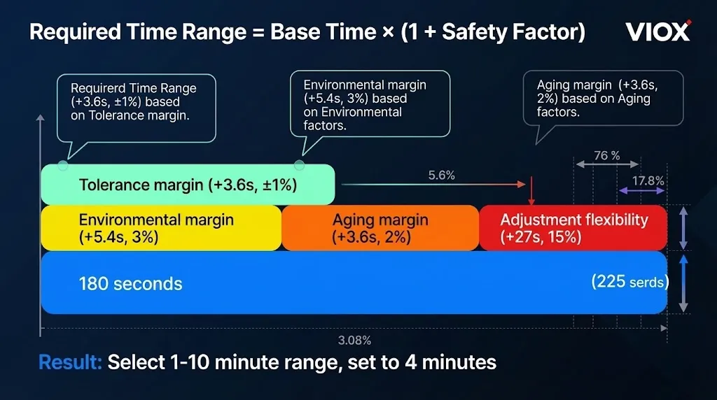
Example Calculation: Motor cooling fan (3 minutes base)
- Base time: 180 seconds
- Apply motor protection factor: 180s × 1.25 = 225 seconds
- Select 1-10 minute range, set to 4 minutes
Step 4: Match to Available Timer Relay Ranges
Once you’ve calculated your required time with safety margins, select a commercial timer relay whose range encompasses your specification.
Selection Decision Tree
If calculated time requirement falls within a single standard range:
✓ Select that range (e.g., 219s requirement → 1-10 minute range)
If calculated time falls between two ranges:
- Option 1: Select the next higher range for maximum adjustment flexibility
- Option 2: Select the lower range if it accommodates your maximum with margins
- Recommendation: Choose higher range unless cost or precision constraints apply
If calculated time exceeds standard ranges:
- Consider specialized extended-range timers (up to 300 hours)
- Evaluate programmable logic controllers (PLCs) for complex timing
- Use multiple timers in cascade configuration
Adjustability and Resolution Considerations
| Range Type | Resolution | Best For |
|---|---|---|
| Fixed time | None | Standardized processes |
| Dial adjustment | ~2-5% of scale | Field adjustment |
| Digital display | 0.1-1% | Precision applications |
Critical: A 1-10 minute dial with 10 positions only allows 1, 2, 3…10 minute settings.
Practical Calculation Examples
Example 1: Motor Cooling Fan Off-Delay
Application: Industrial compressor with cooling fan that must run after motor stops.
Requirements:
- Motor thermal specifications: minimum 180 seconds cooling time
- Environment: dusty factory, -10°C to +45°C
- Application criticality: High (bearing protection)
Calculation:
- Base process time: 180 seconds (3 minutes)
- Select timing mode: Off-delay (fan continues after motor stops)
- Apply safety factors:
- Motor protection factor: 1.25 (per table)
- 180s × 1.25 = 225 seconds (3.75 minutes)
- Match to range:
- Calculated: 225s falls in 1-10 minute range (60-600s)
- Select: 1-10 minute range timer
- Recommended setting: 4 minutes (240s) for comfortable margin
Specification: VIOX off-delay timer relay, 1-10 minute range, ≤±1% accuracy, AC/DC universal power supply
Example 2: Sequential Equipment Startup
Application: Chemical processing plant with three pumps that must start sequentially.
Requirements:
- Pump 1: starts immediately
- Pump 2: starts 8 seconds after Pump 1
- Pump 3: starts 8 seconds after Pump 2
- Reason: Prevent electrical demand spike
Calculation:
- Base process time: 8 seconds between starts
- Select timing mode: On-delay (each pump starts after delay)
- Apply safety factors:
- Sequential control factor: 1.2
- 8s × 1.2 = 9.6 seconds
- Match to range:
- Calculated: 9.6s fits in 1-10 second range
- Select: 1-10 second range timer (need 2 units)
- Recommended setting: 10 seconds for each delay
Specification: Two VIOX on-delay timer relays, 1-10 second range, digital adjustment, ≤±0.5% repeatability
Example 3: Cyclic Irrigation System
Application: Agricultural irrigation zone controller.
Requirements:
- Zone ON time: 12 minutes (water flow)
- Zone OFF time: 48 minutes (soil absorption)
- Cycles continuously during irrigation period
Calculation:
- Base process times: 12 min ON, 48 min OFF
- Select timing mode: Cyclic timer (asymmetric on/off)
- Apply safety factors:
- Non-critical application: 1.1 factor
- ON: 12 min × 1.1 = 13.2 min
- OFF: 48 min × 1.1 = 52.8 min
- Match to range:
- Both values fit in 1-10 minute range? No (52.8 > 60 min)
- Need: 1-10 hour range for OFF time
- Alternative: Use 10-100 minute range if available
- Recommended settings: ON = 15 min, OFF = 1 hour (compromise for standard range)
Specification: VIOX cyclic timer relay with dual adjustable ranges, or multi-function timer with separate ON/OFF time settings
Common Time Range Selection Mistakes
Avoiding these pitfalls ensures reliable timer relay performance:
| Mistake | Consequence | Solution |
|---|---|---|
| Specifying exact minimum time with no margin | Process fails when relay operates at lower tolerance limit (-5%) | Always add minimum 10% safety factor |
| Selecting wrong timing mode (on-delay instead of off-delay) | Equipment operates opposite of intended; complete system failure | Carefully analyze when output should activate/deactivate |
| Ignoring adjustment resolution | Cannot set precise required time; forced to use approximate value | Check datasheet for actual resolution (e.g., 10-position dial = 10% steps) |
| Overlooking environmental factors | Timing drifts significantly in temperature extremes | Add 2-3% margin for industrial environments, verify operating temp range |
| Using oversized range for precision applications | Poor resolution and accuracy at low end of range | Select smallest range that accommodates requirement with margins |
| Forgetting component aging | Timer drifts out of spec after 3-5 years | Add 2% aging margin for long-term installations |
| Not considering inrush/startup transients | Relay timing starts before equipment actually stabilizes | Add transient settling time to base requirement |
Real-World Example of Wrong Mode Selection:
An engineer specified an on-delay timer for a ventilation fan that needed to “run for 5 minutes after the process stops.” Result: The fan would start 5 minutes after the process started (on-delay), then run continuously. The correct choice was off-delay, which keeps the fan running for 5 minutes after the process stops.
Time Range Specification Quick Reference
By Industry Application
| Application Category | Typical Time Range Needed | Recommended Range | Timing Mode | Key Considerations |
|---|---|---|---|---|
| Motor Soft Start | 5-30 seconds | 1-10 seconds or 6-60 seconds | On-delay | Match to motor inertia; larger motors need longer |
| Motor Cooling/Run-On | 2-10 minutes | 1-10 minutes | Off-delay | Based on thermal time constant |
| Star-Delta Transition | 3-15 seconds | 1-10 seconds | Star-delta (specialized) | Per motor manufacturer specs |
| HVAC Sequential Start | 10-60 seconds | 6-60 seconds | On-delay | Stagger to reduce demand |
| Lighting Delay-Off | 30 seconds – 5 minutes | 1-10 minutes | Off-delay | Energy codes and user preference |
| Safety Interlock | 0.5-5 seconds | 0.1-1 second or 1-10 seconds | Interval or on-delay | Must meet safety standards (IEC 61508) |
| Conveyor Sequencing | 3-20 seconds | 1-10 seconds | On-delay | Based on product transfer time |
| Pump Alternation | 1-24 hours | 1-10 hours or programmable | Cyclic | Even wear distribution |
| Process Soaking Time | 5-60 minutes | 1-10 minutes or 1-10 hours | Interval | Recipe-dependent; use digital adjustment |
| Irrigation Zones | 5-30 minutes ON, 15-120 min OFF | 1-10 hours with dual settings | Cyclic | Soil type and plant requirements |
Quick Selection Guidelines
Standard Process:
- Calculate base time → add 20% safety factor → select next standard range
- Verify accuracy ≤±5% (general) or ≤±1% (critical)
Safety-Critical:
- Add 30-50% safety factor
- Specify ≤±1% accuracy and repeatability
- Document per ISO 13849 or IEC 61508
Frequently Asked Questions
How much safety margin should I add to my timer relay calculation?
For critical safety functions, add 30-50%. Motor protection needs 20-30%. Sequential control and HVAC require 15-25%. Even non-critical applications should have at least 10% margin.
What if my time requirement falls between two available timer ranges?
Select the next higher range. If you calculate 35 seconds (with margins), choose the 6-60 second range rather than the 1-10 second range for maximum adjustment flexibility.
Can I use a wider range timer relay for better flexibility?
Yes, but wider ranges may have lower resolution. A 1-10 minute timer might offer 0.1-minute precision, while a multi-range model might only provide 6-second precision. For precision applications, select the narrowest range that encompasses your requirement.
How accurate do timer relay calculations need to be?
Match rigor to criticality. Safety applications demand documented calculations per IEC 61508. Motor protection requires thermal analysis. General applications need basic calculations with 20% safety margin.
What factors affect actual timing in real installations?
Temperature (±0.01-0.03%/°C), supply voltage variations (±1-2%), component aging (+1-2% over 5-10 years), and EMI in noisy environments all affect timing. Safety margins absorb these variations.
How do I calculate time range for cyclic timers?
Calculate both ON and OFF times separately, apply 10-20% safety factors to each. Specify an asymmetric cyclic timer or use separate ON-delay and OFF-delay timers in series.
Should I account for contact switching time?
Usually no. Contact switching (5-20ms) is negligible for second-to-hour ranges. For high-speed applications (0.1-1 second range), check datasheets or use solid-state outputs (<1ms switching).
Conclusion
Calculating the correct time range for your timer relay is a systematic process that ensures reliable operation and prevents costly mistakes. The four-step methodology—identifying process timing requirements, selecting the appropriate timing mode, applying adequate safety factors, and matching to commercial ranges—provides a framework for confident specification decisions.
Remember that safety margins are not optional luxuries but essential provisions for real-world variations in tolerance, environment, and aging. A properly calculated timer relay specification accounts for worst-case conditions while providing adjustment flexibility during commissioning and operation.
For critical applications, always consult manufacturer specifications, verify accuracy and repeatability ratings per IEC 61812-1, and document your calculations for future reference. VIOX timer relays offer a comprehensive range of time ranges, high accuracy specifications, and flexible mounting options to meet diverse industrial, commercial, and automation requirements.
When in doubt, err on the side of larger safety margins and select quality components from reputable manufacturers. The small additional cost is insignificant compared to the expense of system downtime, equipment damage, or safety incidents caused by improper timer relay specifications.
