
Why Industrial Contactor Maintenance Can’t Be Ignored
Industrial contactors operate as the workhorses of electrical control systems, cycling thousands of times daily in motor control centers, HVAC systems, and manufacturing equipment. Yet two-thirds of contactor failures are preventable through routine maintenance—a statistic that translates into millions in avoided downtime costs annually.
When a contactor fails unexpectedly, the consequences cascade: production lines halt, critical HVAC systems shut down, and emergency service calls drain maintenance budgets. More critically, degraded contactors pose fire hazards and electrical shock risks. The difference between a facility that experiences 3 days of unexpected downtime per year versus 30 minutes often comes down to one factor: a documented preventive maintenance program.
This guide provides electrical contractors, facility managers, and maintenance engineers with actionable inspection procedures, replacement criteria, and scheduling frameworks proven to extend contactor service life while eliminating failure-related downtime.
Why Industrial Contactor Maintenance Matters
The True Cost of Contactor Failure
Equipment failures don’t announce themselves—they accumulate silently through thousands of switching cycles until a critical component fails. Research from electrical maintenance studies reveals that contactors without scheduled maintenance fail at 3× the rate of properly maintained units.
Consider the financial impact:
- Unplanned downtime: $5,000-$50,000 per hour depending on facility type
- Emergency service calls: 200-300% premium over scheduled maintenance
- Collateral damage: Motor burnout, process equipment damage, product waste
- Safety incidents: OSHA violations, worker injury liability, insurance claims
Safety Considerations
Degraded contactors present multiple safety hazards:
- Electrical arcing: Creates fire ignition sources and explosive atmospheres in hazardous locations
- Welded contacts: Prevent proper disconnection during emergencies, defeating lockout/tagout procedures
- Overheating: Insulation failure can energize equipment enclosures
- Contact erosion: Increases resistance, causing downstream equipment overheating
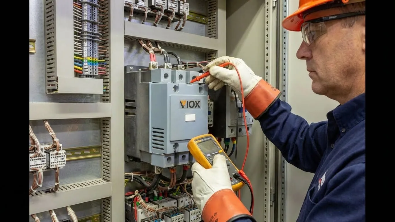
Before performing any maintenance, always follow proper LOTO procedures to de-energize circuits and verify zero-energy states.
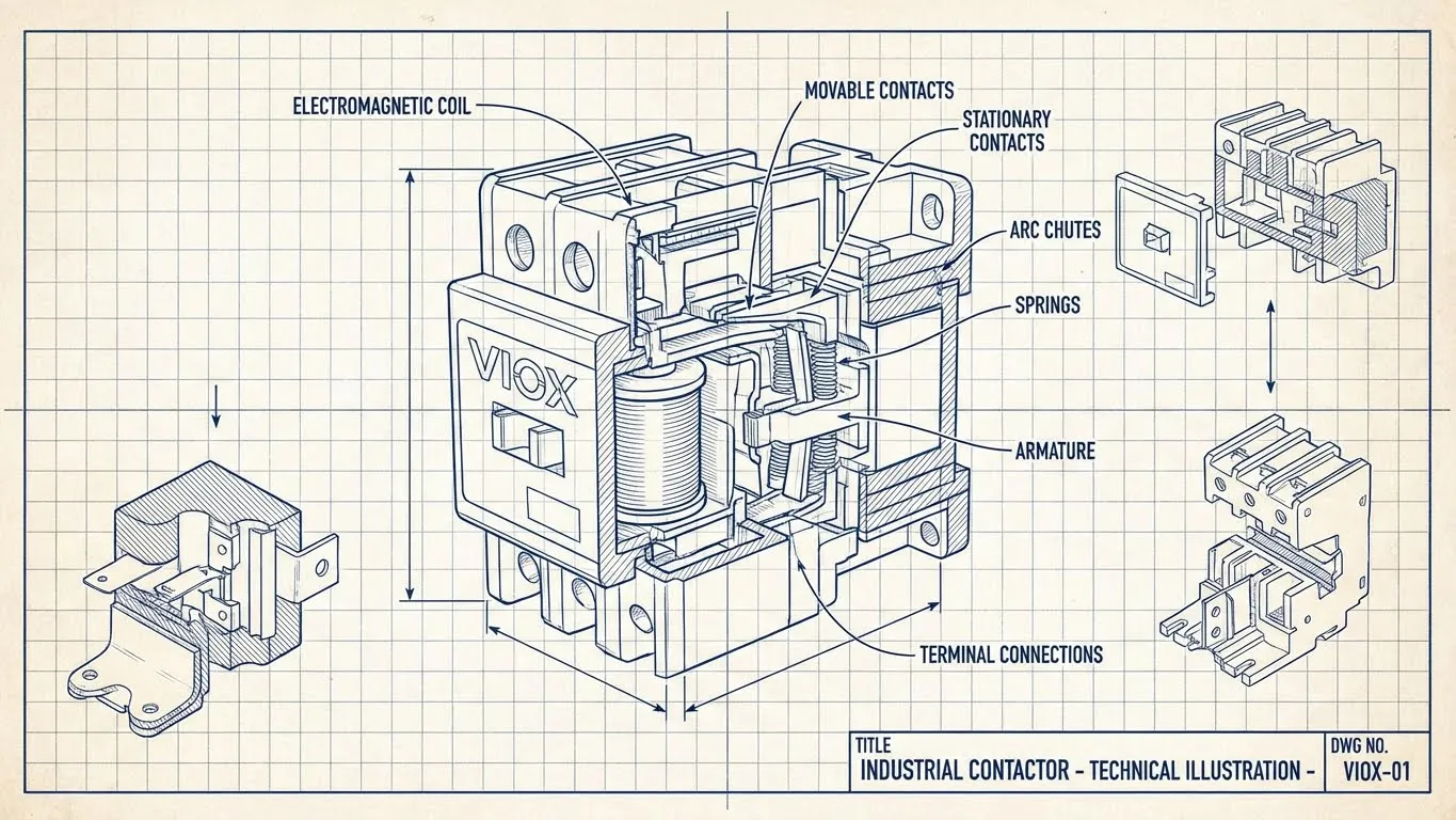
Understanding Contactor Lifespan
Not sure which contactor you have? Read What is a Contactor for component identification guidance.
Mechanical vs. Electrical Life
Industrial contactors have two distinct life ratings:
Mechanical Life: 1-10 million operations (no-load switching)
- Determined by spring fatigue, bearing wear, armature movement
- Rarely achieved in actual service conditions
- Typical rating: 1-5 million cycles for standard industrial contactors
Electrical Life: 100,000-1,000,000 operations (under rated load)
- Limited by contact erosion from electrical arcing
- Actual service life typically falls within this range
- Varies dramatically with load type (resistive vs. inductive)
Real-World Service Life: 5-15 years with proper maintenance
- AC-3 duty (motor control): 8-12 years typical
- AC-4 duty (plugging, jogging): 3-7 years typical
- 24/7 operations reduce lifespan by 30-40%
Factors Affecting Longevity
Operating Environment
- Temperature: Each 10°C above 40°C reduces life by ~50%
- Humidity: Accelerates corrosion; maintain <70% RH
- Contamination: Dust, metal particles, chemical vapors
- Vibration: Accelerates mechanical wear, causes loose connections
Electrical Stress
- Voltage fluctuations: ±10% coil voltage variation shortens life
- Inrush current: High motor starting currents increase contact erosion
- Switching frequency: Frequent cycling compounds electrical wear
- Load type: Highly inductive loads (motors, transformers) create severe arcing
Installation Quality
- Mounting position: Improper orientation affects arc extinction
- Connection torque: Under-tightened terminals increase resistance and heat
- Control voltage stability: Voltage drops below 85% prevent reliable operation
Complete Inspection Checklist
Systematic inspection catches problems before they cause failures. Organize your program by inspection frequency based on equipment criticality and operating conditions.
Daily Inspections (Energized Equipment)
Visual Observation (operators can perform)
- Listen for unusual sounds: humming, buzzing, chattering
- Check for visible overheating: discoloration, smoke, burning odor
- Observe operation: smooth engagement, proper dropout
- Verify indicator lights function correctly
- Note any unusual vibration or noise
Monthly Inspections (De-Energized Equipment)
Before starting any de-energized inspection, verify proper lockout/tagout procedures are in place.
Enclosure Inspection
- Check for proper sealing; ensure no moisture ingress
- Inspect for physical damage, corrosion, or deformation
- Verify ventilation openings are clear
- Confirm environmental conditions meet specifications
Visual Contact Inspection (without disassembly)
- Look for signs of arcing: black residue, pitting
- Check contact alignment through inspection window
- Verify no foreign material contamination
- Assess any visible contact wear or erosion
Connection Verification
- Inspect all terminal connections for tightness
- Check for corrosion, oxidation, or discoloration
- Look for signs of overheating: melted insulation, heat marks
- Verify wire insulation integrity near terminals
Quarterly Inspections (Detailed De-Energized)
Contact Examination (requires opening contactor)
- Measure contact resistance: typically <100 microhms for power contacts
- Assess pitting depth: replace if >50% of contact material eroded
- Check for welding, burning, or severe discoloration
- Verify contact wipe and pressure are within specifications
- Clean contacts using approved methods (fine abrasive cloth, no solvents)
Mechanical Component Checks
- Inspect springs for tension loss or breakage
- Check armature movement: smooth, no binding or hesitation
- Verify auxiliary contact operation and alignment
- Lubricate moving parts per manufacturer specifications
- Examine arc chute condition and alignment
Coil Testing
- Measure coil resistance: compare to nameplate values (±10% typical)
- Test insulation resistance: minimum 10 MΩ to ground
- Check for overheating signs: discoloration, varnish odor
- Verify proper coil voltage matches control circuit
- Test magnetic circuit air gap: typically 0.1-0.3mm closed
Annual Inspections (Comprehensive Evaluation)
Electrical Performance Testing
- Measure pickup voltage: should be 70-85% of rated coil voltage
- Measure dropout voltage: typically 20-40% of rated coil voltage
- Test contact closing time: typically 15-50ms depending on size
- Verify contact force using spring scale or gauge
- Perform insulation resistance testing at rated voltage +1000V
Thermal Imaging
- Scan all connections and contacts during operation
- Establish baseline temperature profiles
- Flag hotspots exceeding 10°C above ambient rise
- Compare thermal patterns to previous scans
Complete Operational Test
- Cycle contactor 10-20 times under no-load conditions
- Test under partial load if possible
- Verify interlocking and safety circuits function
- Check overload relay operation and calibration
Preventive Maintenance Schedule
Tailor this schedule to your specific operating conditions and equipment criticality. High-cycle or critical applications require more frequent inspection.
| Maintenance Task | Daily | Monthly | Quarterly | Annual |
|---|---|---|---|---|
| Visual/audible check during operation | ✓ | ✓ | ✓ | ✓ |
| Enclosure inspection | ✓ | ✓ | ✓ | |
| Connection tightness check | ✓ | ✓ | ✓ | |
| Contact visual inspection (external) | ✓ | ✓ | ✓ | |
| Contact resistance measurement | ✓ | ✓ | ||
| Contact wear assessment | ✓ | ✓ | ||
| Contact cleaning | ✓ | ✓ | ||
| Coil resistance measurement | ✓ | ✓ | ||
| Insulation resistance test | ✓ | |||
| Mechanical component inspection | ✓ | ✓ | ||
| Spring tension verification | ✓ | ✓ | ||
| Arc chute examination | ✓ | ✓ | ||
| Pickup/dropout voltage test | ✓ | |||
| Thermal imaging scan | ✓ | |||
| Complete operational cycle test | ✓ | |||
| Documentation update | ✓ | ✓ | ✓ | ✓ |
Adjust frequency for:
- High-cycle applications (>10 operations/hour): Increase quarterly to monthly
- Critical processes: Add redundancy and increase inspection frequency
- Harsh environments: Increase all inspection frequencies by 50%
- 24/7 operations: Increase annual to semi-annual
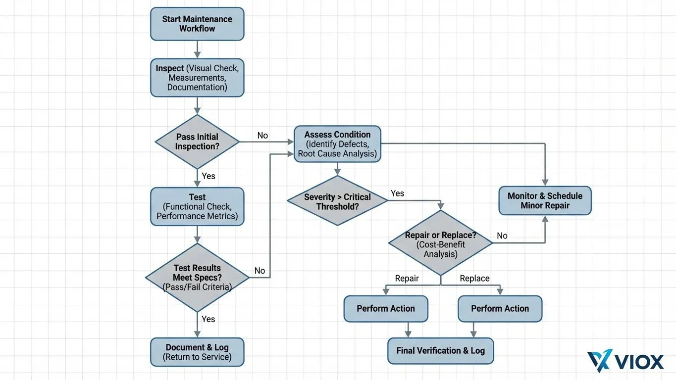
When to Replace vs. Repair
The replace-or-repair decision significantly impacts both immediate costs and long-term reliability. Use these criteria to make data-driven decisions.
Immediate Replacement Indicators
Replace the contactor immediately if you observe:
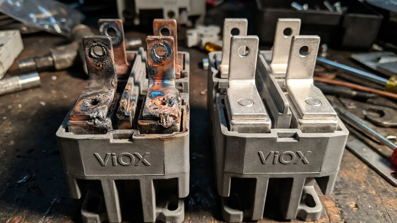
Critical Contact Damage
- Contact erosion exceeds 50% of original material thickness
- Welded contacts that require forced separation
- Severe pitting with craters deeper than 2mm
- Visible cracks in contact material
- Transfer of contact material between contacts
Coil Failure Signs
- Coil resistance deviates >15% from nameplate value
- Insulation resistance <1 MΩ to ground
- Visible coil damage: cracks, burns, melted insulation
- Coil draws excessive current (>110% rated)
- Intermittent or failed pickup at rated voltage
Mechanical Failures
- Broken or severely weakened springs
- Armature binding or excessive friction
- Broken mounting hardware or support structure
- Arc chute damage preventing proper arc extinction
- Auxiliary contact failure affecting control circuits
Age and Service History
- Equipment exceeds 15 years in service
- Multiple previous repairs within 2 years
- Contactor is obsolete with no replacement parts available
- Operating environment has changed significantly since installation
Suspect a fault? Use our Step-by-Step Testing Guide for comprehensive diagnostic procedures.
.webp)
Repair Considerations
Repairs may be cost-effective when:
Minor Contact Wear
- Pitting depth <1mm with >50% contact material remaining
- Light oxidation or discoloration cleaned successfully
- Contact resistance within acceptable limits (<100 microhms)
- No structural contact damage
Replaceable Components
- Spring assemblies available and easily replaced
- Auxiliary contacts modular and accessible
- Arc chutes can be cleaned or replaced
- Coil is serviceable and voltage-matched replacements exist
Cost Analysis Shows Value
- Repair cost <40% of replacement cost
- Equipment downtime for repair acceptable
- OEM or equivalent parts readily available
- Equipment expected to remain in service >3 years
Replace vs. Repair Decision Matrix
| Condition | Action | Justification |
|---|---|---|
| Contact erosion >50% | Replace | Insufficient material for safe operation |
| Coil resistance off by >15% | Replace | Indicates imminent coil failure |
| Spring tension <80% original | Repair | If springs replaceable and contactor otherwise sound |
| Age >12 years, moderate wear | Replace | Approaching end of service life; parts may be obsolete |
| Multiple components degraded | Replace | Cumulative repair costs approach replacement |
| Single failed auxiliary contact | Repair | If main contacts healthy and part available |
| Thermal damage to enclosure | Replace | Structural integrity compromised |
| Light contact oxidation only | Repair | Cleaning restores function |
Cost-Benefit Analysis
Replacement Costs (typical industrial contactor)
- New contactor: $150-$2,500 depending on size/rating
- Installation labor: 2-4 hours
- Downtime during replacement: 1-4 hours
- Total cost: $500-$5,000
Failure Costs (if not replaced when needed)
- Unplanned downtime: $5,000-$50,000+
- Emergency service call: 2-3× scheduled maintenance cost
- Collateral equipment damage: $5,000-$100,000+
- Safety incident potential: immeasurable
- Total risk: $10,000-$150,000+
The mathematics are clear: proactive replacement costs 10-30× less than failure-related costs.
Step-by-Step Maintenance Procedures
Contact Cleaning Procedure
Required Tools: Fine abrasive cloth (400-600 grit), contact cleaner (approved for electrical contacts), lint-free cloths, flashlight
Safety First: Verify LOTO procedures complete before starting.
Steps:
- Photograph contact condition before cleaning for documentation
- Remove loose debris with dry lint-free cloth
- Gently clean contacts with fine abrasive cloth using light pressure
- Remove only oxidation and light deposits—do not file or grind
- Clean with electrical contact cleaner to remove residue
- Dry completely before reassembly
- Measure contact resistance post-cleaning
- Document results and compare to baseline
Warning: Never use metal files, emery cloth, or aggressive solvents that damage contact plating.
Coil Resistance Testing Procedure
Required Tools: Digital multimeter (0.1Ω resolution), clamp meter, insulation tester (megohmmeter)
Steps:
- Disconnect coil power supply wires
- Set multimeter to lowest resistance range
- Measure across coil terminals
- Record reading and compare to nameplate value (±10% acceptable)
- Test insulation resistance from coil to ground (>10 MΩ required)
- Measure coil current during operation (should match nameplate ±10%)
- Check for voltage drop across supply wires during pickup
- Document all measurements with date/time stamp
Interpretation:
- Resistance high: Partial turn-to-turn short or corrosion
- Resistance low: Shorted turns or moisture ingress
- Insulation resistance low: Coil insulation breakdown—replace immediately
Connection Torque Verification
Required Tools: Calibrated torque wrench, manufacturer torque specifications, inspection mirror
Steps:
- Identify terminal size and type
- Obtain correct torque specification (typically 8-40 N·m depending on size)
- Loosen each connection 1/4 turn
- Re-torque to specification using calibrated wrench
- Verify no strand damage or wire movement
- Apply torque seal or mark for future verification
- Document torque values and any corrective actions
Critical: Under-torqued connections are the leading cause of contactor overheating failures.
Maintenance Best Practices
Documentation Requirements
Maintain comprehensive maintenance records including:
- Baseline data: Initial measurements at commissioning
- Inspection logs: Date, inspector, findings, measurements
- Trend analysis: Contact resistance over time, coil resistance trends
- Maintenance actions: Repairs, cleaning, adjustments performed
- Replacement history: Date, reason, new equipment details
- Failure reports: Root cause analysis for any failures
Digital CMMS (Computerized Maintenance Management System) platforms streamline documentation and enable predictive analytics.
Safety Protocols
Before any contactor maintenance:
- Complete written lockout/tagout procedure
- Verify zero-energy state with approved voltage tester
- Ground equipment to discharge residual capacitance
- Use appropriate PPE: insulated gloves, safety glasses, arc-rated clothing
- Establish hot work permits if required
- Ensure second person available for emergency response
During maintenance:
- Never bypass interlocks or safety devices
- Use insulated tools rated for voltage levels present
- Maintain proper approach distances for voltage level
- Verify test equipment calibration current
- Follow arc flash boundary requirements
Training and Qualifications
Maintenance personnel should possess:
- Electrical qualifications: Journeyman electrician or equivalent
- Safety training: NFPA 70E, arc flash awareness, LOTO certification
- Equipment-specific knowledge: Manufacturer training when available
- Test equipment proficiency: Multimeter, insulation tester, thermal camera
- Documentation skills: Accurate record-keeping and reporting
Predictive Maintenance Technologies
Advanced facilities can implement:
- Thermal imaging programs: Detect hotspots before failure (10-15°C rise = investigate)
- Vibration analysis: Identify bearing wear and mechanical degradation
- Current signature analysis: Detect abnormal load patterns
- Automated monitoring: IoT sensors track contact resistance, temperature continuously
- AI/ML analytics: Predict failure windows based on operating data
Reactive vs. Preventive Maintenance: The Real Numbers
| Factor | Reactive Maintenance | Preventive Maintenance |
|---|---|---|
| Maintenance Cost | 3-4× higher (emergency rates) | Baseline cost |
| Downtime Impact | 3-5 days unplanned per year | <30 minutes planned per year |
| Equipment Lifespan | 5-8 years average | 10-15 years average |
| Failure Rate | 3× higher | Baseline |
| Safety Incidents | Significantly higher risk | Minimized through proactive inspection |
| Parts Availability | Emergency procurement premium | Planned ordering, bulk discounts |
| Labor Efficiency | Rushed troubleshooting | Organized, methodical procedures |
| Total Cost (5-year) | $25,000-$75,000 per contactor | $8,000-$15,000 per contactor |
| ROI | Negative | 3-5× positive return |
Bottom line: Every dollar invested in preventive maintenance returns $3-5 in avoided failure costs.
Common Issues and Solutions
For detailed troubleshooting procedures, refer to our Common Contactor Problems & Troubleshooting Guide.
Humming or buzzing: Usually indicates low coil voltage, misalignment, or contamination. Measure coil voltage under load—should be 85-110% rated. Clean and realign components.
Chattering: Loose mounting, foreign objects preventing full closure, or voltage fluctuation. Verify mounting hardware torque, inspect for obstructions, stabilize control voltage.
Overheating: High resistance connections, oversized load, poor ventilation, or degraded contacts. Check terminal torque, verify load current vs. rating, improve airflow, measure contact resistance.
Failure to close: Coil failure, mechanical binding, or control circuit issue. Test coil resistance and insulation, verify free armature movement, troubleshoot control circuit.
Contacts welding: Excessive inrush current, improper sizing, or end-of-life wear. Verify contactor rated for application, consider contactor vs. motor starter selection, replace if near service life limit.
Frequently Asked Questions
How often should industrial contactors be replaced?
Industrial contactors typically last 8-12 years with proper maintenance in AC-3 motor control applications. However, replacement timing depends on operating conditions rather than age alone. Replace immediately if contact erosion exceeds 50%, coil resistance deviates >15%, or insulation resistance drops below 1 MΩ. High-cycle applications (>10 operations/hour) may require replacement every 3-7 years. Annual inspections with contact resistance trending provide the most reliable replacement timing guidance.
What are the signs a contactor needs immediate replacement?
Critical warning signs requiring immediate replacement include: welded contacts that don’t separate freely, contact erosion exceeding 50% of original material, visible cracks or severe pitting >2mm deep in contacts, coil resistance deviation >15% from nameplate, insulation resistance <1 MΩ to ground, broken or severely weakened springs, armature binding or excessive friction, and any burning odor or visible smoke. Additionally, contactors showing multiple degraded components or exceeding 15 years service should be replaced proactively.
Can I clean contactor contacts instead of replacing them?
Yes, contact cleaning is effective for light oxidation and minor deposits when contact material remains >50% original thickness and pitting is <1mm deep. Use fine abrasive cloth (400-600 grit) with light pressure—never metal files or emery cloth that damage contact plating. Clean only until oxidation is removed. Measure contact resistance post-cleaning (<100 microhms acceptable). However, contacts with deep pitting, material transfer, welding, or severe erosion require contactor replacement. Cleaning provides temporary improvement but doesn’t restore original performance.
How do I measure contactor contact wear?
Measure contact wear using these methods: Visual inspection with magnification to assess pitting depth and material remaining (compare to new contacts when possible). Measure contact resistance using a low-resistance ohmmeter—readings >100 microhms indicate significant wear. Use a depth gauge or micrometer to measure remaining contact thickness compared to new specifications (>50% remaining is acceptable). Thermal imaging during operation reveals hotspots from increased resistance. Document measurements over time to trend degradation rate and predict replacement timing.
What causes contactors to fail prematurely?
Premature contactor failure stems from: operating environment issues (temperature >40°C, humidity >70%, contamination, vibration), electrical stress factors (voltage fluctuations >±10%, excessive inrush current, high switching frequency, highly inductive loads), and installation problems (improper mounting orientation, under-torqued connections, inadequate control voltage). Additionally, undersizing for the application, lack of preventive maintenance, and contamination from metal particles or chemical vapors accelerate failure. Address these root causes rather than simply replacing failed units.
Is contactor maintenance worth the cost?
Absolutely—preventive maintenance delivers 3-5× ROI through avoided failure costs. A comprehensive 5-year preventive program costs $8,000-$15,000 per contactor, while reactive maintenance totals $25,000-$75,000 in emergency repairs, downtime, and collateral damage. Each hour of unplanned downtime costs $5,000-$50,000 depending on facility type. Maintenance also extends equipment life from 5-8 years (reactive) to 10-15 years (preventive), reduces safety incident risk, and enables planned parts procurement at better pricing. The mathematics clearly favor systematic preventive maintenance programs.
What tools do I need for contactor maintenance?
Essential tools include: digital multimeter with 0.1Ω resolution for resistance measurement, insulation tester (megohmmeter) rated to 1000V, calibrated torque wrench with appropriate sockets, thermal imaging camera for hotspot detection, fine abrasive cloth (400-600 grit) for contact cleaning, electrical contact cleaner (approved for contacts), flashlight and inspection mirror, depth gauge or micrometer for wear measurement, spring tension gauge, and documentation tools (camera, maintenance logs). Advanced programs benefit from vibration analyzers and current signature analysis equipment. All test equipment requires annual calibration certification.
Next Steps for Your Maintenance Program
Implementing a comprehensive contactor maintenance program requires commitment but delivers measurable ROI. Start by:
- Conducting baseline assessments of all critical contactors
- Establishing documentation systems for maintenance tracking
- Training personnel on proper inspection and testing procedures
- Scheduling preventive maintenance based on equipment criticality
- Sourcing replacement parts proactively for critical applications
VIOX Electric manufactures industrial contactors engineered for extended service life in demanding applications. Our technical support team provides maintenance guidance, replacement recommendations, and comprehensive product documentation to support your preventive maintenance program.
Contact VIOX Electric today for contactor selection assistance or to discuss your specific maintenance challenges.
