Bu sayfada
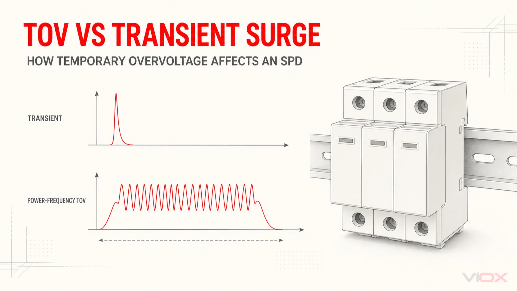
Bir AC aşırı gerilim koruma cihazı (SPD) is designed primarily to limit geçici aşırı gerilimler and divert surge current. A temporary power-frequency overvoltage (TOV) lasts much longer and can thermally overstress an SPD, especially one that uses metal-oxide varistors (MOVs). A TOV declaration describes the device’s behavior only for the stated voltage, duration, protection mode, and test condition. It does not turn the SPD into a voltage regulator or a universal protector against neutral loss or sustained overvoltage.
This distinction matters when selecting an SPD and when investigating a module that disconnects or fails repeatedly. A higher surge-current rating in kA does not, by itself, prove better TOV behavior.
Önemli Çıkarımlar
- Transient surge and TOV are different stresses. Standardized surge waveforms act on a microsecond timescale; TOV is a power-frequency condition assessed with a stated voltage and duration.
- Read the complete TOV declaration. The voltage value alone is incomplete without time, protection mode, system condition, and the declared outcome.
- Uc, Up, and TOV answer different questions. Uc or MCOV covers continuous voltage compatibility, Up describes surge-voltage limitation under specified tests, and the TOV declaration describes behavior during a temporary power-frequency overvoltage.
- Withstand and safe failure are not equivalent. Withstand means continued service under the declared test; safe failure means the SPD may leave service in a controlled manner.
- Correct the system cause. If repeated SPD failures are associated with neutral, earthing, voltage-selection, or supply problems, replacing the cartridge alone may repeat the failure.
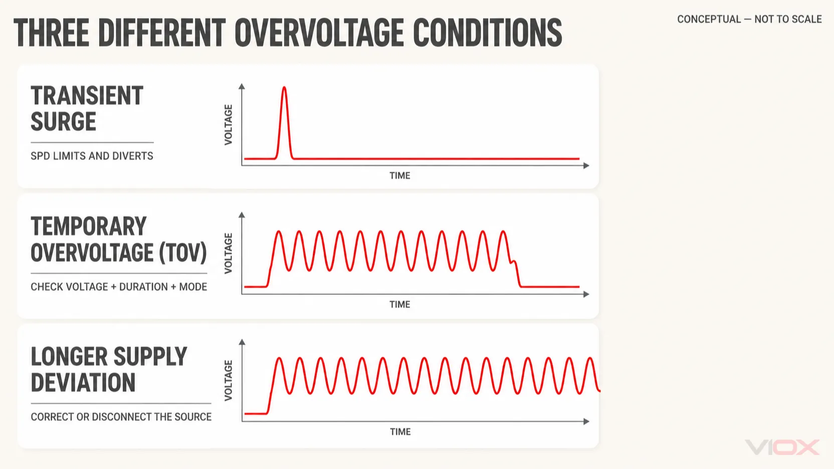
Transient Surge, TOV, and Sustained Overvoltage Are Not Interchangeable
The term “overvoltage” covers events with very different causes, durations, and protection responses. Classify the event before deciding what the SPD should do.
| Koşul | Typical electrical character | Main SPD implication | Appropriate engineering response |
|---|---|---|---|
| Transient surge | Short-duration impulse associated with lightning effects, switching, or another transient source | The SPD limits voltage and diverts impulse current within its declared test duty | Select and coordinate the correct SPD Type, voltage ratings, protection modes, and installation path |
| Temporary power-frequency overvoltage | Elevated voltage at or near system frequency for a specified temporary duration | The SPD may withstand it, disconnect safely, or be damaged, depending on its declared TOV behavior and application | Check the exact TOV declaration, system fault condition, earthing arrangement, and protection mode |
| Longer supply deviation or permanent overvoltage | Voltage remains outside the intended operating range beyond the temporary event under review | A conventional SPD is not a voltage regulator and should not be assumed to disconnect the protected load | Correct the supply fault or use a purpose-designed monitoring, regulation, or disconnection function under applicable rules |
The boundary is functional, not merely linguistic. IEC 61643-01:2024 defines common requirements, tests, ratings, and safety provisions for low-voltage SPDs intended to limit surge voltages and divert surge currents. IEC 61643-11:2025 applies those principles to AC low-voltage power SPDs and explicitly identifies expected fault conditions, including TOV stresses, as application considerations. Part 11 is intended to be read with the latest IEC 61643-01.
Why a TOV Can Overstress an MOV-Based SPD
An MOV is a nonlinear component. At normal voltage, it should conduct only a very small current. As voltage across the MOV rises into its conductive region, current increases sharply. That behavior is useful for a brief surge because it creates a low-impedance diversion path for impulse current.
During a TOV, the stress can persist for far longer than a transient impulse. If the applied power-frequency voltage drives significant current through the MOV, electrical energy is converted into heat. The result depends on several linked variables:
voltage across the protection mode → MOV current → power dissipation → temperature rise → disconnector response or material damage
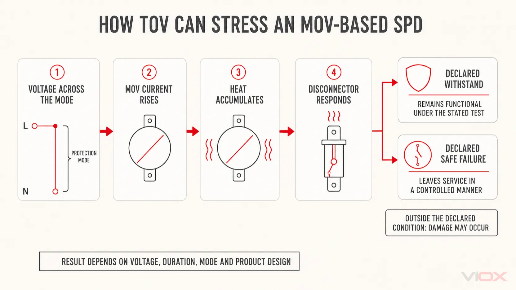
This is why an SPD cannot be evaluated from Imax, In, or Iimp alone. Those ratings describe defined surge-current duties; they do not substitute for the product’s TOV declaration.
Not every SPD uses the same internal technology or disconnecting arrangement. An internal thermal disconnector is commonly intended to remove an overheated protection component from service, but it is not automatically the same function as external short-circuit protection. The exact fault behavior, backup protection, and status indication must come from the product documentation. The SPD veri sayfası kılavuzunu bu beyanların nasıl bir araya geldiğini açıklar.
The Variables That Determine TOV Behavior
A statement such as “this SPD withstands TOV” is incomplete unless the applicable condition is identified.
| Değişken | Why it changes the result | Ne doğrulanmalı |
|---|---|---|
| Voltage magnitude | Higher voltage can move a voltage-limiting component further into conduction | Declared TOV voltage and reference voltage basis |
| Süre | Thermal energy and disconnector response depend on how long the condition remains | Stated test duration; never compare voltage values without time |
| Koruma modu | L-N, L-PE, N-PE, and L-L paths can experience different voltages during a fault | The exact mode covered by the declaration |
| Topraklama sistemi | TN, TT, and IT arrangements produce different fault-voltage conditions | System configuration at the actual installation point |
| Source and fault condition | Transformer connection, neutral condition, fault clearing, and source behavior affect the applied stress | Expected system and fault conditions, not nominal voltage alone |
| Uc veya MCOV | Continuous voltage compatibility establishes the normal operating boundary | Uc for each connected mode and the highest expected normal power-frequency voltage |
| Internal disconnector | Different designs can remain connected, disconnect, or reach a safe end state differently | Manufacturer’s TOV behavior and failure indication |
| External protection | A backup fuse or circuit breaker addresses specified fault-current conditions, not every overvoltage condition | Manufacturer coordination table and applicable short-circuit declaration |
IEC 61643-12:2020 addresses AC power SPD selection, operation, location, and coordination. It should be used alongside the product standard and the installation rules applicable to the target market.
How to Read Uc, Up, and the TOV Declaration Together
These parameters describe different parts of the same application; they are not interchangeable rankings.
Uc or MCOV: continuous voltage compatibility
Uc is the maximum continuous operating voltage stated for an IEC SPD under defined conditions. North American documentation commonly uses MCOV. It must be suitable for the voltage continuously present across each connected protection mode, including credible normal variation.
Uc should not be selected by applying a universal TOV multiplier. System voltage, earthing arrangement, protection mode, source behavior, product instructions, and applicable rules must be considered together. For the broader parameter boundary, see SPD'de Uc ve Up karşılaştırması.
Up: surge-voltage limitation
Yukarı is the declared voltage protection level obtained under specified standardized tests. It helps with insulation coordination, but the voltage that reaches equipment also depends on connection lead inductance, layout, upstream and downstream coordination, and the actual surge.
A low Up does not prove that an SPD will withstand a particular TOV. Conversely, selecting an unnecessarily high Uc solely to avoid TOV stress can change the surge-protection tradeoff. Both ratings must suit the same installation.
UT or TOV behavior: temporary fault response
A usable TOV entry should identify, directly or through the referenced product standard and instructions:
- the applied power-frequency voltage;
- the duration;
- the protection mode or terminal relationship;
- the relevant system or fault condition;
- whether the result is withstand, safe failure, or another precisely defined outcome;
- any required external protective device or installation condition.
For example, a manufacturer may publish a model-specific declaration such as a stated voltage for a stated number of minutes with a “withstand” outcome. That declaration applies to that model and condition only. It must not be copied into a generic specification for another SPD.
TOV Withstand vs Safe Failure
The two outcomes answer different engineering questions.
| Declared behavior | Pratik anlam | Kanıtlamadığı durumlar |
|---|---|---|
| Dayanım | The SPD remains capable of its intended function after the specified TOV test, subject to the standard and product declaration | Survival at every higher voltage, longer duration, different mode, or different source condition |
| Safe failure | The SPD is permitted to leave service in a controlled manner under the specified condition without creating an unacceptable hazard under the test requirements | Continued surge protection after the event |
After safe failure or disconnection, the installation may still be energized while surge protection has been lost. Status indication and remote signaling therefore matter in industrial and unattended systems. A green indicator before the event does not prove that every protective path remains available afterward; inspect the model-defined indication and maintenance instructions.
Research published through the US National Institute of Standards and Technology (NIST) describes the central design conflict: an SPD must conduct strongly enough to limit a short surge without attempting to clamp a longer power-frequency overvoltage indefinitely. The observed response of commercial SPDs under TOV stress ranged from no damage to destructive failure, reinforcing the need for declared and tested behavior rather than assumptions. See TOV Effects on Surge-Protective Devices ve The Dilemma of Surge Protection vs. Overvoltage Scenarios.
Neutral Interruption: An Important but System-Dependent Example
Neutral interruption is often used to explain TOV because, in a multi-phase system with phase-to-neutral loads, a displaced or open neutral can change the voltage seen by individual loads. The actual voltage depends on system topology, the point of interruption, load imbalance, earthing and bonding, and the remaining circuit paths.
An SPD connected between line and neutral may respond if its conduction region is reached, but it is not a controlled voltage regulator. Attempting to hold an abnormal power-frequency voltage can overheat its voltage-limiting components or operate its disconnector. It should not be treated as a temporary substitute for repairing the neutral or for a purpose-designed overvoltage monitoring and disconnection scheme.
The correct response is therefore not “install a larger-kA SPD.” It is to:
- isolate and correct the neutral or supply fault using qualified personnel;
- verify the voltage across every connected protection mode;
- check the SPD’s Uc and TOV declaration against the actual system;
- inspect its status and replace or service it if the manufacturer-defined indication requires action;
- determine whether a separate voltage-monitoring or permanent-overvoltage protection function is required by the system design or local installation rules.
Bu voltage protector vs surge protector comparison explains the functional difference between fast transient diversion and monitored disconnection for out-of-range supply voltage.
A Practical TOV Decision Framework
Use this sequence when specifying a new SPD or investigating repeated disconnection. It is a design and documentation framework, not an energized test procedure.
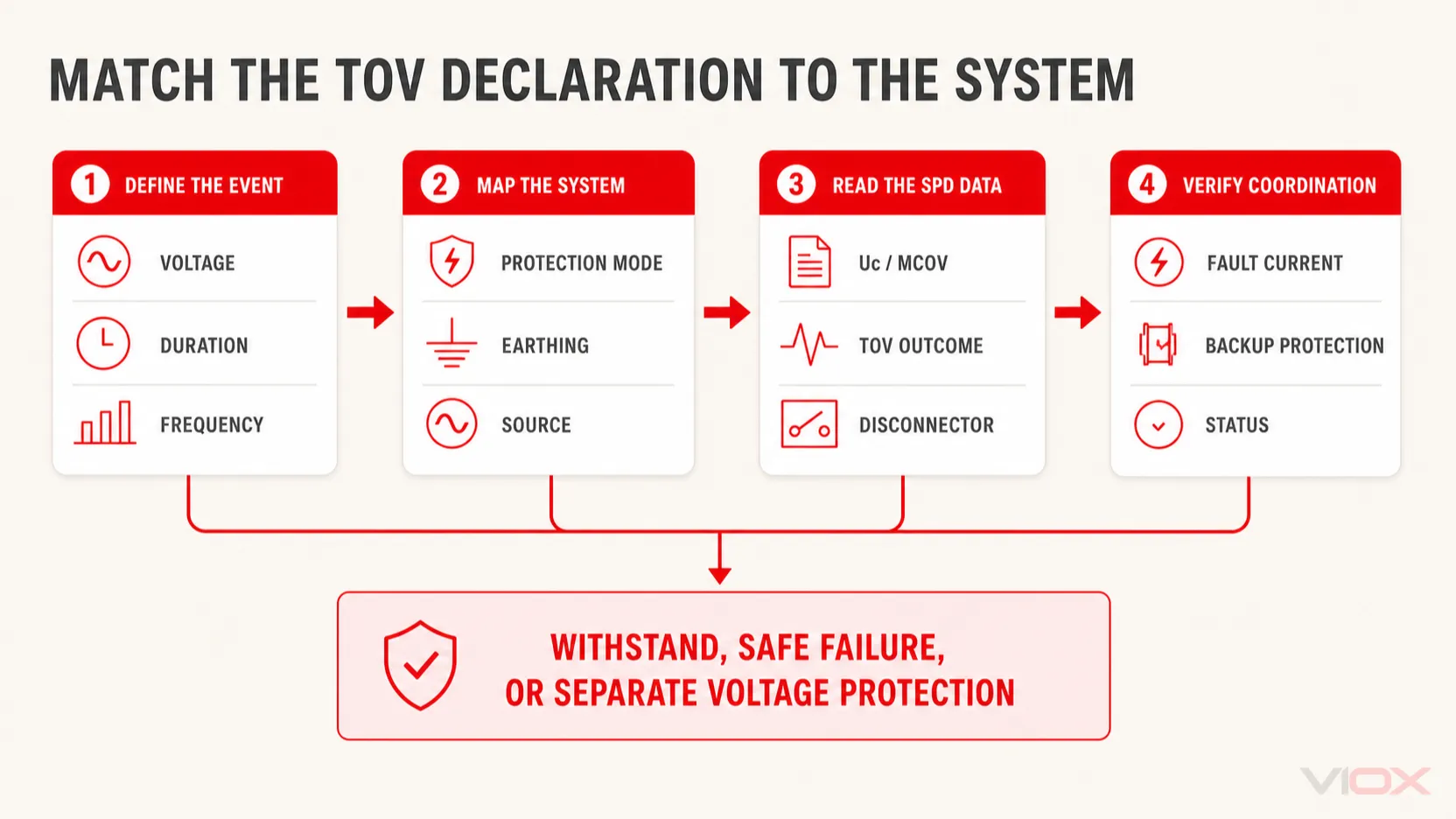
1. Define the event before selecting the device
Record the measured or calculated voltage, frequency, duration, affected conductors, repetition pattern, and operating state. Do not label every high-voltage event a “surge.”
2. Map the voltage by protection mode
Identify the voltage that can appear across L-N, L-PE, N-PE, or L-L for the actual topology. A device-level rating is meaningful only when mapped to its connected mode.
3. Confirm the earthing and source arrangement
Document the TN, TT, or IT arrangement, transformer winding connection, neutral treatment, generator or converter source, and likely fault-clearing path. A nominal “230/400 V” or “277/480 V” label is not enough to determine every fault-mode voltage.
4. Check Uc before TOV behavior
Verify that normal continuous voltage, including credible operating variation, does not exceed Uc for any protection mode. If it does, the application is already outside the intended continuous-voltage boundary.
5. Match the complete TOV declaration
Compare voltage, duration, mode, system condition, and declared outcome. Do not interpolate a universal pass/fail curve from one published point unless the manufacturer provides that curve or method.
6. Verify fault-current and disconnection coordination
Confirm the SPD’s applicable short-circuit declaration, internal disconnector behavior, maximum upstream protection, and required external backup fuse or circuit breaker. In IEC documentation this may include a declaration such as Isccr; North American documentation commonly uses SCCR. These values are not the same as In, Imax, or Iimp.
7. Decide whether a separate protection function is required
If the design objective is to disconnect loads during sustained abnormal voltage, use a device and control architecture intended for that function. Selection depends on target market, system, disconnection device, coordination, reset behavior, and local rules. A generic voltage protector is not a universal answer to every TOV condition.
8. Record the decision for procurement and maintenance
An industrial SPD request for quotation should state at least:
- nominal ve maksimum sürekli sistem gerilimi;
- frequency and source type;
- earthing system and protection modes;
- required SPD Type and surge ratings;
- Uc, Up, and required TOV behavior;
- prospective short-circuit current and backup protection;
- status indication or remote-contact requirement;
- installation location and applicable standard framework.
For complete procurement fields, use the SPD veri sayfası kılavuzunu. If a module has already failed early or repeatedly, use the industrial SPD lifespan and MOV aging guide before fitting another identical cartridge.
TOV Investigation Table
| Gözlem | Check first | Neden önemli | Safe next step |
|---|---|---|---|
| One or more SPD modules show a failed indicator after a supply abnormality | Event voltage and duration; status instructions; affected protection modes | The event may have exceeded a TOV condition even without a known lightning strike | Isolate as required, follow manufacturer inspection/replacement instructions, and investigate the supply cause |
| Replacement modules disconnect again quickly | Actual continuous voltage, Uc, earthing arrangement, neutral integrity, and TOV declaration | Repeated like-for-like replacement can mask a system or selection error | Stop repeated replacement until the application has been checked |
| Upstream protective device operates with the SPD branch | Available fault current, wiring, internal disconnector, and manufacturer backup-protection table | TOV damage and subsequent fault current are different stages requiring coordinated protection | Have the assembly assessed; do not fit a larger fuse or breaker without approved coordination data |
| Sensitive loads fail while the SPD indicator remains normal | Event type, protected modes, installed lead path, coordination, and equipment withstand | The disturbance may be outside the SPD’s function or may have reached equipment through another path | Diagnose the complete system instead of using the indicator as proof of total protection |
Do not open a live panel or perform energized measurements unless the work is authorized, risk-assessed, and completed by qualified personnel using procedures and protective equipment required for the installation.
Sıkça Sorulan Sorular
Can an SPD protect against sustained overvoltage?
A conventional SPD should not be treated as a voltage regulator or universal sustained-overvoltage protector. It may conduct, disconnect, or fail if abnormal power-frequency voltage persists. Use its declared TOV behavior for the specified temporary condition and a purpose-designed monitoring, regulation, or disconnection function when the system objective is different.
Does a higher kA rating improve TOV withstand?
Not necessarily. In, Imax, and Iimp describe defined surge-current duties. TOV behavior depends on power-frequency voltage, duration, protection mode, component and disconnector design, system condition, and the manufacturer’s declaration.
Is a higher Uc always safer?
Higher Uc can provide more continuous-voltage margin, but it can also be associated with a different surge-protection tradeoff. Uc must suit the actual voltage across each mode while Up and equipment impulse withstand remain coordinated. Do not increase Uc solely by applying a generic TOV factor.
What does “TOV withstand” mean on a datasheet?
It means the product met the applicable withstand outcome for the stated test condition. Check the voltage, duration, mode, system basis, product standard, and any required external protection. It is not an unlimited overvoltage rating.
Will an SPD protect equipment if the neutral opens?
Do not rely on a conventional SPD as neutral-loss protection. The resulting voltage is system- and load-dependent, and prolonged conduction can overstress the SPD. Correct neutral integrity and use a suitable monitored-disconnection architecture where required.
Engineering Decision
Treat TOV as a system condition that interacts with the SPD—not as a larger version of the same transient surge. Start with the voltage across each protection mode, the event duration, source and earthing arrangement, then read Uc, Up, TOV behavior, disconnector information, and short-circuit coordination as one set. If the required system function is to disconnect loads during sustained abnormal voltage, specify that function separately instead of assuming the SPD will provide it.
For application-specific SPD selection, send the system voltage, frequency, earthing arrangement, protection modes, installation point, fault-current information, and required TOV behavior to [email protected].
Kaynaklar
- IEC 61643-01:2024 — Alçak gerilim aşırı gerilim koruyucu cihazlar, genel gereksinimler ve test yöntemleri
- IEC 61643-11:2025 — AC alçak gerilim güç sistemlerine bağlı SPD'ler
- IEC 61643-12:2020 — Selection and application principles for AC power SPDs
- NIST — TOV Effects on Surge-Protective Devices
- NIST — The Dilemma of Surge Protection vs. Overvoltage Scenarios