

On this page
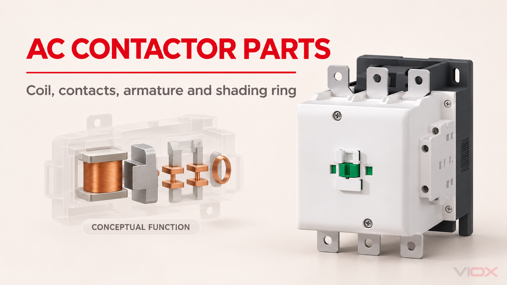
An AC contactor is an electrically operated switch for repeatedly controlling a power circuit. Its control coil does not carry the load current. Instead, the coil creates magnetic force, the armature transfers that force into mechanical movement, and the main contacts make or break the load path. A return mechanism opens the contacts when the coil is de-energized, while arc-control parts limit the stress created during switching.
The important detail is that an AC contactor is a coordinated mechanism, not just a coil and a set of terminals. Many models also include auxiliary contacts, arc barriers, removable coils, or other service features. The exact layout depends on the contactor family and rating, so a conceptual component map should not be treated as a model-specific dismantling or wiring drawing.
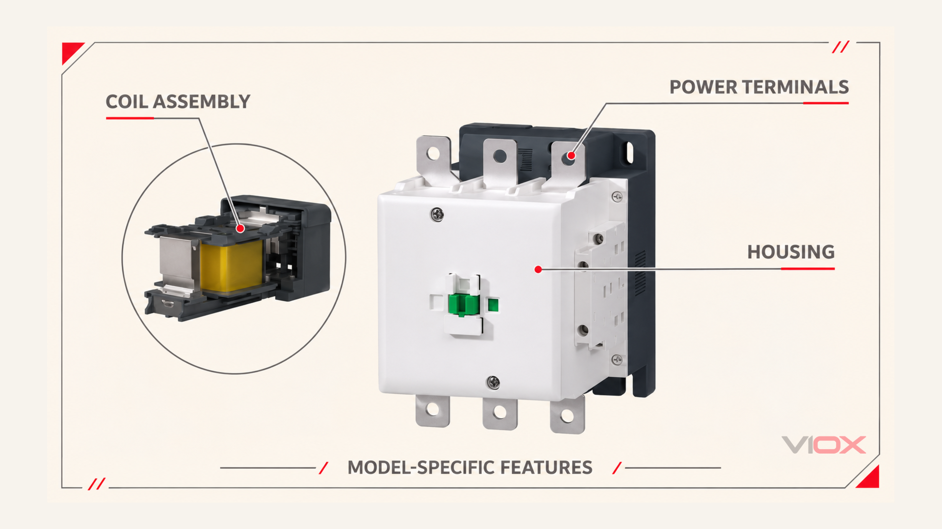
AC contactor parts at a glance
| Part or system | What it does | What to verify on a real model |
|---|---|---|
| Control coil | Creates the magnetic field that moves the armature | Coil voltage, frequency or DC designation, terminals, and the manufacturer’s control circuit data |
| Fixed magnetic core | Completes the magnetic path and supports the coil system | Construction, seating surfaces, and whether the design is for AC, DC, or electronically controlled operation |
| Movable armature | Moves when magnetic force overcomes the return force | Free movement, correct seating, contamination, and model-specific replacement parts |
| Main power contacts | Connect and disconnect the controlled load circuit | Pole count, utilization category, rated current, wear, pitting, and contact pressure specified by the manufacturer |
| Arc-control system | Guides, divides, cools, and helps extinguish arcs during switching | Arc barriers, chute parts, clearances, and the applicable contactor documentation |
| Return spring or mechanism | Opens the contacts when the coil releases | Release movement, spring condition, mechanical obstruction, and latch or interlock arrangement |
| Auxiliary contacts | Provide status, interlock, seal-in, or control feedback | Contact arrangement, rating, terminal numbering, and accessory compatibility |
| Housing and terminals | Insulate, support, and terminate the device | Creepage, clearance, terminal condition, enclosure fit, and tightening instructions |
These parts should be read as functional systems. A manufacturer may combine, move, or package them differently. The supplied VIOX structure reference, for example, shows a product platform with features such as a removable lower coil arrangement, a dust cover, auxiliary contacts, and arc-barrier geometry. Those features should be treated as characteristics of the shown platform or series, not as universal properties of every AC contactor.
How the mechanism operates
1. The control circuit energizes the coil
When the correct control voltage reaches the coil, it produces magnetic flux in the core and armature circuit. The control circuit therefore provides the command; it does not directly switch the motor, heater, compressor, or other load. The coil voltage and frequency must match the device marking and documentation. A coil that is physically similar but electrically different is not a safe replacement.
At pickup, the air gap is larger and the magnetic circuit needs more force to move the armature. Once the armature is seated, the magnetic circuit changes and the coil’s operating condition may be different. Some contactors use electronic or dual-coil control arrangements to manage pickup and holding power. Do not infer a particular coil architecture from the outside shape alone.
2. The armature closes the power contacts
The armature is the moving link between the magnetic system and the contact carrier. As it closes, it applies mechanical force to the movable contacts. The main contacts then connect the line and load terminals for the poles provided by that contactor.
The contactor’s current rating is not a universal statement that it can switch every load at that current. Selection depends on the load type, voltage, utilization category, duty cycle, starting conditions, and the manufacturer’s declared ratings. IEC 60947-4-1:2023 covers electromechanical contactors and motor-starters intended for distribution, motor, and other load circuits up to 1,000 V AC or 1,500 V DC; the applicable product data still determines whether a particular use is suitable. Read the IEC 60947-4-1 scope.
3. The arc-control system manages separation
When a contactor opens an energized inductive load, current does not necessarily stop at the instant the metal surfaces separate. An arc can form between the contacts. Arc barriers, runners, chambers, or chutes guide and stretch that arc so it can cool and extinguish under the conditions for which the contactor is rated.
This is load-switching control. It is not the same as a circuit breaker’s short-circuit protection function. A contactor should be coordinated with the required short-circuit protective device and assembly conditions. The presence of an arc chute does not mean the contactor alone can interrupt any prospective fault current.
4. The return mechanism opens the circuit
When the coil is de-energized, the magnetic force falls and the return spring moves the armature and contact carrier back to the open position. The release path must be free of dust, deformation, damaged parts, and incorrect accessories. A contactor that hums, chatters, sticks, or fails to release needs diagnosis rather than repeated manual forcing.
What is a shading coil or shading ring in a contactor?
A shading coil, also called a shading ring or short-circuit ring, is a conductive loop fitted around part of the magnetic pole face in many AC electromagnetic devices. It is not the main control coil and is not normally connected to the external control terminals.
The AC magnetic flux changes every cycle and passes through a zero-value point. Without a suitable phase-shifted component, the attractive force can fall enough for the armature to vibrate or chatter. The changing flux induces current in the shading ring. That induced current creates a secondary magnetic flux displaced in phase from the main flux, helping maintain attraction during the interval when the main flux is low.
The result is more stable AC magnetic operation. A damaged, loose, or missing shading ring can contribute to hum or chatter. The ring reduces force pulsation; it does not correct an undervoltage coil supply, contaminated pole faces, or mechanical damage. Closing-impact contact bounce is a related but separate dynamic effect, not something every shading ring eliminates. IEEE research on shading-coil design examines the relationship between ring parameters and contactor motion.
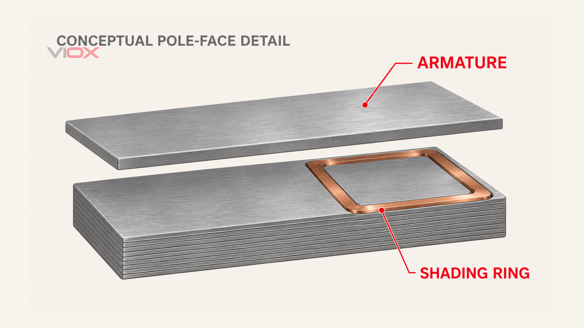
The effect is specific to the magnetic design. A DC coil does not have the same AC zero-crossing problem and normally does not use a shading ring for this purpose. Electronically controlled contactors may use a different internal arrangement. This is why the correct replacement must be identified from the model documentation rather than from a generic image.
How the supplied VIOX structure reference should be read
The supplied product structure image shows several design features that are useful when reviewing a contactor platform:
- Dual-coil control circuit: the image presents a pickup and holding arrangement intended to reduce holding power after the armature has seated. Treat the stated energy-saving performance as a product-specific claim that must be confirmed in the applicable datasheet.
- Bottom drawer-type coil: a removable or service-oriented coil arrangement can simplify maintenance on a compatible series. It does not mean coils from different families are interchangeable.
- Auxiliary contacts: normally open and normally closed contacts can provide status, interlocking, or seal-in functions. Their ratings and terminal numbers must be checked separately from the main contacts.
- Arc barriers: barriers can separate poles and support insulation or arc-control requirements. Their presence does not establish a short-circuit rating by itself.
- Dust cover and housing: enclosure features help protect internal mechanisms and maintain intended clearances, but the complete assembly still needs the manufacturer’s installation conditions.
These are visible product-platform features, not a universal internal cross-section. If a procurement team needs a replacement coil, auxiliary block, cover, or arc barrier, the request should include the exact series, frame, coil code, pole arrangement, and accessory code.
Contact materials: what they are designed to balance
Main contacts often use a contact material system selected for a balance of conductivity, resistance to welding, arc erosion, and expected load duty. Silver-based contact materials are common, but the exact composition and construction vary by application. A material name alone does not determine the contactor’s complete switching capability.
For replacement and specification work, prioritize the declared electrical ratings and utilization category over a generic claim that one silver alloy is always superior. The contact material, contact geometry, spring force, arc-control system, load waveform, and switching frequency work together. Do not apply a universal milliohm replacement threshold unless the manufacturer supplies a measurement method and limit for that model.
Separate the coil supply from the switched load
An AC-load contactor can have an AC coil, a DC coil, or an electronic control module accepting a declared supply range. The load rating does not identify the actuator construction. Shading rings and laminated cores relate to the magnetic actuator; arc-control requirements relate to the circuit being switched.
A DC control coil does not make the main contacts suitable for a DC load. Conversely, an AC load rating does not prove that the actuator contains a conventional AC shading ring. Check both sets of ratings independently. Laminations interrupt eddy-current paths in an alternating magnetic field; they do not justify a universal loss-reduction percentage or a claim that every DC design must use a solid core.
What to check before replacing an AC contactor
Use this short evidence checklist before ordering a replacement:
- Record the exact model and series, not only the visible current number.
- Match the coil voltage, frequency, or DC control specification.
- Confirm the number of main poles and the required load-side arrangement.
- Check the load type and utilization category, especially for motors, compressors, capacitors, heaters, and frequent jogging.
- Verify the main-contact ratings at the actual system voltage and duty.
- Confirm auxiliary contact arrangement, terminal numbering, interlocks, and accessory compatibility.
- Check mounting dimensions, terminal clearances, conductor size, and enclosure space.
- Confirm the upstream short-circuit protective device and coordination requirements.
- If the symptom is hum or chatter, have a qualified person distinguish control-supply problems from mechanical or magnetic-circuit defects. De-energize, isolate all power and control sources, and verify absence of voltage before opening or handling the mechanism. Energized measurements require appropriate competence and procedures; do not remove a shading ring or hold a contactor closed by hand.
For product-family information, see the VIOX AC contactor range. For the terminology and operating boundary, see what a contactor is. If the device is part of a motor starter, keep the overload relay and short-circuit protective device in the review; a contactor alone is not a complete motor-protection system. The contactor versus motor starter guide explains that boundary.
Final takeaway
The coil creates magnetic force, the armature transfers it, the main contacts switch the load, the arc-control system manages separation, and the return mechanism opens the circuit when the command is removed. Auxiliary contacts extend the contactor into control logic. In many AC magnetic systems, the shading ring supplies phase-shifted flux near the main AC flux zero and prevents the humming and chatter that would otherwise occur.
The supplied VIOX structure reference adds useful model-platform clues such as a drawer-type coil, auxiliary contacts, dust protection, and arc barriers. Use those clues together with the exact datasheet and accessory list. Do not treat a conceptual component map or a similar-looking contactor as proof that a replacement has the same coil, internal construction, ratings, or short-circuit coordination.