Product Overview
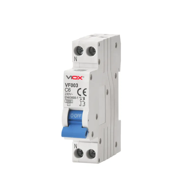
The VIOX VF003 is a 1P+N miniature circuit breaker for overload and short-circuit protection in low-voltage final distribution circuits. It combines thermal overload protection, magnetic short-circuit tripping, and manual circuit isolation in a compact DIN-rail device.
Current product data covers rated currents from 2A to 32A, 120V and 230/400V to 240/415V applications at 50/60Hz, and breaking capacities of 3kA, 4.5kA, or 6kA. The VF003 is intended for residential, commercial, and selected industrial control or distribution circuits when its rating, trip curve, conductor capacity, and breaking capacity are correctly coordinated with the installation.
Key Features
- Thermal-magnetic overload and short-circuit protection
- 1P+N configuration for final distribution circuits
- Rated current options from 2A to 32A
- Breaking capacity options of 3kA, 4.5kA, and 6kA
- Energy limiting class 3
- Contact-position indication
- 35mm DIN-rail mounting with fast clip device
- Top or bottom connection and compatible auxiliary accessories
Technical Specifications
Electrical Data
| Parameter | Specification |
|---|---|
| Model | VF003 |
| Poles | 1P+N |
| Rated current (In) | 2A, 6A, 10A, 16A, 20A, 25A, 32A |
| Rated voltage (Ue) | 120V; 230/400V to 240/415V AC |
| Rated frequency | 50/60Hz |
| Rated insulation voltage (Ui) | 500V |
| Rated impulse withstand voltage (Uimp) | 4kV |
| Rated breaking capacity | 3kA, 4.5kA, 6kA |
| Energy limiting class | 3 |
| Trip curve shown in current technical table | B, C |
| Power-frequency dielectric test | 2kV for 1 minute |
| Standard | IEC/EN 60898-1 |
Mechanical and Environmental Data
| Parameter | Specification |
|---|---|
| Electrical life | 10,000 operations |
| Mechanical life | 20,000 operations |
| Contact-position indicator | Yes |
| Protection degree | IP20 |
| Reference temperature for thermal setting | 30°C |
| Ambient temperature | -5°C to 40°C; daily average not above 35°C |
| Storage temperature | -25°C to 70°C |
| Pollution degree | 2 |
Installation Data
| Parameter | Specification |
|---|---|
| Terminal connection | Cable, U-type busbar, or pin-type busbar |
| Cable terminal capacity | Up to 25mm² / 18–4 AWG |
| Busbar terminal capacity | Up to 10mm² / 18–8 AWG |
| Tightening torque | 2.5N·m / 22in-lb |
| Mounting | 35mm DIN rail to EN 60715, fast clip device |
| Connection direction | Top or bottom |
Selection Guide
Select the VF003 configuration by coordinating the protective device with the circuit load, conductor capacity, installation conditions, and prospective short-circuit current. Final selection should follow the applicable installation standard and project design.
Rated Current
Choose a rated current from 2A to 32A that protects the installed conductor while supporting the design load and applicable correction factors.
Trip Curve
The current technical table lists B and C curves. Use the curve that matches the expected inrush characteristics and confirm availability for the ordered version.
Breaking Capacity
Select 3kA, 4.5kA, or 6kA only after confirming that the device rating exceeds the prospective short-circuit current at the installation point.
Dimensions
The verified overall and mounting drawing for VF003 will be added here. Dimensions are not borrowed from another MCB model.
Applications
Typical low-voltage final-distribution and control environments where the VF003 rating and protection characteristics may be coordinated with the circuit design.
- Residential lighting, socket-outlet, and household final circuits
- Commercial lighting, office equipment, and building distribution circuits
- Industrial control and auxiliary circuits with suitable inrush characteristics
Installation and Commissioning
Mounting
Install vertically on a standard 35mm DIN rail using the integrated fast clip. Maintain the enclosure clearances required by the installation design.
Wiring
Use a conductor and terminal format within the stated capacity. Tighten terminals to 2.5N·m and verify that each conductor is fully secured before energizing.
Inspection
Before commissioning, confirm mounting, conductor security, manual operation, circuit isolation, and protective-device coordination using appropriate test procedures.
Accessories and System Integration
Current VF003 product information lists compatibility with the following auxiliary functions. Confirm the matching accessory model and wiring arrangement before ordering.
- Auxiliary contact for remote status indication
- Shunt release for remote tripping
- Undervoltage release for voltage-dependent disconnection
- Alarm contact for trip indication
Compliance and Documentation
The current VF003 technical data identifies IEC/EN 60898-1 as the applicable miniature circuit breaker standard.
Existing product material also references NF, UKCA, and CE. Certification and declaration documents should be confirmed for the selected version and destination market before they are used in a project submittal.
FAQ
What pole configuration does the VF003 use?
The current VF003 product data identifies the device as a 1P+N miniature circuit breaker.
Which rated currents are listed for VF003?
The listed rated-current options are 2A, 6A, 10A, 16A, 20A, 25A, and 32A.
Which breaking capacities are available?
Current product data lists 3kA, 4.5kA, and 6kA. The selected capacity must exceed the prospective short-circuit current at the installation point.
Which trip curves are shown in the technical table?
The current technical table lists B and C curves. Confirm the required curve and its availability when ordering.
Can the VF003 be supplied from the top or bottom?
The current installation data allows connection from the top or bottom, subject to the project wiring design.
Which auxiliary functions are referenced?
The current product material references auxiliary contact, shunt release, undervoltage release, and alarm contact compatibility.
Which compliance documents are available?
IEC/EN 60898-1 is identified in the technical data. NF, UKCA, CE, and destination-specific documentation should be confirmed for the selected version.