Pada halaman ini
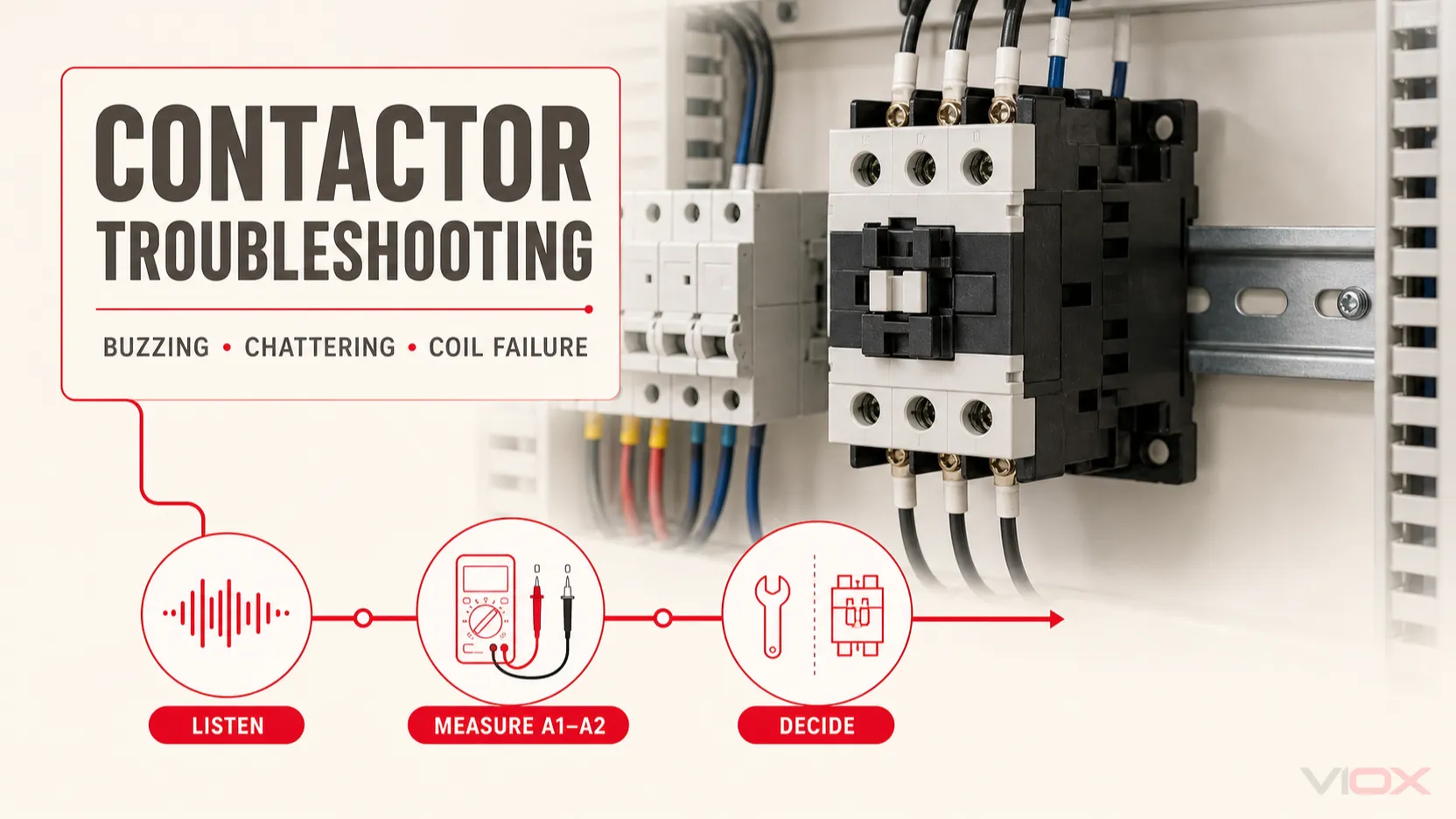
Kontaktor yang berdengung atau bergetar biasanya disebabkan oleh voltan gegelung yang tidak stabil atau tidak mencukupi, sambungan litar kawalan yang lemah, gegelung yang tidak betul, kedudukan angker yang tidak lengkap, permukaan magnet yang tercemar, kekangan mekanikal, atau gelang teduhan (shading ring) yang rosak pada kontaktor AC konvensional. Kerosakan ini tidak sama, jadi pembaikan terpantas bermula dengan mengenal pasti bunyi tersebut dan memeriksa voltan gegelung pada kontaktor—bukan hanya pada punca kuasa.
Matikan tenaga, kunci keluar (lock out), dan pastikan tiada voltan sebelum membuka kepungan atau menyentuh kontaktor. Pengukuran bertenaga dan diagnosis kerosakan hanya boleh dilakukan oleh kakitangan elektrik yang berkelayakan dengan menggunakan PPE dan peralatan ujian yang sesuai.
Pengambilan Utama
- Bunyi dengung yang perlahan dan stabil mungkin normal bagi sesetengah kontaktor AC konvensional. Bunyi baharu yang kuat, berdetar, atau berselang-seli perlu disiasat.
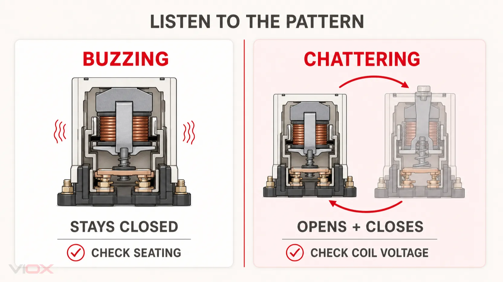
- Berdengung biasanya bermaksud kontaktor kekal tertutup tetapi sistem magnet sedang bergetar. Bergetar bermaksud angker berulang kali tertarik masuk dan terlepas keluar.
- Ukur voltan terus merentasi terminal gegelung A1 dan A2 semasa kontaktor diarahkan untuk tertutup, kemudian bandingkan dengan papan nama gegelung dan had operasi pengilang.
- Voltan kawalan yang rendah atau tidak stabil boleh menghalang penyentuh (contactor) daripada tertutup rapat, yang meningkatkan arka sesentuh, haba, haus mekanikal, dan risiko sesentuh terlekat (welded contacts).
- Gantikan penyentuh apabila ia mempunyai sesentuh yang terlekat, gelang teduhan (shading ring) yang patah, pemasangan magnet yang berubah bentuk, penebat yang rosak akibat haba, atau perumah yang retak atau cair.
- Jangan kikir atau gosok permukaan sesentuh atau permukaan magnet kecuali pengeluar membenarkan prosedur tersebut secara khusus untuk model yang tepat.
Jadual Penyelesaian Masalah Penyentuh Pantas
| simptom | Punca yang mungkin | Pemeriksaan awal | Tindakan yang disyorkan |
|---|---|---|---|
| Bunyi dengung yang kuat dan berterusan, tetapi penyentuh kekal tertutup | Permukaan kutub yang kotor atau berkarat, kedudukan angker (armature) yang tidak lengkap, gegelung yang tidak betul, gelang teduhan yang rosak, pemasangan yang longgar | Bandingkan bunyi dengan operasi biasa; periksa pengenalpastian gegelung dan kedudukan angker | Asingkan bekalan kuasa, bersihkan hanya jika dibenarkan, betulkan isu gegelung atau pemasangan, atau gantikan bahagian/kontaktor yang rosak |
| Tarikan masuk dan lepasan yang pantas | Voltan gegelung rendah atau tidak stabil, sentuhan kawalan lemah, terminal longgar, pengubah kawalan bersaiz kecil, penderia atau geganti yang bergetar | Ukur voltan A1–A2 semasa pengambilan (pickup) dan semasa beban bermula | Baiki kejatuhan voltan atau kerosakan litar kawalan sebelum menggantikan kontaktor |
| Gegelung bertenaga tetapi kontaktor tidak mahu menarik masuk | Voltan gegelung salah, voltan tidak mencukupi, halangan mekanikal, ikatan, gegelung atau pemasangan magnet yang rosak | Sahkan kadaran gegelung, voltan arahan, dan pergerakan bebas selepas pengasingan | Betulkan bekalan atau halangan; gantikan gegelung yang rosak hanya jika ia merupakan alat ganti yang diluluskan oleh pengilang |
| Tiada tindak balas apabila diarahkan | Litar kawalan terbuka, fius kawalan terbakar, peranti output rosak, wayar longgar, gegelung terbuka | Kesan arahan kawalan dan periksa voltan pada A1–A2 | Pulihkan litar kawalan atau gantikan komponen yang rosak |
| Penyentuh (contactor) tidak mahu terlepas | Sesentuh kuasa terkimpal, ikatan mekanikal, voltan kawalan baki, peranti penindas yang tidak betul | Pastikan gegelung tidak bertenaga; uji untuk voltan baki | Betulkan isu kawalan; gantikan penyentuh (contactor) yang mempunyai sesentuh terlekat atau kerosakan mekanikal |
| Haba berlebihan, perubahan warna, atau bau terbakar | Tamatan longgar, beban lampau, keadaan sesentuh yang lemah, kitaran berlebihan, kategori penggunaan yang salah, bunyi ketukan berterusan | Asingkan bekalan dengan segera; periksa tamatan, keadaan pengalir, arus beban, dan kadaran penyentuh | Betulkan punca masalah dan gantikan peralatan yang rosak akibat haba |
Keselamatan Sebelum Melakukan Penyelesaian Masalah
Penyentuh boleh mengandungi voltan talian yang berbahaya walaupun litar gegelungnya dimatikan. Sebelum pemeriksaan fizikal:
- Patuhi prosedur keselamatan elektrik tapak dan kenal pasti setiap punca kuasa dan kawalan.
- Hentikan peralatan yang dikawal dan lakukan prosedur kunci keluar/tanda keluar (lockout/tagout).
- Sahkan ketiadaan voltan dengan penguji yang sesuai menggunakan kaedah hidup-mati-hidup (live-dead-live) yang diperlukan.
- Nyahcas tenaga yang tersimpan dan pastikan jentera yang bergerak berada dalam keadaan selamat jika berkenaan.
- Jangan sekali-kali memintas kunci saling (interlock) atau memegang angker (armature) dalam keadaan tertutup dengan tangan atau menggunakan alat.
Beberapa pemeriksaan dalam panduan ini memerlukan voltan diukur semasa gegelung diaktifkan. Hanya kakitangan berkelayakan sahaja yang dibenarkan melakukan ujian bertenaga, dan hanya apabila ia wajar dilakukan berdasarkan penilaian risiko dan peraturan tempatan.
Adakah Penyentuh (Contactor) mengeluarkan bunyi berdengung, berdesir, atau bergetar?
Corak bunyi tersebut dapat mengecilkan skop kerosakan sebelum penutup dibuka.
Bunyi dengung biasa atau perlahan
Sesetengah penyentuh (contactor) AC konvensional menghasilkan bunyi dengung yang rendah dan stabil akibat medan magnet ulang-alik. Jika bunyi tersebut sentiasa ada, penyentuh tertutup dengan kemas, suhu adalah normal bagi model tersebut, serta tiada getaran atau bau, ia mungkin bukan menunjukkan kerosakan.
Jangan bergantung pada had desibel universal. Bunyi yang boleh diterima bergantung pada reka bentuk penyentuh, saiz, pemasangan, resonans kepungan, kualiti voltan, dan spesifikasi pengilang.
Bunyi dengung yang kuat
Penyentuh yang berdengung kuat tetapi kekal tertutup biasanya menunjukkan getaran dalam sistem magnet. Punca biasa termasuk permukaan kutub yang kotor atau berubah bentuk, angker yang tidak dapat duduk dengan sempurna, gelang teduhan (shading ring) yang rosak, pemilihan gegelung yang tidak tepat, atau kepungan atau permukaan pemasangan yang menguatkan getaran.
Bergetar
Penyentuh yang bergetar (chattering) akan membuka dan menutup secara berulang. Ia sering kedengaran seperti bunyi klik atau ketukan pantas dan bukannya dengung yang berterusan. Anggap ia sebagai kerosakan segera: gangguan berulang boleh meningkatkan arka dan kehausan pada sesentuh utama sambil memberi tekanan pada gegelung dan pemasangan mekanikal.
Apakah punca penyentuh bergetar atau berdengung?
Voltan Gegelung Rendah atau Tidak Stabil
Gegelung mungkin menerima voltan yang mencukupi untuk mula menarik angker tetapi tidak cukup untuk memegangnya dengan kukuh. Apabila angker terlepas, keadaan litar berubah dan penyentuh (contactor) cuba semula, menyebabkan bunyi bergetar (chatter).
Voltan pada transformer atau panel kawalan mungkin kelihatan normal manakala voltan pada A1 dan A2 merosot semasa proses penarikan (pickup). Pengalir yang panjang, terminal yang longgar, transformer kawalan yang lemah, sesentuh berintangan tinggi, atau beban permulaan serentak boleh menyumbang kepada masalah ini. Bandingkan nilai yang diukur dengan tanda gegelung yang tepat dan julat operasi yang diterbitkan oleh pengilang; jangan gunakan satu ambang peratusan untuk setiap reka bentuk penyentuh dan gegelung elektronik.
Sesentuh yang Lemah dalam Litar Kawalan
Butang tekan yang haus, output PLC yang tidak stabil, suis had yang melantun, suis tekanan yang rosak, terminal yang longgar, atau geganti perantara yang rosak boleh mengganggu bekalan gegelung secara berulang kali. Jika penyentuh bergetar hanya apabila peranti input tertentu beroperasi, uji bahagian rantaian arahan tersebut dan bukannya menganggap penyentuh itu rosak.
Kedudukan Angker yang Tidak Lengkap
Habuk, karat, kakisan, bahan asing, gangguan mekanikal, atau permukaan magnet yang berubah bentuk boleh meninggalkan jurang udara kecil apabila penyentuh tertutup. Jurang yang lebih besar meningkatkan getaran magnet dan boleh menyebabkan gegelung menjadi lebih panas.
Selepas pengasingan, periksa pemasangan bergerak untuk pergerakan bebas dan periksa permukaan magnet yang boleh diakses mengikut arahan pengilang. Panduan ABB untuk penyentuh konvensional mengesyorkan pembersihan permukaan kutub magnet yang kotor dengan kain yang lembut dan kering. Bahan pelelas boleh mengubah permukaan pertemuan dan memburukkan lagi masalah.
4. Gelang Shading yang Rosak atau Longgar
Gelang shading—juga dipanggil gegelung shading—merupakan sebahagian daripada sistem magnet dalam kebanyakan penyentuh (contactor) AC konvensional. Ia membantu mengekalkan daya pegangan semasa bentuk gelombang AC melintasi sifar. Jika ia pecah atau menjadi longgar, penyentuh mungkin mengeluarkan bunyi dengung yang kuat atau bergetar walaupun voltan kawalan adalah betul.
Gelang shading yang rosak tidak boleh dibaiki di lapangan untuk prosedur penyelesaian masalah am. Gantikan keseluruhan penyentuh atau pemasangan magnet yang diluluskan oleh pengilang, bergantung pada arahan produk. Untuk penjelasan peringkat komponen, lihat Di Dalam Sebuah Kontaktor AC: Komponen dan Logik Reka Bentuk.
5. Gegelung atau Bekalan yang Tidak Betul
Periksa tanda penuh pada gegelung, termasuk voltan terkadar, jenis AC atau DC, frekuensi jika berkenaan, dan sebarang penetapan gegelung elektronik. Badan penyentuh mungkin menerima beberapa pilihan gegelung, jadi keluarga model sahaja tidak mengesahkan bahawa gegelung yang dipasang adalah betul.
Gegelung AC yang dibekalkan secara tidak betul, gegelung DC pada sumber yang salah, atau gegelung gantian dengan julat kawalan yang berbeza boleh menyebabkan kegagalan, pemanasan melampau, atau kegagalan untuk berfungsi dengan stabil.
6. Resonans Pemasangan atau Enklosur
Penyentuh yang berada dalam keadaan mekanikal yang baik boleh mengeluarkan bunyi yang jauh lebih kuat apabila rel DIN yang longgar, panel nipis, penutup enklosur, atau komponen berdekatan mengalami resonans. Periksa kedudukan pemasangan dan kaedah pengikat yang ditetapkan. Resonans hanya perlu dipertimbangkan selepas mengesahkan bahawa angker tertutup sepenuhnya dan bekalan elektrik adalah betul.
Prosedur Penyelesaian Masalah Kontaktor Langkah demi Langkah
Langkah 1: Rekodkan Simptom Operasi
Sebelum penutupan, catatkan sama ada kontaktor:
- berdengung secara berterusan atau hanya semasa proses penarikan (pickup);
- bergetar (chatter) hanya apabila motor atau beban bermula;
- tertutup sepenuhnya tetapi mengeluarkan bunyi bising;
- gagal untuk menarik (pull in) sama sekali;
- terlepas apabila arahan dialihkan;
- menunjukkan haba, bau, perubahan warna, atau arka yang boleh dilihat.
Video pendek atau trend voltan kawalan boleh membantu menangkap masalah yang berlaku secara berkala, dengan syarat rakaman tidak mendedahkan kakitangan kepada bahagian hidup.
Langkah 2: Kenal pasti Penyentuh (Contactor) dan Gegelung yang Tepat
Selepas pengasingan, rekodkan pengeluar, model, kod gegelung, voltan gegelung terkadar, jenis bekalan, frekuensi, kategori penggunaan, dan kadaran beban. Sahkan bahawa penyentuh yang dipasang adalah sesuai untuk aplikasi dan tugas tersebut. Penukaran motor, penukaran kapasitor, beban pemanasan, dan pembalikan yang kerap tidak memberikan tekanan yang sama.
Untuk seni bina kawalan motor dan perlindungan beban lampau, lihat Penyentuh (Contactor) lwn Pemula Motor (Motor Starter): Apakah Perbezaannya?.
Langkah 3: Periksa Arahan Kawalan dan Voltan Gegelung
Kakitangan berkelayakan boleh mengukur voltan secara terus merentasi A1 dan A2:
- Tanpa arahan tutup, pastikan gegelung tidak menerima voltan baki yang tidak disengajakan.
- Berikan arahan tutup dan perhatikan voltan semasa pengambilan awal.
- Teruskan pemerhatian semasa beban yang disambungkan bermula, di mana pengubah kawalan atau bekalan mungkin mengalami penurunan voltan.
- Bandingkan keputusan dengan label gegelung dan helaian data pengeluar.
Jika voltan rendah atau tidak stabil, periksa bahagian hulu melalui fius, terminal, butang tekan, suis, output PLC atau geganti, pendawaian, dan sumber kuasa kawalan. Betulkan masalah tersebut sebelum memasang penyentuh (contactor) baharu.
Langkah 4: Periksa Laluan Mekanikal
Dengan semua tenaga diputuskan, periksa pergerakan bebas, bahan asing, kakisan, spring yang rosak, angker yang terherot, dan tanda-tanda bahawa permukaan magnet tidak duduk dengan sempurna. Ikuti arahan pembersihan dan servis pengeluar. Jangan melincirkan permukaan magnet atau menggunakan pelarut am.
Langkah 5: Menilai Gegelung
Bukti visual seperti penebat retak, lebur, perubahan warna, atau bau terbakar boleh menunjukkan kerosakan gegelung. Pemeriksaan rintangan atau keterusan mungkin dapat mengenal pasti belitan terputus, tetapi tiada julat rintangan universal untuk semua gegelung penyentuh. Bandingkan bacaan dengan data pengilang atau gegelung yang sama yang telah disahkan di bawah keadaan suhu yang serupa.
Perlu diingat juga bahawa gegelung boleh melepasi pemeriksaan rintangan statik namun masih gagal berfungsi disebabkan oleh kerosakan penebat, sambungan terputus-putus, atau bekalan yang tidak betul.
Langkah 6: Memeriksa Litar Kuasa
Periksa terminal yang longgar atau rosak akibat haba, perubahan warna pengalir, kehausan sesentuh yang tidak normal, dan bukti kimpalan. Semak arus beban dan tugas operasi berbanding kadaran peranti serta kategori aplikasi. Gunakan nilai tork terminal dan had pemeriksaan yang diterbitkan oleh pengilang—nilai tork atau kehausan sesentuh generik tidak boleh dipercayai merentasi keluarga produk.
Kegagalan Gegelung Penyentuh: Baiki atau Ganti?
Sesetengah penyentuh mempunyai gegelung yang boleh diganti; reka bentuk yang padat mungkin tidak membenarkannya. Penggantian hanya sesuai dilakukan apabila disokong oleh pengilang dan pemasangan magnet, sesentuh, perumah, serta mekanisme masih dalam keadaan boleh diservis.
| Penemuan | Keputusan tipikal |
|---|---|
| Wayar kawalan luaran longgar atau suis hulu yang rosak | Baiki litar kawalan, kemudian sahkan operasi |
| Habuk pada permukaan magnet yang boleh dicapai tanpa kerosakan | Bersihkan hanya dengan kaedah yang diluluskan dan uji semula |
| Gegelung boleh ganti disahkan terbuka atau rosak | Pasang gegelung yang diluluskan dengan tepat dan siasat punca kegagalannya |
| Gelang teduhan (shading ring) patah atau permukaan magnet berubah bentuk | Gantikan penyentuh (contactor) atau pemasangan magnet yang diluluskan |
| Sesentuh utama yang terkimpal | Gantikan penyentuh dan betulkan punca elektrik |
| Perumah yang retak, cair, berkarbon, atau berubah warna dengan teruk | Gantikan penyentuh |
| Terlalu panas atau bunyi bergetar (chatter) yang berulang selepas pembetulan bekalan | Gantikan dan nilai semula pemilihan, tugas, dan reka bentuk kawalan |
Jangan anggap penyentuh baharu sebagai pembaikan lengkap jika punca masalah adalah voltan kawalan rendah, kitaran berlebihan, kategori penggunaan yang tidak sesuai, tamatan yang longgar, pencemaran, atau peranti arahan yang tidak stabil. Penggantian tersebut boleh gagal dengan cara yang sama.
Cara Mencegah Kegagalan Berulang
- Pilih gegelung untuk bekalan kawalan sebenar, termasuk frekuensi dan julat yang dibenarkan oleh pengilang.
- Tentukan saiz transformer kawalan dan pendawaian untuk permintaan pengambilan (pickup demand) dan beban serentak.
- Gunakan tamatan yang selamat dan nilai tork yang ditetapkan oleh pengilang.
- Lindungi kepungan daripada habuk konduktif, kelembapan, kakisan, dan pemeluwapan.
- Padankan kategori penggunaan dan tugas penyentuh (contactor) dengan beban, bukannya memilih berdasarkan arus sahaja.
- Siasat perubahan pada bunyi, masa pengambilan, suhu, atau keadaan sesentuh sebelum ia menjadi kegagalan.
- Tetapkan selang pemeriksaan berdasarkan panduan pengilang, kekerapan operasi, persekitaran, dan kesan kegagalan, bukannya menggunakan jadual bulanan atau tahunan yang universal.
Sering Bertanya Soalan-Soalan
Mengapakah penyentuh (contactor) saya mengeluarkan bunyi berdengung yang kuat tetapi masih berfungsi?
Angker mungkin tertutup tetapi tidak duduk dengan betul disebabkan oleh pencemaran, ubah bentuk, gelang teduhan (shading ring) yang rosak, gegelung yang tidak betul, atau kehausan sistem magnet. Resonans pemasangan boleh menguatkan bunyi tersebut. Sahkan voltan gegelung dan periksa pemasangan magnet selepas pengasingan yang selamat.
Bolehkah voltan rendah menyebabkan penyentuh bergetar (chatter)?
Ya. Voltan yang tidak mencukupi atau tidak stabil pada A1 dan A2 boleh menyebabkan proses tarik dan lepas yang berulang. Ukur pada gegelung semasa arahan tutup diberikan dan semasa beban bermula, kemudian bandingkan hasilnya dengan had operasi pengeluar yang tepat.
Bolehkah saya membersihkan penyentuh yang bising?
Hanya jika pengeluar membenarkan pembersihan untuk model tersebut. Permukaan magnet yang kotor dan boleh dicapai kadangkala boleh dibersihkan dengan kain lembut dan kering selepas pengasingan. Jangan kikir, gosok dengan kertas pasir, melincirkan, atau menyembur penyentuh melainkan arahan produk membenarkannya secara jelas.
Bagaimanakah cara saya menguji gegelung penyentuh?
Sahkan pengenalan gegelung, periksa sama ada voltan arahan yang betul sampai ke A1 dan A2, periksa kerosakan haba, dan uji keselanjaran atau rintangan selepas pengasingan. Bandingkan rintangan hanya dengan data pengeluar atau gegelung yang sama dan diketahui dalam keadaan baik; julat rintangan umum adalah tidak boleh dipercayai.
Apakah yang akan berlaku jika gelang teduhan (shading ring) penyentuh (contactor) rosak?
Pada penyentuh AC konvensional, gelang teduhan yang rosak boleh menyebabkan bunyi dengung yang kuat atau getaran (chatter) kerana daya pegangan magnet menjadi kurang stabil di sekitar titik lintasan sifar AC. Ikuti arahan penggantian pengeluar; penggantian keseluruhan penyentuh biasanya diperlukan.
Adakah getaran penyentuh (contactor chattering) berbahaya?
Ia boleh menjadi berbahaya kerana pembukaan dan penutupan yang berulang meningkatkan arka, haba, kehausan sesentuh, dan tekanan mekanikal. Asingkan peralatan jika terdapat bau terbakar, perubahan warna, arka yang kelihatan, kegagalan untuk kekal tertutup, atau tingkah laku beban yang tidak normal.
Bilakah penyentuh yang bising perlu diganti?
Gantikannya apabila pemeriksaan mendapati sesentuh telah melekat atau rosak teruk, gelang teduhan patah, bahagian magnet berubah bentuk, mekanisme rosak, penebat gagal, atau perumah retak atau cair. Jika penyentuh hanya menguatkan getaran kepungan, betulkan isu pemasangan hanya selepas kerosakan elektrik dan magnet diketepikan.
Kesimpulan
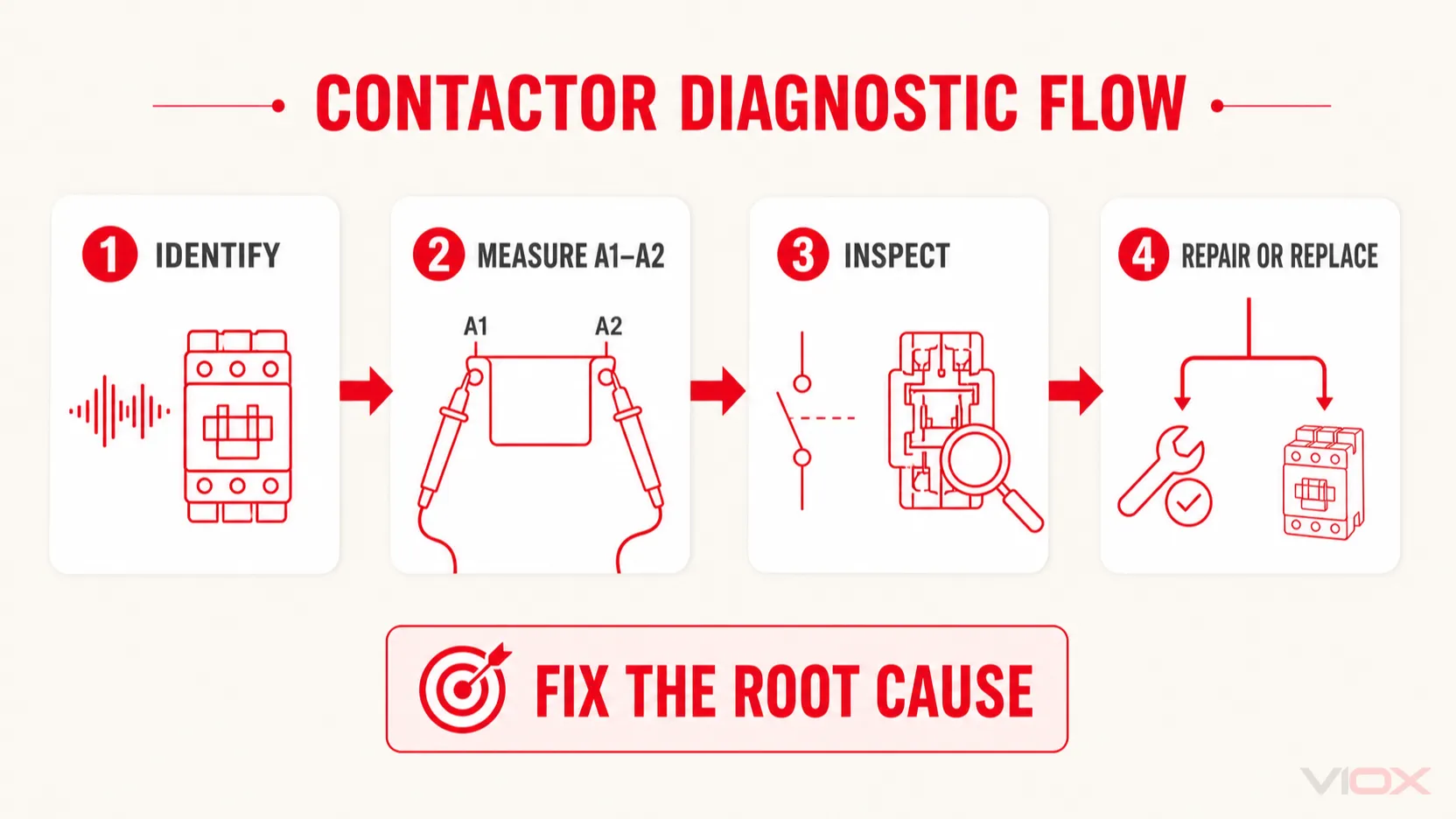
Penyelesaian masalah penyentuh yang berkesan mengikut urutan mudah: kenal pasti sama ada simptomnya adalah dengung, bunyi bising, atau getaran; sahkan gegelung yang tepat; ukur voltan pada A1 dan A2 di bawah keadaan operasi sebenar; periksa litar kawalan; dan kemudian periksa angker, permukaan magnet, gelang teduhan, dan sesentuh kuasa selepas pengasingan.
Jika bekalan dan arahan kawalan stabil tetapi penyentuh masih bergetar atau berdengung dengan kuat, kerosakan pada pemasangan magnet berkemungkinan besar berlaku. Gantikan peralatan yang rosak akibat haba, melekat, berubah bentuk, atau rosak secara struktur dan bukannya cuba melakukan pembaikan secara improvisasi. VIOX boleh membantu OEM dan pembina panel menilai pemilihan penyentuh, pilihan gegelung, kategori penggunaan, dan keperluan litar kawalan untuk aplikasi baharu.