 Guide: 10In vs 12In for Motor & Distribution Protection")
Direct Answer
For MCCB instantaneous trip settings, use 10In for distribution loads (lighting, receptacles, mixed circuits) and 12In for motor loads with direct-on-line starting. The instantaneous trip multiplier determines the current threshold at which your breaker trips immediately without delay. Setting it too low causes nuisance tripping during motor startup; setting it too high compromises short-circuit protection and creates safety hazards. The correct multiplier must exceed the peak inrush current by at least 20% while remaining low enough to clear dangerous faults within code-mandated timeframes.
Key Takeaways
Critical Selection Rules:
- Distribution circuits (lighting, receptacles): 10In instantaneous setting
- Direct-start motors (DOL): 12In instantaneous setting to ride through 7× FLA inrush
- Mixed loads: Match setting to primary load characteristic
- Always verify: Ii setting > 1.2× peak inrush current
- MCCBs ≠ MCBs: MCCBs use multiplier settings (10In, 12In), not curve types (B, C, D)
Common Mistakes to Avoid:
- Confusing MCCB instantaneous settings with MCB trip curves
- Ignoring ambient temperature derating requirements
- Oversizing multiplier “to be safe” (degrades protection)
- Using 10In for high-efficiency motors (requires 12In minimum)
Understanding MCCB Instantaneous Trip Settings
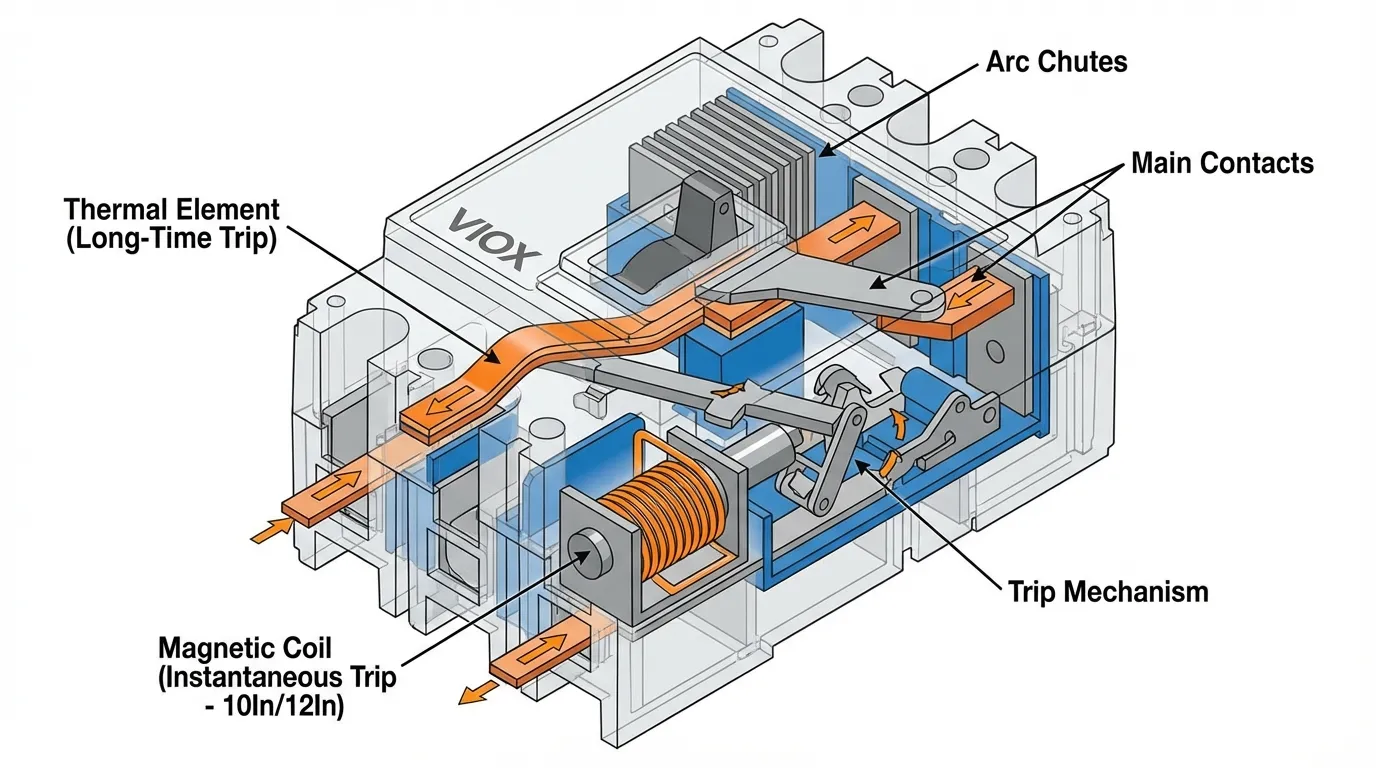
The instantaneous trip function in a molded case circuit breaker represents the magnetic element that responds to severe overcurrent without intentional delay. Unlike the thermal element that handles gradual overloads through an inverse time-current relationship, the instantaneous element acts within milliseconds when current exceeds the preset threshold. This threshold is expressed as a multiplier of the breaker’s rated current (In), typically ranging from 5In to 15In depending on application requirements.
When you see “10In” marked on an MCCB or in its settings, this means the magnetic trip will activate when current reaches ten times the breaker’s ampere rating. For a 100A breaker set at 10In, instantaneous tripping occurs at approximately 1,000A. The ±20% tolerance inherent in most thermal-magnetic trip units means the actual trip point falls between 800A and 1,200A. Understanding this tolerance band proves critical when coordinating protection devices or sizing for specific inrush currents.
The instantaneous setting serves two competing objectives. First, it must remain high enough to avoid nuisance tripping during normal transient events like motor starting, transformer energization, or capacitor bank switching. Second, it must stay low enough to provide rapid fault clearing before conductors, bus bars, or connected equipment suffer thermal or mechanical damage from short-circuit forces. Achieving this balance requires understanding the specific load characteristics and system fault levels at the installation point.
10In vs 12In: Technical Comparison
| Parameter | 10In Setting | 12In Setting |
|---|---|---|
| Primary Application | Distribution circuits, lighting, receptacles | Motor circuits with direct-on-line starting |
| Trip Threshold (100A breaker) | 1,000A (±20%) | 1,200A (±20%) |
| Maximum Inrush Tolerance | ~7× rated current | ~10× rated current |
| Typical Load Types | Resistive, small electronic loads, LED lighting | Induction motors, pumps, compressors, fans |
| Coordination Benefit | Faster fault clearing, better selectivity | Rides through motor LRA without tripping |
| NEC Compliance | Meets 240.6 requirements | Aligns with 430.52 motor protection |
| Nuisance Trip Risk | Low for resistive loads | Minimal for standard motors |
| Short-Circuit Response | 0.01-0.02 seconds | 0.01-0.02 seconds |
| Ambient Derating Impact | Must consider for continuous rating | Critical for high-temperature installations |
The fundamental difference between 10In and 12In settings lies in their accommodation of inrush current magnitude. Standard three-phase induction motors exhibit locked rotor current between 6 to 8 times full load amperes, with the asymmetrical peak reaching 1.4 to 1.7 times the symmetrical RMS value during the first half-cycle. A 37kW motor drawing 70A at full load produces approximately 490A symmetrical inrush, with asymmetrical peaks approaching 700-800A. A 10In setting on a 100A breaker (1,000A threshold) provides insufficient margin, while 12In (1,200A threshold) offers reliable operation.
Modern high-efficiency motors complicate this calculation further. Design improvements that reduce copper losses and improve power factor have simultaneously increased starting current multipliers. Where older motors might start at 6× FLA, contemporary premium-efficiency designs often reach 7-8× FLA. The NEC recognizes this reality in Article 430.52, permitting instantaneous trip settings up to 1,100% of motor FLA for inverse-time breakers protecting high-efficiency motors, compared to 800% for standard designs. This regulatory acknowledgment validates the practical need for 12In settings in modern motor applications.
Distribution circuits present a contrasting scenario. Lighting loads, particularly LED fixtures, exhibit minimal inrush—typically 1.5-2× steady-state current for less than one millisecond. Receptacle circuits serving computers, printers, and office equipment show similar behavior. Even accounting for simultaneous switching of multiple loads, the aggregate inrush rarely exceeds 5× the circuit’s continuous rating. A 10In setting provides ample margin while maintaining responsive short-circuit protection. Using 12In in these applications unnecessarily degrades protection coordination and extends fault-clearing time.
Three Real-World Application Cases
Case 1: Workshop Lighting Circuit (Pure Resistive Load)
System Parameters:
- Total calculated load current: 80A
- Load composition: LED high-bay lighting (70%), receptacles (30%)
- Circuit characteristics: Purely resistive, no inrush
- Ambient temperature: 40°C (104°F)
MCCB Selection:
- Frame rating: 100A thermal-magnetic MCCB
- Continuous current setting: 100A
- Instantaneous trip setting: 10In (1,000A)
Technical Justification: LED lighting technology eliminates the high inrush associated with legacy high-intensity discharge fixtures. Modern LED drivers incorporate soft-start circuits that limit inrush to 1.5-2× steady-state current for microseconds. With 80A continuous load and negligible inrush, a 10In setting (1,000A trip point) provides a safety factor exceeding 12:1 against normal operating current. This aggressive setting enables rapid fault discrimination, typically clearing line-to-line faults within 0.015 seconds at available fault current levels above 5,000A. The fast clearing time minimizes arc energy, reduces equipment damage, and improves coordination with upstream devices.
Receptacle loads in workshop environments serve hand tools, chargers, and portable equipment. These loads exhibit power-factor-corrected input stages with controlled inrush characteristics. Even simultaneous energization of multiple tools produces aggregate inrush below 300A—well within the 10In threshold. The thermal element handles any sustained overload conditions, while the instantaneous element reserves itself for genuine fault conditions requiring immediate intervention.
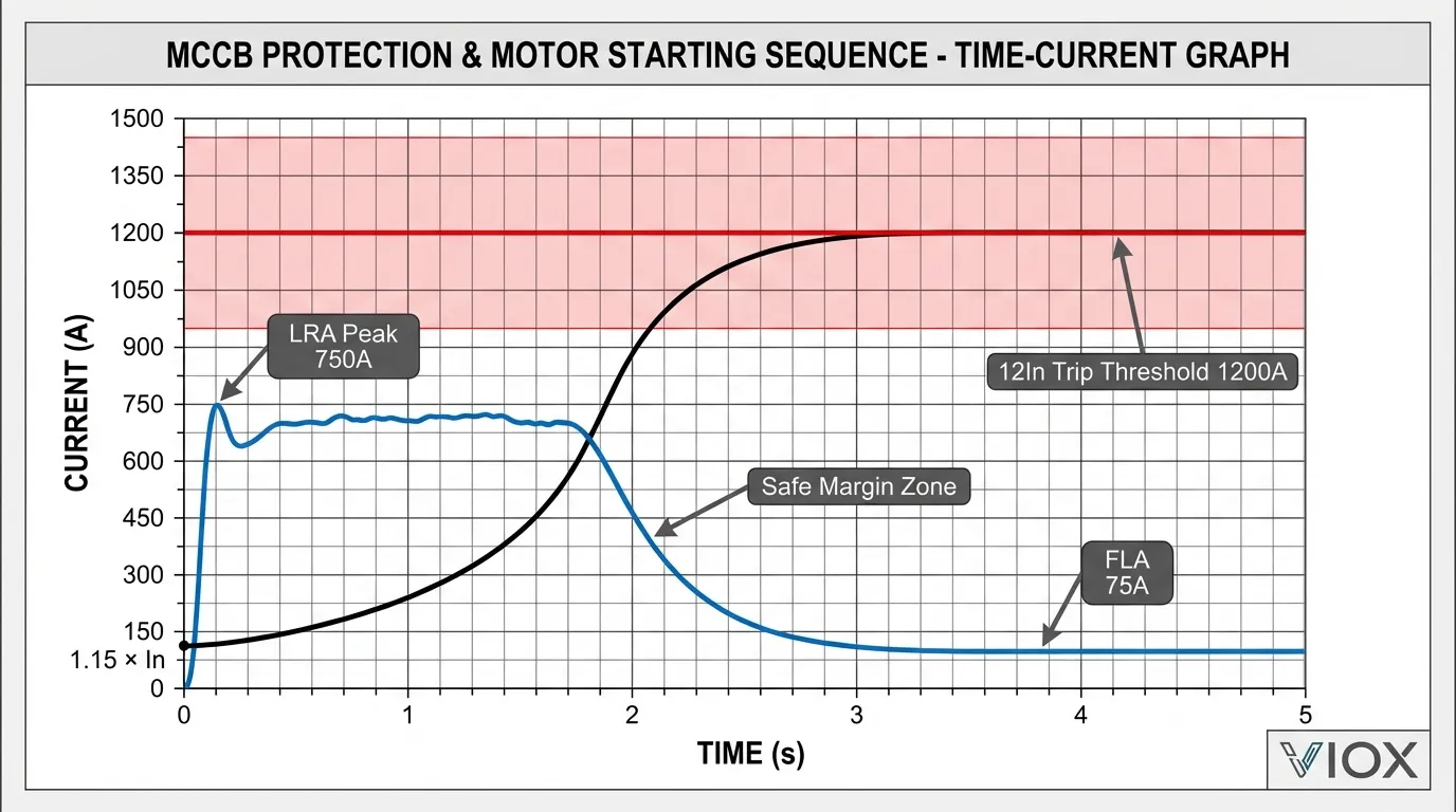
Case 2: 37kW Direct-Start Motor (Heavy Inductive Load)
System Parameters:
- Motor rating: 37kW (50HP), 400V three-phase
- Full load current: 70-75A (varies with efficiency and power factor)
- Starting method: Direct-on-line (across-the-line)
- Locked rotor current: 7× FLA = 490-525A (symmetrical RMS)
- Asymmetrical peak: 1.5× symmetrical = 735-788A
MCCB Selection:
- Frame rating: 100A thermal-magnetic MCCB
- Continuous current setting: 100A (provides 25-30% margin above FLA)
- Instantaneous trip setting: 12In (1,200A)
Technical Justification: Direct-on-line motor starting represents one of the most demanding applications for instantaneous trip coordination. The motor’s locked rotor current persists for 1-3 seconds during acceleration, depending on load inertia and torque characteristics. During this interval, the MCCB’s thermal element begins accumulating heat, but the instantaneous element must remain stable despite current levels approaching 10× the breaker’s continuous rating.
The 12In setting (1,200A trip threshold with ±20% tolerance, meaning 960-1,440A actual trip range) provides critical margin above the motor’s asymmetrical peak inrush of approximately 750A. This 25-50% safety factor accounts for supply voltage variations, motor aging effects that increase starting current, and breaker tolerance stack-up. Field experience across thousands of motor installations confirms that 12In settings eliminate nuisance tripping while maintaining protection integrity.
The 20-25% margin between breaker continuous rating (100A) and motor FLA (70-75A) serves multiple purposes. It accommodates the motor’s service factor operation, prevents thermal element nuisance trips during brief overload conditions, and provides derating margin for elevated ambient temperatures. In enclosures where ambient exceeds 40°C, this margin becomes essential—many MCCB manufacturers specify 0.5-1.0% derating per degree Celsius above 40°C reference temperature.
Short-circuit protection remains robust despite the elevated instantaneous setting. Available fault current at typical motor terminals ranges from 10,000A to 50,000A depending on transformer size and cable length. Even at 12In (1,200A), the breaker responds within 0.01-0.02 seconds to faults exceeding this threshold, well within the motor’s and cable’s withstand capabilities. The MCCB short-time delay and Icw rating becomes relevant only in coordinated systems with downstream protection.
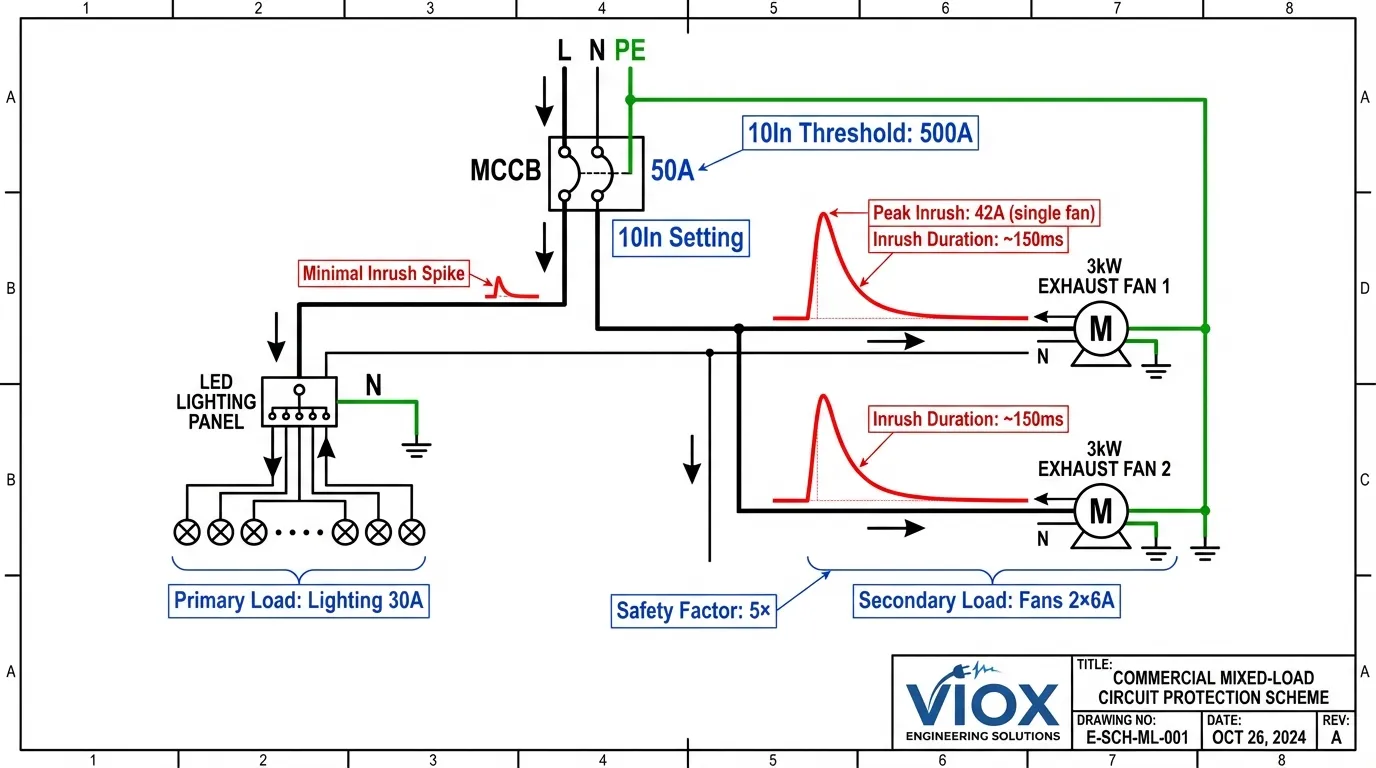
Case 3: Commercial Mixed Load (Lighting + Small Motors)
System Parameters:
- LED lighting load: 30A calculated demand
- Two 3kW exhaust fans: 6A each FLA, 42A each at startup (7× multiplier)
- Total continuous load: 42A
- Peak simultaneous inrush: 30A (lighting) + 42A (one fan starting) = 72A
MCCB Selection:
- Frame rating: 50A thermal-magnetic MCCB
- Continuous current setting: 50A
- Instantaneous trip setting: 10In (500A)
Technical Justification: Mixed-load circuits require instantaneous settings that accommodate the most demanding transient while optimizing protection for the primary load. In this commercial scenario, lighting constitutes the dominant continuous load (71% of total), with ventilation fans serving as secondary loads with intermittent operation. The selection philosophy prioritizes the primary load characteristic while verifying adequate margin for secondary load transients.
Small single-phase or three-phase fans exhibit starting currents similar to larger motors—typically 6-8× FLA depending on design. A 3kW fan drawing 6A continuous produces approximately 42A inrush during direct starting. However, the brief duration (typically 0.5-1.0 seconds for small motors with low inertia) and the fact that only one fan starts at a time in normal operation means the aggregate circuit inrush rarely exceeds 100A. The 10In setting (500A threshold) provides a 5:1 margin above this transient, effectively eliminating nuisance trip risk.
This application demonstrates an important principle: instantaneous settings need not accommodate simultaneous worst-case conditions for all loads unless operational requirements dictate such scenarios. Commercial ventilation systems typically employ sequenced starting through building automation systems, preventing simultaneous energization. Even in manual operation, the probability of both fans starting within the same half-cycle remains negligible. Engineering judgment permits optimization based on realistic operating profiles rather than theoretical worst-case stack-up.
The decision against 12In merits explanation. While 12In (600A for a 50A breaker) would provide additional margin, it offers no practical benefit in this application. The existing 10In setting already exceeds the realistic inrush by 5×, and the higher setting would degrade short-circuit protection and complicate coordination with upstream devices. This illustrates a key principle: instantaneous settings should be just high enough to prevent nuisance trips, not arbitrarily maximized. Understanding circuit breaker trip curves helps engineers make these optimization decisions.
Selection Decision Framework
Choosing between 10In and 12In instantaneous settings requires systematic evaluation of load characteristics, starting methods, and system coordination requirements. The following framework provides a structured approach applicable across industrial, commercial, and infrastructure applications.
Step 1: Load Classification
Begin by categorizing the circuit’s primary load type. Resistive loads (heating elements, incandescent lighting, resistive controls) exhibit minimal or no inrush current—typically less than 1.5× steady-state current for microseconds. These loads universally permit 10In settings. Capacitive loads (power factor correction capacitors, electronic power supplies with bulk capacitors) produce brief high-magnitude inrush but with duration measured in milliseconds. Modern designs incorporate inrush limiting, making 10In appropriate for most applications.
Inductive loads demand careful analysis. Small motors below 5kW with low-inertia loads (fans, small pumps) typically start within 0.5-1.0 seconds with inrush of 6-7× FLA. Medium motors from 5-50kW with moderate inertia (larger pumps, compressors, conveyors) require 1-3 seconds starting time with 7-8× FLA inrush. Large motors above 50kW or any motor driving high-inertia loads (flywheels, crushers, large fans) may require 3-10 seconds with inrush approaching 8-10× FLA. The motor’s starting method significantly impacts these values—star-delta starting reduces inrush to approximately 33% of DOL values, while soft starters and variable frequency drives nearly eliminate the issue.
Step 2: Inrush Current Calculation
For motor loads, obtain the locked rotor current (LRC or LRA) from the motor nameplate or manufacturer data. If unavailable, use conservative estimates: 7× FLA for standard efficiency motors, 8× FLA for high-efficiency designs. Calculate the asymmetrical peak by multiplying the symmetrical RMS value by 1.5 for worst-case scenarios. This asymmetrical component results from the DC offset that occurs when the motor energizes at an unfavorable point on the AC waveform.
For mixed loads, sum the continuous current of all loads plus the maximum inrush of the single largest inductive load. Do not sum inrush currents of multiple motors unless they genuinely start simultaneously through interlocked control schemes. This realistic assessment prevents over-conservative settings that degrade protection.
Step 3: Setting Selection
Apply the following rules: If maximum inrush (including asymmetrical peak) remains below 7× the breaker’s continuous rating, select 10In. If maximum inrush falls between 7× and 10× the breaker’s continuous rating, select 12In. If maximum inrush exceeds 10× the breaker’s continuous rating, consider alternative starting methods (star-delta, soft starter, VFD) or use a motor circuit protector with higher adjustable instantaneous range.
Verify that your selected setting provides minimum 20% margin above calculated peak inrush. This margin accounts for breaker tolerance (typically ±20%), supply voltage variations (±10% per ANSI C84.1), motor aging effects, and ambient temperature impacts on both motor and breaker performance.
Step 4: Coordination Verification
The instantaneous setting must coordinate with both upstream and downstream protective devices. For upstream coordination, verify that your setting falls below the upstream device’s instantaneous threshold or within its time-delayed region to ensure selectivity. For downstream coordination with motor overload relays or smaller branch circuit breakers, confirm that your instantaneous setting exceeds their maximum trip point to prevent sympathetic tripping during downstream faults.
Modern electronic trip units simplify this process by offering adjustable instantaneous settings in 0.5In or 1In increments. Thermal-magnetic units typically offer fixed settings (often 10In for distribution, 12In for motor protection) or limited adjustment ranges. Understanding your specific breaker’s capabilities proves essential—consult manufacturer trip curves and setting tables rather than making assumptions based on breaker size alone.
Critical Considerations and Common Mistakes
Temperature Derating Requirements
MCCB ratings assume a 40°C (104°F) ambient temperature reference. Installations in high-temperature environments require derating of the continuous current rating, which indirectly affects instantaneous trip coordination. Most manufacturers specify 0.5-1.0% derating per degree Celsius above 40°C. A 100A breaker operating in a 60°C enclosure may require derating to 90A continuous capacity. This derating affects only the thermal element; the instantaneous setting remains referenced to the nameplate rating (In). However, the reduced thermal capacity may necessitate selecting a larger frame size, which then requires recalculating the appropriate instantaneous multiplier.
Altitude presents similar challenges. Above 2,000 meters (6,600 feet), reduced air density degrades both thermal dissipation and dielectric strength. IEC 60947-2 and UL 489 standards specify derating factors, typically 0.5% per 100 meters above 2,000 meters. High-altitude installations in hot climates face compound derating that can reduce effective breaker capacity by 20-30%. Understanding electrical derating factors prevents field failures and ensures code compliance.
MCB vs MCCB Confusion
A critical distinction that trips up many engineers: miniature circuit breakers (MCBs) and molded case circuit breakers (MCCBs) use fundamentally different specification systems. MCBs employ trip curve designations (B, C, D, K, Z) that define both thermal and instantaneous characteristics as a package. A “C curve” MCB trips instantaneously at 5-10× In, while a “D curve” trips at 10-20× In. These curves are fixed and non-adjustable.
MCCBs, particularly those with electronic trip units, specify long-time (thermal), short-time, and instantaneous settings independently. You might encounter an MCCB with “10In” instantaneous setting that has nothing to do with MCB curve types. Confusing these systems leads to specification errors and field problems. When reviewing MCCB vs MCB differences, remember that MCCBs offer flexibility that MCBs cannot provide, but this flexibility demands more careful engineering.
Avoiding Over-Conservative Settings
A persistent mistake involves selecting 12In “to be safe” for all applications. This approach degrades protection in several ways. First, higher instantaneous settings extend fault-clearing time for currents just above the threshold, increasing arc energy and equipment damage. Second, elevated settings complicate selective coordination with upstream devices, potentially causing unnecessary outages during downstream faults. Third, they may violate code requirements for maximum fault-clearing time based on conductor ampacity and insulation ratings.
The inverse error—selecting 10In for all motor applications to “improve protection”—causes equally serious problems. Nuisance tripping during motor starting creates operational headaches, tempts operators to defeat protection, and masks genuine problems. Frequent tripping also degrades breaker contacts and mechanisms, reducing service life and reliability. The correct approach matches the setting to the application based on measured or calculated load characteristics, not arbitrary conservatism in either direction.
Verification Testing
After installation, verify instantaneous trip settings through proper testing procedures. For critical motor applications, monitor starting current with a power quality analyzer or recording ammeter during actual motor starts. Confirm that peak inrush remains below 80% of the calculated instantaneous trip threshold. If inrush exceeds this level, investigate motor condition (bearing wear, rotor bar damage, or winding faults can increase starting current), supply voltage adequacy, or mechanical load issues before adjusting breaker settings.
For distribution circuits, verify that the instantaneous setting exceeds maximum measured inrush by at least 2:1. Lower margins suggest potential nuisance trip risks during unusual but legitimate operating conditions. Testing should occur under realistic conditions—full load, normal ambient temperature, and typical supply voltage—rather than ideal laboratory conditions.
Comparison Table: Application-Specific Settings
| Application Type | Typical Load Current | Recommended MCCB Size | Instantaneous Setting | Peak Inrush | Safety Margin |
|---|---|---|---|---|---|
| LED Lighting Only | 80A | 100A | 10In (1,000A) | ~120A | 8.3× |
| Office Receptacles | 45A | 50A | 10In (500A) | ~90A | 5.6× |
| 37kW Motor DOL | 70A | 100A | 12In (1,200A) | ~750A | 1.6× |
| 75kW Motor DOL | 140A | 160A | 12In (1,920A) | ~1,500A | 1.3× |
| Mixed (Lighting + Small Motors) | 42A | 50A | 10In (500A) | ~100A | 5.0× |
| Transformer Primary (75kVA) | 110A | 125A | 10In (1,250A) | ~600A | 2.1× |
| Welding Equipment | 60A | 100A | 12In (1,200A) | ~900A | 1.3× |
| Data Center PDU | 200A | 250A | 10In (2,500A) | ~400A | 6.3× |
| HVAC Package Unit | 85A | 100A | 12In (1,200A) | ~850A | 1.4× |
| Commercial Kitchen | 95A | 125A | 10In (1,250A) | ~150A | 8.3× |
This table demonstrates how safety margins vary dramatically based on load characteristics. Resistive and electronic loads achieve margins of 5-8×, while motor loads operate with tighter margins of 1.3-2.0×. Both scenarios provide adequate protection when properly applied, but the motor applications leave less room for error in calculation or measurement.
Integration with Modern Protection Systems
Contemporary electrical installations increasingly employ coordinated protection schemes that extend beyond simple overcurrent protection. Ground fault protection, arc fault detection, and power quality monitoring integrate with traditional thermal-magnetic protection to create comprehensive safety systems. The instantaneous trip setting plays a crucial role in these coordinated schemes.
Ground fault protection typically operates at much lower current thresholds than instantaneous overcurrent protection—often 30-300mA for personnel protection or 100-1,000mA for equipment protection. These systems must coordinate with instantaneous settings to ensure that ground faults clear through the appropriate protective device. A poorly coordinated system might see the instantaneous element trip on a ground fault that should have cleared through the ground fault relay, causing unnecessary outage scope.
Arc fault protection presents different challenges. Arc fault detection devices (AFDDs) sense the characteristic current and voltage signatures of series and parallel arcing faults. These devices must coordinate with both thermal and instantaneous elements to prevent nuisance tripping while ensuring genuine arc faults receive priority clearing. The instantaneous setting affects this coordination—excessively high settings may allow arc faults to persist longer before reaching the instantaneous threshold, while very low settings may interfere with AFDD discrimination algorithms.
Modern electronic trip units offer advanced coordination features including zone-selective interlocking, which uses communication between breakers to achieve selective coordination even when time-current curves overlap. These systems may temporarily inhibit instantaneous tripping on upstream devices when downstream devices detect faults within their zones. Understanding how instantaneous settings interact with these advanced features ensures optimal system performance and prevents unexpected behavior during fault conditions.
FAQ Section
Q: Can I use a 10In setting for a motor if I upsize the breaker significantly?
A: Oversizing the breaker frame to use a lower instantaneous multiplier generally proves counterproductive. While a 150A breaker at 10In (1,500A) might accommodate a 70A motor’s inrush, the thermal element becomes mismatched to the motor’s actual current, providing inadequate overload protection. The proper approach uses a correctly sized breaker (100A for 70A motor) with appropriate instantaneous setting (12In) and relies on separate overload protection through a motor starter’s thermal overload relay.
Q: How do soft starters and VFDs affect instantaneous trip selection?
A: Soft starters and variable frequency drives dramatically reduce or eliminate motor starting inrush, typically limiting starting current to 1.5-3× FLA. This permits using 10In instantaneous settings even for large motors. However, verify the drive manufacturer’s specifications for maximum output current during starting and fault conditions. Some drives can produce high instantaneous currents during output short circuits that may require coordination consideration.
Q: What if my calculated inrush falls right at the instantaneous threshold?
A: Insufficient margin invites nuisance tripping due to tolerance stack-up, voltage variations, and aging effects. Minimum recommended margin is 20% above peak inrush. If your calculation shows 1,000A inrush and you’re considering a 10In setting that trips at 1,000A nominal, you face high nuisance trip risk. Either select the next higher multiplier (12In) or reduce inrush through alternative starting methods.
Q: Do electronic trip units offer finer instantaneous adjustment than thermal-magnetic units?
A: Yes. Electronic trip units typically offer instantaneous adjustment in 0.5In or 1In increments across a wide range (often 2In to 15In), while thermal-magnetic units usually provide fixed settings or limited adjustment (typically 10In or 12In). This flexibility makes electronic units preferable for applications requiring precise coordination or unusual load characteristics. However, electronic units cost significantly more and may not be justified for simple applications.
Q: How does the instantaneous setting affect arc flash incident energy?
A: Lower instantaneous settings reduce fault-clearing time, which directly reduces arc flash incident energy. The relationship follows E = P × t, where energy equals power times time. Reducing clearing time from 0.02 seconds (12In) to 0.015 seconds (10In) cuts incident energy by 25%. However, this benefit only applies to faults above the instantaneous threshold. For comprehensive arc flash reduction, consider maintenance modes, zone-selective interlocking, or arc flash relays rather than relying solely on instantaneous setting optimization.
Q: Can I adjust instantaneous settings in the field, or must I specify them at purchase?
A: Thermal-magnetic MCCBs typically have fixed instantaneous settings determined at manufacture, though some models offer limited field adjustment via mechanical dials or switches. Electronic trip units universally offer field-adjustable instantaneous settings through digital interfaces or DIP switches. Always verify adjustment capability before purchase if field tuning is required. Document all field adjustments and verify coordination after any changes.
Conclusion
Selecting between 10In and 12In instantaneous trip settings represents a fundamental protection engineering decision that impacts both safety and operational reliability. The straightforward rule—10In for distribution loads, 12In for motor loads—provides a reliable starting point, but optimal protection requires understanding the technical principles underlying these recommendations. Resistive and electronic loads with minimal inrush permit aggressive 10In settings that enhance fault clearing and coordination. Motor loads with significant starting current demand 12In settings that prevent nuisance tripping while maintaining robust short-circuit protection.
The selection process demands accurate load characterization, realistic inrush calculation, and verification of adequate safety margins. Common mistakes including MCCB-MCB confusion, over-conservative settings, and neglecting ambient temperature effects can compromise protection effectiveness. Modern installations with integrated ground fault, arc fault, and communication-based coordination require additional consideration of how instantaneous settings interact with these advanced protective functions.
Proper instantaneous trip selection eliminates the frustrating cycle of nuisance trips and inappropriate responses to genuine faults. It enables motors to start reliably, protects distribution circuits aggressively, and creates the foundation for selective coordination throughout the electrical system. When combined with appropriate breaker sizing, thermal element selection, and system-level coordination studies, correct instantaneous trip settings deliver the reliable protection that modern electrical installations demand. For complex applications or systems with critical coordination requirements, consult manufacturer application guides and consider engaging protection engineering specialists to verify your selections through detailed time-current coordination studies.
Related Articles:
- What is a Molded Case Circuit Breaker (MCCB)
- Understanding Trip Curves
- MCCB vs MCB: Complete Comparison Guide
- Circuit Breaker Ratings: Icu, Ics, Icw, Icm Explained
- Motor Circuit Protector vs Thermal Magnetic Breakers
- Star-Delta Starter Wiring and Sizing Guide
- Electrical Derating: Temperature, Altitude & Grouping Factors
VIOX Electric specializes in manufacturing high-quality MCCBs, MCBs, and electrical protection devices for industrial and commercial applications. Our technical team provides application support and coordination studies to ensure optimal protection system design. Contact us for product specifications, custom solutions, or technical consultation.
