VIOX Electric
Language

産業用および商業用電気システムにおける三相SPDの選定方法

How to Size a 3-Phase SPD: Industrial Selection Guide

執筆者:

カテゴリ:

A three-phase surge protective device is not sized from panel amperes and it should not be selected by choosing the largest kA number. The correct specification starts with the voltage across each connected protection mode, the earthing system and the installation boundary. Only then can you select SPD Type, topology, Uc, Up, Iimp/In/Imax and short-circuit protection.

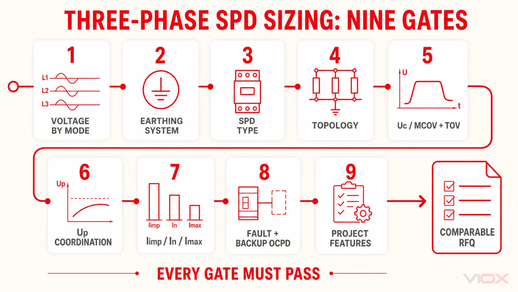
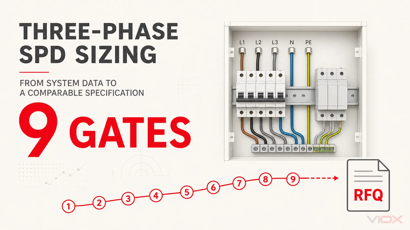
Use the nine gates below in order. Each gate can disqualify a product; passing only the current-rating gate is not enough.

Three-Phase SPD Sizing: The Required Inputs

Collect this information before comparing models:

入力 Record from the project
電源 Nominal and maximum L-L voltage, L-N voltage where present, frequency
導体 Three-wire or four-wire; L1/L2/L3, N, PE or PEN
接地 TN-S, TN-C-S, TN-C, TT, IT or project-defined arrangement at this panel
所在地 Service origin, main switchboard, distribution board or near final equipment
Exposure External lightning protection system, overhead supply, lightning risk and upstream SPD
装置 Required impulse withstand/protection objective and criticality
短絡電流 Prospective short-circuit current and upstream fuse/breaker
インストール Space, environment, lead route, status and remote-alarm requirement
規格 IEC/EN, UL or other project basis; do not mix classifications

The output is a specification, not just “a 40 kA SPD.”

Nine-gate three-phase SPD sizing sequence from system voltage and earthing through fault protection and the final RFQ.
A comparable three-phase SPD specification must pass all nine gates; a large discharge-current figure alone is not a complete selection.

Gate 1: Define Voltage by Protection Mode

Record both line-to-line and line-to-neutral voltage. A 400/230 V system and a 480 V system may both be called “three phase,” but the voltage continuously applied to an SPD element depends on whether that element is connected L-N, L-PE, L-L or N-PE.

Also identify the highest expected normal power-frequency voltage at the installation point. Do not confuse this with a surge. Voltage tolerance, transformer regulation, generation modes and system faults can change the stress across a protection mode.

Specification output: nominal system voltage, maximum normal voltage and voltage across every proposed protection mode.

Gate 2: Identify the Earthing System at This Panel

Do not select topology from the building’s general description alone. Identify whether neutral and PE are separate or combined at the actual SPD location and where any PEN separation or N-PE bond occurs.

  • TN-S/TN-C-S downstream of separation: L, N and PE are distinct at the panel; L-N and N-PE coordination is commonly relevant.
  • TN-C: the conductor arrangement includes PEN; use only a topology approved for that point and do not create an artificial neutral-earth separation.
  • TT: N-PE behavior and temporary overvoltage stresses require explicit consideration; 3+1 arrangements are commonly used in IEC-oriented designs, but the exact choice remains project- and product-specific.
  • IT: first-fault conditions can raise voltage to earth on healthy conductors. Uc and topology must be verified for the real IT configuration and fault condition.

使用する TN, TT and IT earthing guide for system definitions.

Specification output: earthing system, N/PE/PEN arrangement and bond location.

Gate 3: Select the SPD Type from Location and Exposure

In the IEC framework, Type identifies standardized surge duty, not pole count:

タイプ Main duty parameter Typical design role
タイプ1 アイムプ, commonly associated with 10/350 µs testing Lightning-current handling at an origin or LPZ boundary where the risk design requires it
タイプ2 and, where declared, アイマックス, commonly with 8/20 µs current Distribution-level limitation of induced and switching surges
タイプ3 Combination-wave/terminal-equipment coordination Fine protection close to sensitive equipment, coordinated with upstream SPDs
タイプ1+2 Declared performance for both duties Combined application where both sets of requirements are satisfied

An external lightning protection system, lightning-current risk assessment, overhead service and installation boundary may drive a Type 1 requirement. A downstream distribution board does not automatically need Type 1 merely because it is industrial.

IEC Type 1/2/3 and UL 1449 SPD Types are not interchangeable labels. If the project is UL-based, specify the UL category, nominal system configuration, MCOV, VPR, SCCR and installation location under that framework. See the detailed Type 1 vs Type 2 vs Type 3 ガイド.

Specification output: standards framework, SPD Type and installation boundary.

Gate 4: Choose Topology and Protection Modes

Topology must fit the conductors and earthing system:

  • 3+0: three protection paths, with the exact connected modes defined by the product diagram.
  • 4+0: four voltage-limiting paths in common market terminology; supplier notation and modes must be verified.
  • 3+1: commonly three phase-to-neutral voltage-limiting paths plus a coordinated N-PE switching path.

Do not equate four physical modules with a universal “four-pole” circuit. Read the internal circuit diagram and declare the required modes: L-N, L-PE, L-L and/or N-PE. The SPDトポロジーガイド そして 3-pole vs 4-pole guide cover this decision in depth.

Specification output: conductor count, topology and required modes of protection.

Gate 5: Select Uc or MCOV—and Check TOV Behavior

ユーシー is the maximum continuous operating voltage that may be applied to the SPD under its declared conditions. Select it for the voltage across each mode, not from the line-to-line system label alone.

Uc must be high enough to avoid operation or accelerated aging during normal voltage conditions, but choosing an unnecessarily high Uc can result in a less favorable protection level. Use manufacturer tables for the specific earthing system.

Also verify the SPD’s behavior under temporary power-frequency overvoltage (TOV). A TOV is not simply an ordinary long-term supply deviation. Its significance depends on magnitude, duration, earthing system and fault, equipment withstand, SPD response and local installation rules. A generic voltage protector is not a substitute for checking declared SPD TOV behavior.

For a deeper distinction, read サージ防護デバイス(SPD)におけるImax対In.

Specification output: Uc/MCOV for each protection mode and required TOV behavior.

Gate 6: Coordinate Up with the Protected Equipment

is the declared voltage protection level under specified tests. It must support coordination with the equipment’s impulse withstand and upstream/downstream protection plan.

Do not simply select the lowest number on a catalog page:

  • Compare Up only on the same standard and protection-mode basis.
  • Allow for voltage added by connection-lead inductance in the real installation.
  • Consider cable distance and coordinated downstream SPDs where required.
  • Confirm that Uc and TOV suitability remain correct; a low Up cannot compensate for the wrong continuous-voltage rating.

Specification output: maximum acceptable declared Up by mode, equipment withstand basis and installation coordination note.

Gate 7: Specify Iimp, In and Imax Correctly

These values are not interchangeable kA ratings:

評価 Selection use Comparison rule
アイムプ タイプ1の雷電流耐量 Compare per pole/mode with the same 10/350 µs test basis and charge/energy context
Nominal discharge-current duty Compare with the same 8/20 µs basis, mode and standard
アイマックス Maximum discharge current for products that declare it Treat as a maximum test value, not proof of repeated duty or Type 1 capability

The required duty comes from the risk assessment, lightning protection design, installation level, coordination and applicable rules. There is no defensible universal kA value for every commercial or industrial panel. The In vs Imax guide explains the ratings without turning them into a false sizing shortcut.

Specification output: required Iimp for Type 1 duty and/or In plus Imax where relevant, each with waveform, mode and per-pole/total basis.

Gate 8: Verify Short-Circuit and Backup Protection

An SPD can reach end of life or fail under abnormal system conditions. The branch must be able to disconnect safely at the available fault level.

記録および照合:

  1. Prospective short-circuit current at the installation point.
  2. SPD SCCR or applicable short-circuit withstand/current declaration such as Isccr.
  3. Maximum permitted upstream fuse or breaker.
  4. Manufacturer-specified external backup fuse/breaker, if required.
  5. Coordination and selectivity expectations for the upstream distribution system.
  6. Follow-current extinguishing capability where relevant to the SPD technology.

An internal thermal disconnector and an external short-circuit protective device perform different functions. Never choose the backup device from panel current alone or replace it with a larger rating without the manufacturer’s coordination data.

Specification output: available fault current, applicable short-circuit declaration, upstream device and dedicated backup device.

Gate 9: Complete the Industrial Specification

Electrical ratings are only part of a usable RFQ. Add:

  • DIN-rail or panel-mounted format and available modules
  • Pluggable or fixed cartridges
  • Visual status indication and remote changeover contact
  • Operating temperature, altitude and derating requirements
  • Enclosure/pollution/environmental conditions
  • Terminal range, conductor requirements and torque data
  • Required certification and test documentation
  • Replaceable-module coding and maintenance access
  • Coordination with upstream/downstream SPDs
  • Maximum practical connection-path objective

Worked Example: 400/230 V TN-S Distribution Board

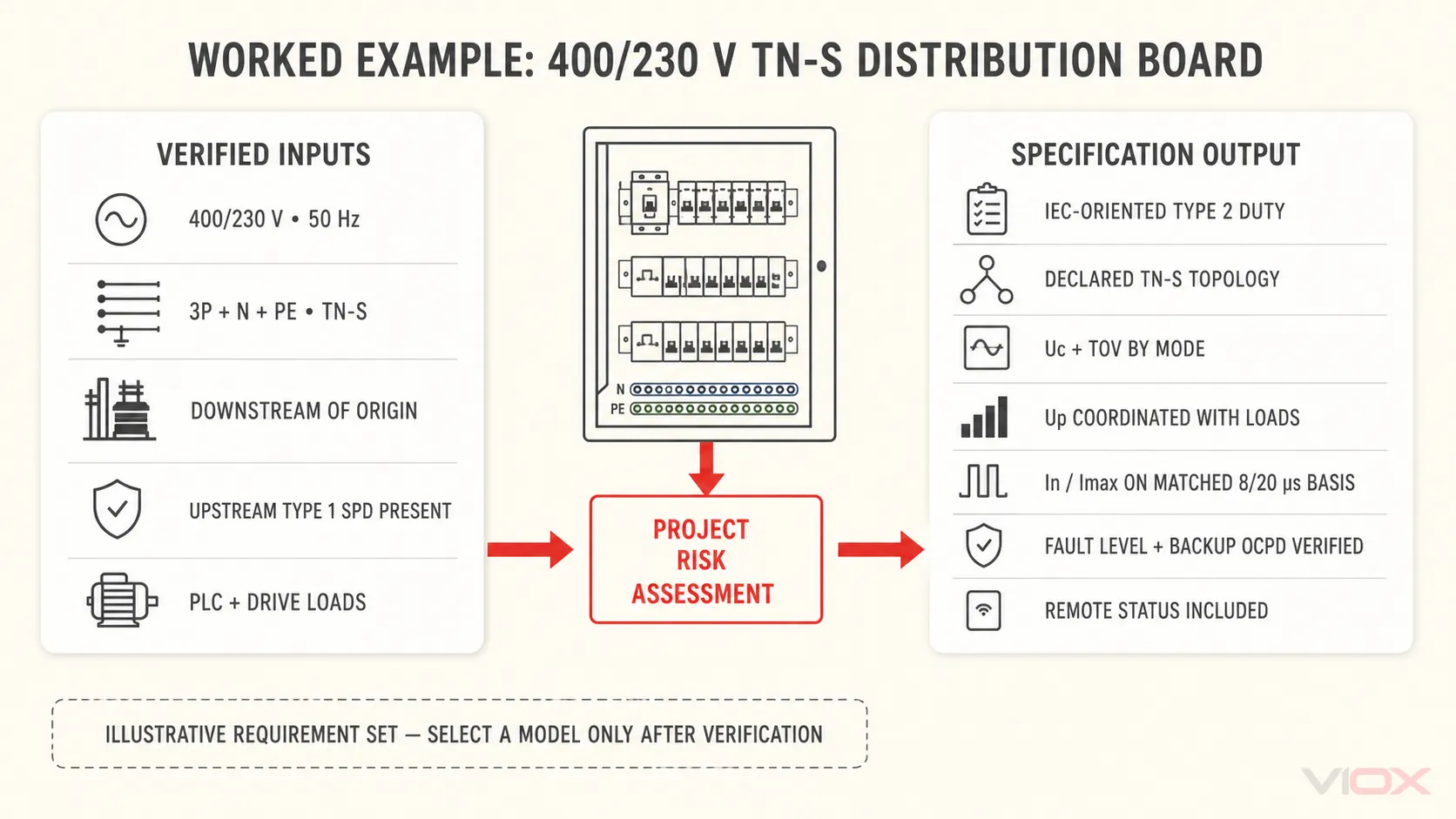
Assume a project records a 400/230 V, 50 Hz, three-phase four-wire TN-S distribution board downstream of the service. There is an upstream Type 1 SPD at the origin, no separate direct-lightning-current boundary at this board, and sensitive PLC and drive equipment is supplied downstream.

The correct result is not an invented catalog model. It is a requirement set:

  • IEC-oriented Type 2 duty at this distribution level, subject to the project risk assessment.
  • Topology approved for 3P+N TN-S, with exact L-N/N-PE or other required modes declared.
  • Uc selected from the manufacturer’s TN-S table against the actual voltage in each mode and maximum normal condition.
  • TOV behavior compatible with the system and local rules.
  • Up coordinated with downstream equipment withstand and corrected for the intended lead arrangement.
  • In and Imax, where declared, selected from the project’s surge-duty requirement on a matched 8/20 µs basis.
  • Available fault current checked against SCCR/Isccr and the manufacturer backup-protection table.
  • Remote indication included because the board is maintained centrally.

Only after these statements are complete should a model be selected.

Worked three-phase SPD specification framework for a 400/230 V TN-S distribution board downstream of the origin.
The worked example converts verified project inputs into a requirement set without inventing universal Uc, Up or discharge-current values.

Copy-Ready Three-Phase SPD RFQ Worksheet

Application / panel:
Standards framework and market:
Nominal voltage: ____ V L-L / ____ V L-N
Maximum normal voltage and frequency:
Conductors: L1 / L2 / L3 / N / PE or PEN
Earthing system and bond/PEN separation location:
Installation boundary and upstream SPD:
External LPS / lightning risk result:
Required SPD Type:
Required topology and protection modes:
Uc / MCOV by mode:
Required TOV behavior:
Maximum acceptable Up by mode:
Iimp requirement with waveform and per-pole/total basis:
In requirement with waveform and mode:
Imax requirement, where used, with waveform and mode:
Prospective short-circuit current:
Required SCCR or applicable declaration such as Isccr:
Upstream protective device:
Required external backup fuse/breaker:
Mounting, environment and module count:
Visual / remote status requirement:
Lead-route constraint and coordination notes:
Required certificates and documentation:

使用する SPDデータシートガイド to verify supplier responses line by line. Physical installation then follows the SPD wiring guide.

最終選定ルール

A defensible three-phase SPD specification must pass every gate:

system voltage → earthing → installation Type → topology → Uc/TOV → Up → Iimp/In/Imax → fault/backup protection → project features

If a supplier quote omits protection modes, test waveforms or short-circuit coordination, it is not yet comparable. Send the completed worksheet and single-line diagram to the VIOX SPD製品チーム for model-level verification.

参考文献