Na této stránce
Třífázový svodič přepětí SPD se ne dimenzuje podle ampérové hodnoty rozváděče a neměl by se vybírat podle nejvyšší hodnoty kA. Správná specifikace začíná napětím na každém připojeném ochranném režimu, systémem uzemnění a rozhraním instalace. Teprve poté můžete zvolit typ SPD, topologii, Uc, Up, Iimp/In/Imax a ochranu proti zkratu.
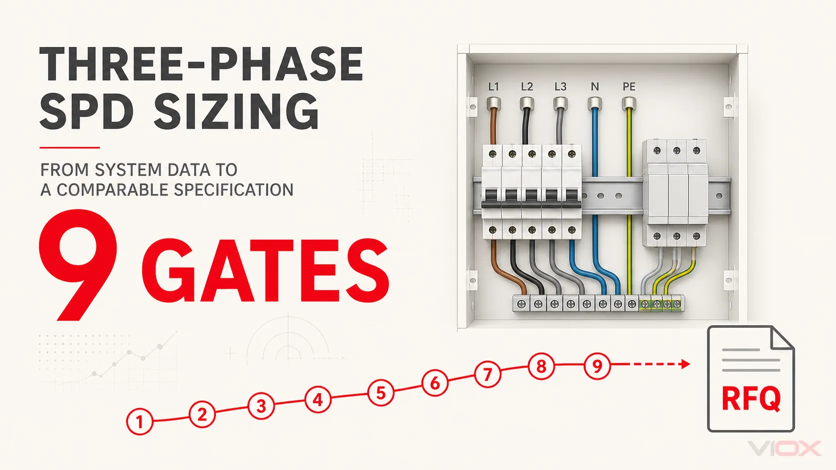
Použijte níže uvedených devět kroků v daném pořadí. Každý krok může produkt vyloučit; projití pouze krokem jmenovitého proudu nestačí.
Dimenzování třífázového SPD: Požadované vstupní údaje
Před porovnáním modelů shromážděte tyto informace:
| Vstup | Záznam z projektu |
|---|---|
| Napájení | Jmenovité a maximální napětí L-L, napětí L-N, je-li přítomno, frekvence |
| Vodiče | Třívodičové nebo čtyřvodičové; L1/L2/L3, N, PE nebo PEN |
| Zemnění | TN-S, TN-C-S, TN-C, TT, IT nebo projektově definované uspořádání v tomto rozváděči |
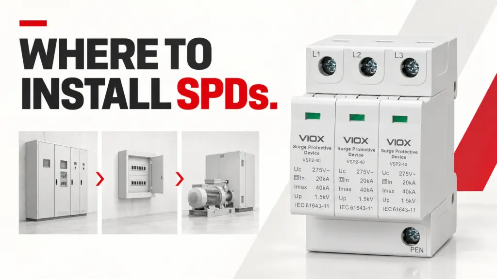
| Umístění | Zdroj napájení, hlavní rozváděč, podružný rozváděč nebo v blízkosti koncového zařízení |
| Expozice | Vnější systém ochrany před bleskem, venkovní napájení, riziko zásahu bleskem a předřazený SPD |
| Zařízení | Požadovaná impulzní odolnost/cíl ochrany a kritičnost |
| Poruchové zatížení | Předpokládaný zkratový proud a předřazená pojistka/jistič |
| Instalace | Prostor, prostředí, trasa vodičů, stav a požadavek na dálkovou signalizaci |
| Normy | IEC/EN, UL nebo jiný projektový základ; nekombinujte klasifikace |
Výstupem je specifikace, nikoliv pouze “40 kA SPD”.”
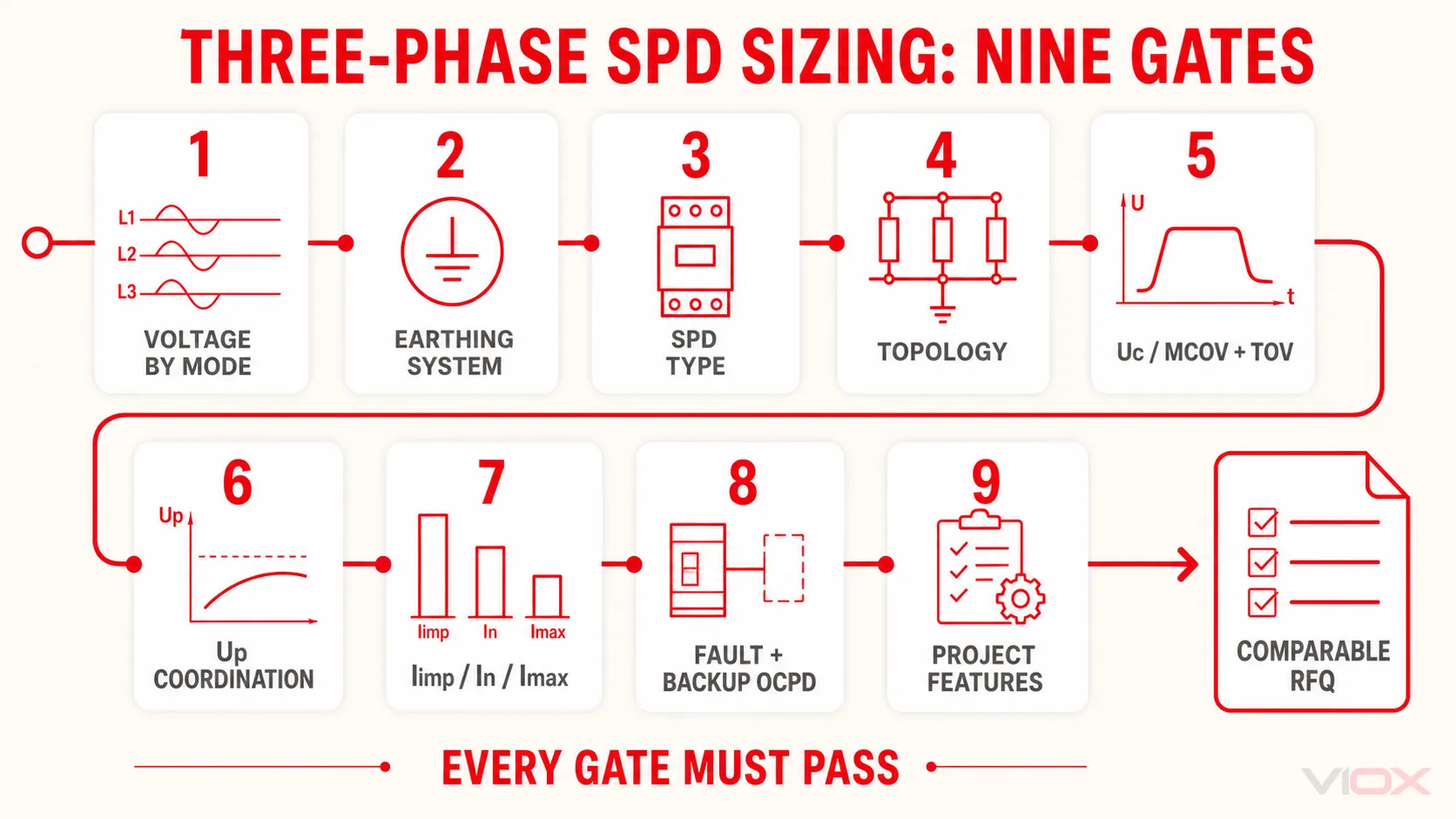
Brána 1: Definujte napětí podle režimu ochrany
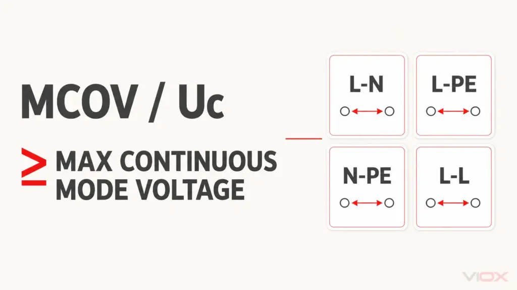
Zaznamenejte napětí mezi fázemi i mezi fází a nulovým vodičem. Systém 400/230 V a systém 480 V mohou být oba označovány jako “třífázové”, ale napětí trvale přivedené na prvek SPD závisí na tom, zda je tento prvek připojen L-N, L-PE, L-L nebo N-PE.
Dále určete nejvyšší očekávané normální napětí o výkonové frekvenci v místě instalace. Nezaměňujte jej s přepětím. Napěťová tolerance, regulace transformátoru, režimy generování a poruchy v elektrické soustavě mohou změnit namáhání napříč režimem ochrany.
Výstup specifikace: jmenovité napětí elektrické soustavy, maximální normální napětí a napětí napříč každým navrhovaným režimem ochrany.
Brána 2: Identifikujte systém uzemnění v tomto rozváděči
Nevybírejte topologii pouze na základě obecného popisu budovy. Identifikujte, zda jsou nulový vodič a PE odděleny nebo spojeny v konkrétním místě instalace SPD a kde dochází k jakémukoliv oddělení PEN nebo propojení N-PE.
- TN-S/TN-C-S za místem rozdělení: L, N a PE jsou v rozváděči oddělené; koordinace L-N a N-PE je běžně relevantní.
- TN-C: uspořádání vodičů zahrnuje PEN; použijte pouze topologii schválenou pro daný bod a nevytvářejte umělé oddělení středního a ochranného vodiče.
- TT: chování N-PE a namáhání přechodným přepětím vyžadují výslovné posouzení; v návrzích dle IEC se běžně používá uspořádání 3+1, ale přesná volba zůstává závislá na konkrétním projektu a produktu.
- IT: podmínky první poruchy mohou zvýšit napětí vůči zemi na zdravých vodičích. Uc a topologii je nutno ověřit pro reálnou konfiguraci IT a stav poruchy.
Použijte Průvodce uzemněním TN, TT a IT pro definice soustavy.
Výstup specifikace: systém uzemnění, uspořádání N/PE/PEN a umístění pospojování.
Brána 3: Vyberte typ SPD podle umístění a expozice
V rámci IEC identifikuje typ standardizovanou proudovou zatížitelnost přepěťové ochrany, nikoli počet pólů:
| Typ | Hlavní parametr zatížení | Typická návrhová úloha |
|---|---|---|
| Typ 1 | IMP, běžně spojováno s testováním 10/350 µs |
Svedení bleskového proudu na začátku instalace nebo na rozhraní zón bleskové ochrany (LPZ), kde to návrh rizik vyžaduje |
| Typ 2 | Na adrese a tam, kde je deklarováno, Imax, obvykle s proudem 8/20 µs |
Omezení indukovaných a spínacích přepětí na úrovni distribuce |
| Typ 3 | Koordinace kombinované vlny/koncového zařízení | Jemná ochrana v blízkosti citlivého zařízení, koordinovaná s předřazenými SPD |
| Typ 1+2 | Deklarovaný výkon pro obě zatížení | Kombinovaná aplikace, kde jsou splněny obě sady požadavků |
Vnější systém ochrany před bleskem, posouzení rizika bleskového proudu, venkovní vedení a hranice instalace mohou vyvolat požadavek na Typ 1. Následný rozváděč automaticky nevyžaduje Typ 1 pouze proto, že je průmyslový.
Typy SPD podle IEC 1/2/3 a UL 1449 nejsou zaměnitelné štítky. Pokud projekt vychází z normy UL, specifikujte kategorii UL, jmenovitou konfiguraci soustavy, MCOV, VPR, SCCR a místo instalace v rámci tohoto rámce. Viz podrobný Průvodce typem 1 vs. typem 2 vs. typem 3.
Výstup specifikace: rámec norem, typ SPD a hranici instalace.
Brána 4: Volba topologie a režimů ochrany
Topologie musí odpovídat vodičům a systému uzemnění:
- 3+0: tři ochranné cesty, s přesně připojenými režimy definovanými schématem produktu.
- 4+0: čtyři cesty omezující napětí v běžné obchodní terminologii; označení dodavatele a režimy musí být ověřeny.
- 3+1: běžně tři cesty omezující napětí mezi fází a nulovým vodičem plus koordinovaná spínací cesta N-PE.
Neztotožňujte čtyři fyzické moduly s univerzálním “čtyřpólovým” obvodem. Přečtěte si schéma vnitřního zapojení a deklarujte požadované režimy: L-N, L-PE, L-L a/nebo N-PE. Dále Průvodce topologií SPD a Průvodce 3pólovým a 4pólovým provedením podrobně se věnujte tomuto rozhodnutí.
Výstup specifikace: počet vodičů, topologie a požadované režimy ochrany.
Brána 5: Výběr Uc nebo MCOV – a kontrola chování při TOV
Univerzita v Utahu je maximální trvalé provozní napětí, které může být přivedeno na SPD za deklarovaných podmínek. Vybírejte jej podle napětí v každém režimu, nikoliv pouze podle označení fázového napětí soustavy.
Uc musí být dostatečně vysoké, aby se zabránilo aktivaci nebo zrychlenému stárnutí za podmínek normálního napětí, avšak volba zbytečně vysokého Uc může vést k méně příznivé úrovni ochrany. Použijte tabulky výrobce pro konkrétní systém uzemnění.
Také ověřte chování SPD při dočasném přepětí o síťovém kmitočtu (TOV). TOV není jen obyčejná dlouhodobá odchylka napájení. Jeho význam závisí na velikosti, trvání, systému uzemnění a poruše, odolnosti zařízení, reakci SPD a místních instalačních předpisech. Obecná napěťová ochrana nenahrazuje kontrolu deklarovaného chování SPD při TOV.
Pro hlubší rozlišení si přečtěte Uc vs Up u svodiče přepětí (SPD).
Výstup specifikace: Uc/MCOV pro každý režim ochrany a požadované chování při TOV.
Brána 6: Koordinace Up s chráněným zařízením
Nahoru je deklarovaná napěťová ochranná úroveň při stanovených zkouškách. Musí podporovat koordinaci s odolností zařízení vůči impulzům a plánem ochrany předřazených/následných zařízení.
Nevybírejte prostě nejnižší číslo na stránce katalogu:
- Porovnávejte Up pouze na základě stejné normy a režimu ochrany.
- Počítejte s napětím přidaným indukčností připojovacích vodičů ve skutečné instalaci.
- Zohledněte délku kabelu a v případě potřeby koordinované následné SPD.
- Ověřte, zda parametry Uc a vhodnost pro TOV zůstávají správné; nízká hodnota Up nemůže kompenzovat nesprávné jmenovité trvalé provozní napětí.
Výstup specifikace: maximální přípustné deklarované Up podle režimu, základ odolnosti zařízení a poznámka ke koordinaci instalace.
Brána 7: Správně specifikujte Iimp, In a Imax
Tyto hodnoty v kA nejsou zaměnitelné:
| Hodnocení | Použití při výběru | Pravidlo porovnání |
|---|---|---|
IMP |
Zatížení bleskovým proudem typu 1 | Porovnávejte na pól/režim se stejným zkušebním základem 10/350 µs a kontextem náboje/energie |
Na adrese |
Jmenovitý vybíjecí proud | Porovnávejte se stejným základem 8/20 µs, režimem a normou |
Imax |
Maximální vybíjecí proud pro produkty, které jej deklarují | Považujte za maximální zkušební hodnotu, nikoliv za důkaz opakovaného provozu nebo způsobilosti typu 1 |
Požadovaný provoz vyplývá z posouzení rizik, návrhu ochrany před bleskem, úrovně instalace, koordinace a platných norem. Neexistuje žádná obhajitelná univerzální hodnota kA pro každý komerční nebo průmyslový rozvaděč. Průvodce In vs Imax vysvětluje jmenovité hodnoty, aniž by je měnil na chybnou zkratku pro dimenzování.
Výstup specifikace: požadovaný Iimp pro provoz typu 1 a/nebo In plus Imax tam, kde je to relevantní, každý s průběhem, módem a na pól/celkově.
Brána 8: Ověření zkratové a záložní ochrany
SPD může dosáhnout konce životnosti nebo selhat za abnormálních podmínek v elektrické soustavě. Větev musí být schopna bezpečně vypnout při dostupné úrovni poruchového proudu.
Zaznamenejte a porovnejte:
- Předpokládaný zkratový proud v místě instalace.
- SPD
SCCRnebo platná deklarace odolnosti proti zkratu / zkratového proudu, jako jeIsccr. - Maximální povolená předřazená pojistka nebo jistič.
- Výrobcem specifikovaná externí záložní pojistka/jistič, je-li vyžadována.
- Požadavky na koordinaci a selektivitu pro nadřazenou distribuční soustavu.
- Schopnost zhášení následného proudu tam, kde je to relevantní pro technologii SPD.
Vnitřní tepelný odpojovač a externí zkratové ochranné zařízení plní odlišné funkce. Záložní zařízení nikdy nevolte pouze podle proudu v rozvaděči a nenahrazujte jej zařízením s vyšší jmenovitou hodnotou bez koordinačních údajů výrobce.
Výstup specifikace: dostupný poruchový proud, platná deklarace odolnosti proti zkratu, předřazené zařízení a určené záložní zařízení.
Brána 9: Dokončete průmyslovou specifikaci
Elektrické jmenovité hodnoty jsou pouze částí použitelné poptávky (RFQ). Přidejte:
- Formát pro montáž na lištu DIN nebo panel a dostupné moduly
- Zásuvné nebo pevné moduly
- Vizuální indikace stavu a dálkový přepínací kontakt
- Provozní teplota, nadmořská výška a požadavky na snížení výkonu
- Podmínky krytí/znečištění/prostředí
- Rozsah svorek, požadavky na vodiče a údaje o utahovacím momentu
- Požadovaná certifikace a dokumentace ke zkouškám
- Kódování vyměnitelných modulů a přístup pro údržbu
- Koordinace s předřazenými/následnými SPD
- Cíl maximální praktické délky připojovacího vedení
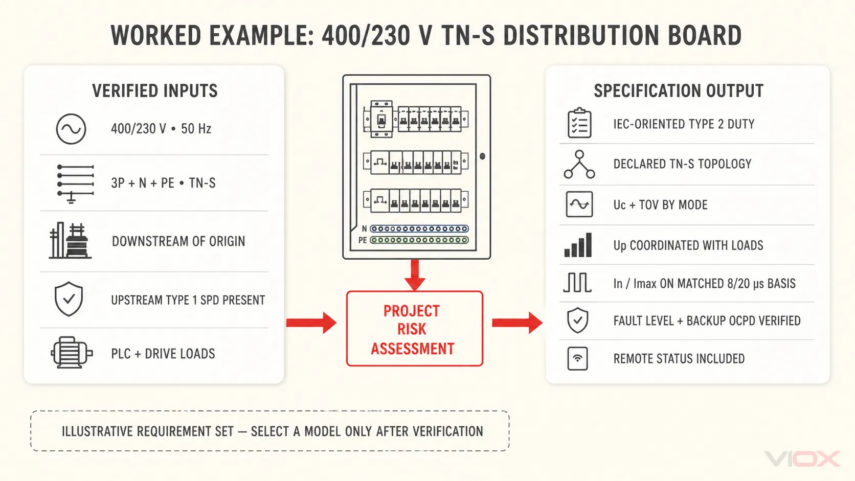
Praktický příklad: Rozváděč 400/230 V TN-S
Předpokládejme projekt, který eviduje rozváděč 400/230 V, 50 Hz, třífázový čtyřvodičový TN-S za přípojkou. Na začátku instalace je předřazené SPD typu 1, v tomto rozváděči není samostatné rozhraní pro přímý bleskový proud a následně je napájeno citlivé vybavení PLC a pohonů.
Správný výsledek není vymyšlený katalogový model. Je to soubor požadavků:
- Provozní třída typu 2 dle IEC na této úrovni rozvodu v závislosti na posouzení rizik projektu.
- Topologie schválena pro 3P+N TN-S s deklarovanými přesnými režimy L-N/N-PE nebo jinými požadovanými režimy.
- Hodnota Uc zvolena z tabulky výrobce pro TN-S na základě skutečného napětí v každém režimu a maximálních normálních podmínek.
- Chování při TOV kompatibilní se soustavou a místními předpisy.
- Hodnota Up koordinována s odolností následného zařízení a upravena pro zamýšlené uspořádání přívodních vodičů.
- Hodnoty In a Imax, pokud jsou deklarovány, zvoleny na základě požadavků projektu na rázové zatížení při shodném průběhu 8/20 µs.
- Dostupný zkratový proud ověřen vzhledem k SCCR/Isccr a tabulce záložní ochrany výrobce.
- Dálková signalizace zahrnuta, protože rozváděč je udržován centrálně.
Teprve po úplném splnění těchto podmínek by měl být vybrán konkrétní model.
Pracovní list pro poptávku (RFQ) třífázových SPD připravený ke kopírování
Aplikace / rozváděč:
Normativní rámec a trh:
Jmenovité napětí: ____ V L-L / ____ V L-N
Maximální normální napětí a frekvence:
Vodiče: L1 / L2 / L3 / N / PE nebo PEN
Soustava uzemnění a místo oddělení bond/PEN:
Rozhraní instalace a předřazený SPD:
Externí LPS / výsledek rizika úderu blesku:
Požadovaný typ SPD:
Požadovaná topologie a ochranné režimy:
Uc / MCOV podle režimu:
Požadované chování při TOV:
Maximální přípustné Up podle režimu:
Požadavek na Iimp s vlnovým průběhem a na pól/celkově:
Požadavek na In s vlnovým průběhem a režimem:
Požadavek na Imax, kde se používá, s vlnovým průběhem a režimem:
Prospektivní zkratový proud:
Požadovaná hodnota SCCR nebo příslušné prohlášení, jako je Isccr:
Předřazené ochranné zařízení:
Požadovaná externí záložní pojistka/jistič:
Montáž, prostředí a počet modulů:
Požadavek na vizuální / dálkovou signalizaci stavu:
Omezení vedení a poznámky ke koordinaci:
Požadované certifikáty a dokumentace:
Použijte průvodce technickým listem SPD pro ověření odpovědí dodavatele řádek po řádku. Následuje fyzická instalace dle průvodce zapojením SPD.
Pravidlo konečného výběru
Obhajitelná specifikace třífázového SPD musí projít každou kontrolou:
systémové napětí → uzemnění → typ instalace → topologie → Uc/TOV → Up → Iimp/In/Imax → ochrana proti poruchám/zálohování → vlastnosti projektu
Pokud cenová nabídka dodavatele postrádá ochranné režimy, testovací vlnové průběhy nebo koordinaci zkratové odolnosti, není zatím srovnatelná. Odešlete vyplněný pracovní list a jednopólové schéma na tým produktů VIOX SPD pro ověření na úrovni modelu.