
Why Understanding Low Voltage Fuse Standards Matters for Electrical Safety
When an electrical engineer specifies a “20A fuse” for a motor protection circuit, that three-character description represents dozens of critical technical decisions. Voltage rating, breaking capacity, time-current characteristics, physical dimensions, and utilization category all fundamentally affect whether that fuse will protect equipment reliably—or fail catastrophically during a fault condition.
At VIOX Electric, we manufacture low voltage fuses that comply with IEC 60269 international standards, serving panel builders, automation engineers, and electrical contractors across industrial, commercial, and renewable energy sectors. Through two decades of B2B partnerships, we’ve witnessed the costly consequences when procurement teams order fuses based solely on amperage ratings without understanding the classification system behind those numbers.
This comprehensive guide explains the IEC 60269 standard framework, decodes utilization categories (gG, aM, gPV, aR), and provides actionable selection criteria for matching fuse specifications to real-world applications. Whether you’re designing a new control panel, maintaining existing installations, or sourcing replacement components, this technical reference ensures you specify fuses correctly the first time.
IEC 60269: The Global Standard for Low Voltage Fuses
The International Electrotechnical Commission (IEC) standard 60269 provides the definitive technical specification for low voltage fuses used in electrical systems worldwide. First published in the 1980s and regularly updated (most recent edition: IEC 60269-1:2024), this multi-part standard harmonizes previously disparate national specifications from Germany (DIN VDE 0636), Britain (BS 88), France, and Italy.
Voltage and Current Scope
IEC 60269 applies to fuses with:
- AC voltage ratings: Up to 1,000V
- DC voltage ratings: Up to 1,500V
- Minimum breaking capacity: 6 kA (6,000 amperes)
- Current ratings: 2A to 1,250A (depending on physical size)
These voltage thresholds define “low voltage” in industrial electrical systems, distinguishing these fuses from medium-voltage (1kV-35kV) and high-voltage (>35kV) protection devices used in utility applications.
IEC 60269 Standard Structure
| Standard Part | Title | Application Scope |
|---|---|---|
| IEC 60269-1 | General Requirements | Common specifications for all fuse types: marking, dimensions, test procedures |
| IEC 60269-2 | Supplementary Requirements for Industrial Use | NH fuses, cylindrical fuses for qualified personnel (sizes A-I) |
| IEC 60269-3 | Supplementary Requirements for Domestic Use | Household fuses for unskilled persons (systems A-F) |
| IEC 60269-4 | Semiconductor Protection | aR-type fuses for thyristors, diodes, IGBTs |
| IEC 60269-6 | Photovoltaic Systems | gPV-type fuses rated 1,000-1,500V DC for solar applications |
For B2B electrical equipment manufacturers and panel builders, IEC 60269-2 represents the most relevant specification, covering HRC (High Rupturing Capacity) fuses used in industrial switchgear, motor control centers, and distribution boards.
Utilization Categories: Decoding the Two-Letter Code
Every IEC 60269 compliant fuse carries a two-letter utilization category marking that defines its intended application and operational characteristics. This classification system—often misunderstood outside specialist circles—directly determines whether a fuse will perform correctly in your specific circuit.
Classification System Structure
The two-letter code follows this format:
First letter (breaking range):
- g (german: “gesamt” = full): Full-range breaking capacity—protects against both overload and short-circuit currents
- a (german: “ausschließlich” = partial): Partial-range breaking capacity—protects only against short-circuit currents above a specified threshold
Second letter (application type):
- G: General purpose (cables, conductors, transformers)
- M: Motor circuits
- PV: Photovoltaic systems
- R: Semiconductor protection (rectifiers)
gG Fuses: General Purpose, Full-Range Protection
gG fuses (formerly designated gL in some national standards) represent the most common industrial fuse type, designed for comprehensive circuit protection.
Technical characteristics:
- Protects against both overload (1.6× rated current) and short-circuit conditions
- Conventional fusing current: 1.6× In (the current at which the fuse will melt within 1 hour)
- Breaking capacity: Typically 100-120 kA at rated voltage
- Time-current curve: Moderate speed—slower than semiconductor fuses, faster than motor protection types
Primary applications:
- Cable and conductor protection in distribution systems
- Transformer primary and secondary circuits
- General industrial power feeders
- Equipment with predictable, stable current draw
When specifying gG fuses, the rated current should not exceed 1.45 times the cable’s continuous current capacity to ensure proper overload protection under NEC/IEC installation codes.
aM Fuses: Motor Protection, Partial-Range
aM fuses are specifically engineered to accommodate the high inrush currents characteristic of motor starting while still providing robust short-circuit protection.
Technical characteristics:
- Withstands motor starting currents: 6-8× rated current without melting
- Partial-range protection: Only interrupts currents above approximately 5× In
- Breaking capacity: 100-120 kA (identical to gG at rated voltage)
- Time-current curve: Deliberately slower in overload region, comparable speed for short circuits
Primary applications:
- Three-phase induction motor circuits
- Power conversion equipment (VFDs, soft starters)
- Transformer inrush protection
- Any circuit with high surge currents during normal operation
Critical distinction: aM fuses do not provide overload protection for the motor windings. They must be used in conjunction with thermal overload relays (part of a motor starter assembly) that trip on sustained overcurrent before thermal damage occurs.
gPV Fuses: Photovoltaic System Protection
gPV fuses represent a specialized category developed specifically for DC solar applications, standardized in IEC 60269-6:2010.
Technical characteristics:
- Voltage ratings: 1,000V DC or 1,500V DC
- Designed for low-overload, high-short-circuit DC fault conditions
- Capable of interrupting reverse current faults (backfeed from parallel strings)
- Arc extinction optimized for DC applications
Primary applications:
- Solar combiner boxes (string protection)
- DC disconnect switches
- PV inverter input protection
The DC voltage ratings distinguish gPV fuses from standard AC-rated fuses, which cannot safely interrupt DC arcs due to the absence of current zero-crossing.
aR Fuses: High-Speed Semiconductor Protection
aR fuses (formerly called “ultra-rapid” or “rectifier” fuses) provide millisecond-level protection for sensitive power semiconductor devices.
Technical characteristics:
- Extremely fast operation: Clears faults in <5 milliseconds
- Very thin fuse element for rapid melting
- Partial-range: Does not protect against overload (relies on device thermal management)
- High I²t let-through values during normal operation (increased power dissipation)
Primary applications:
- Thyristor protection in power converters
- Diode and IGBT modules
- UPS systems
- Welding equipment

Utilization Category Comparison Table
| Category | Protection Range | Overload Response | Motor Starting | Breaking Capacity | Typical Application |
|---|---|---|---|---|---|
| gG | Full (overload + short-circuit) | Trips at 1.6× In | May nuisance trip | 100-120 kA | Cable protection, general circuits |
| aM | Partial (short-circuit only) | Withstands 6-8× In | Tolerates inrush | 100-120 kA | Motor circuits with thermal overload |
| gPV | Full (DC faults) | Trips at 1.6× In | N/A (DC systems) | 20-50 kA DC | Solar combiner boxes |
| aR | Partial (fast short-circuit) | No overload protection | N/A | 50-100 kA | Semiconductor devices |
Physical Fuse Sizes: NH and Cylindrical Standards
Understanding utilization categories solves only half the specification challenge. Physical dimensions must match the fuse base or holder installed in your electrical panel—incompatible sizes create procurement errors and installation delays.
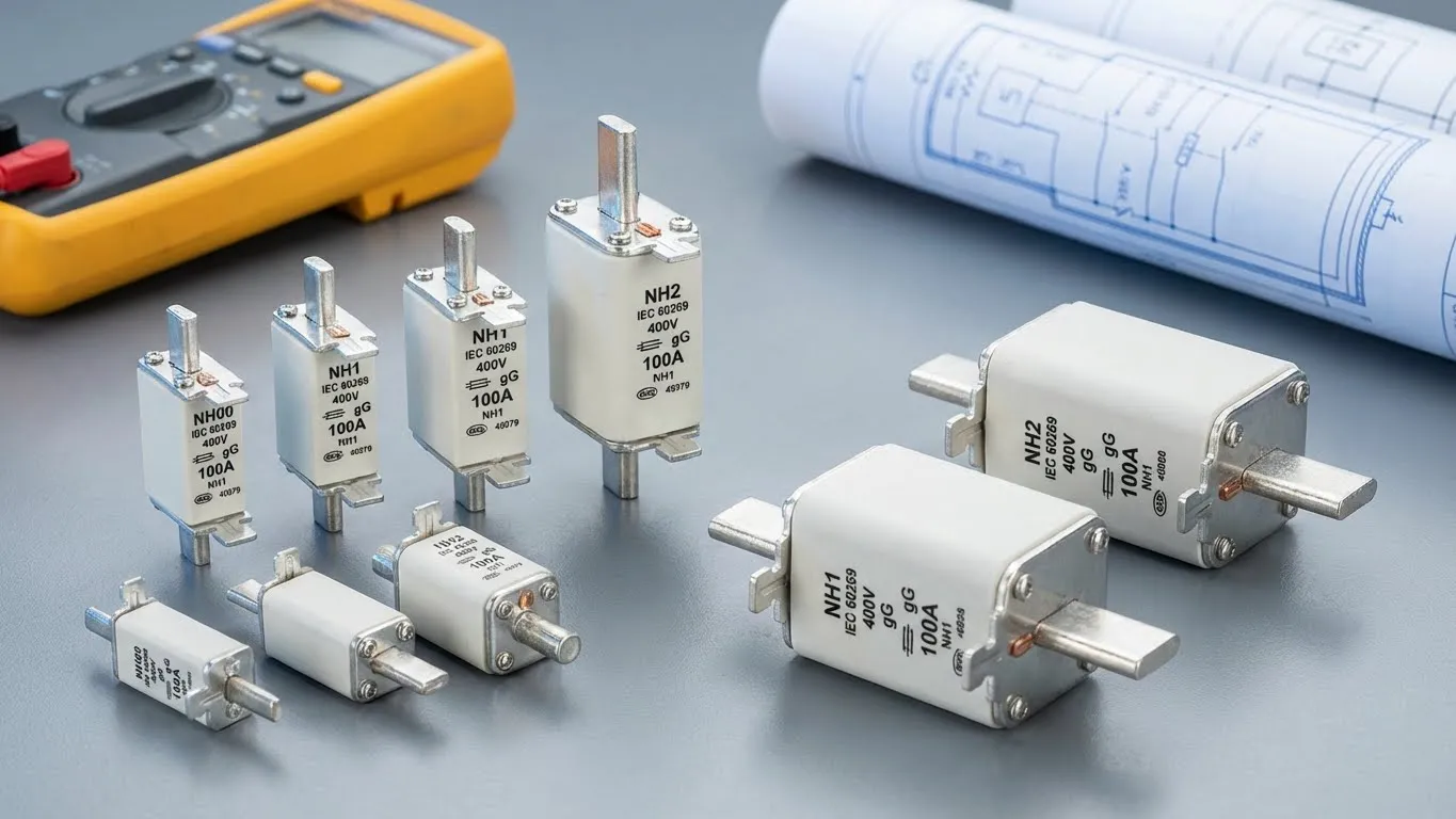
NH (Knife-Blade) Fuse Sizes
NH fuses—standardized in German DIN 43620 and incorporated into IEC 60269-2—represent the most common industrial fuse format worldwide. The “NH” designation derives from “Niederspannungs-Hochleistungs-Sicherungen” (low voltage, high power fuses).
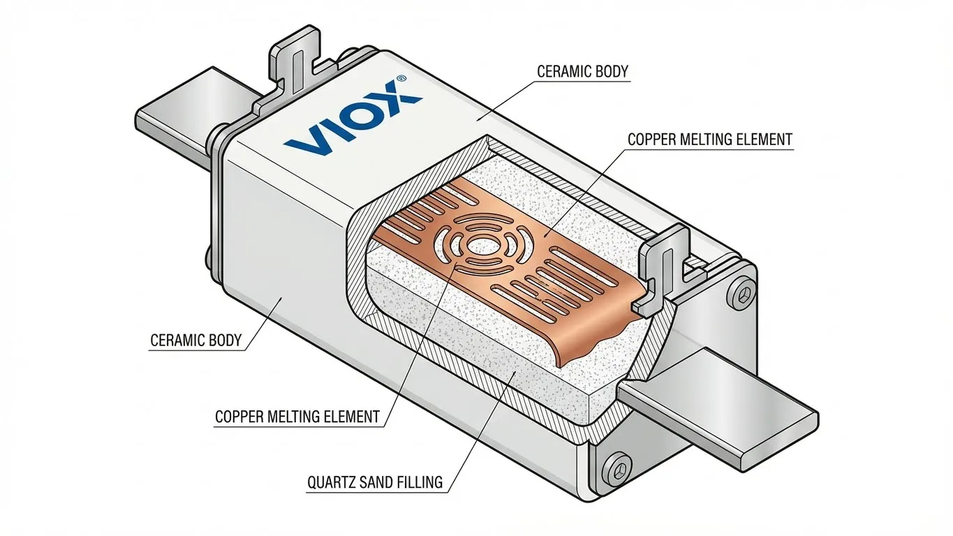
NH construction features:
- Ceramic body filled with quartz sand for arc extinction
- Silver-plated copper knife-blade terminals for low contact resistance
- Striker pin indicator (mechanical or with microswitch for remote monitoring)
- Color-coded handles for quick current rating identification
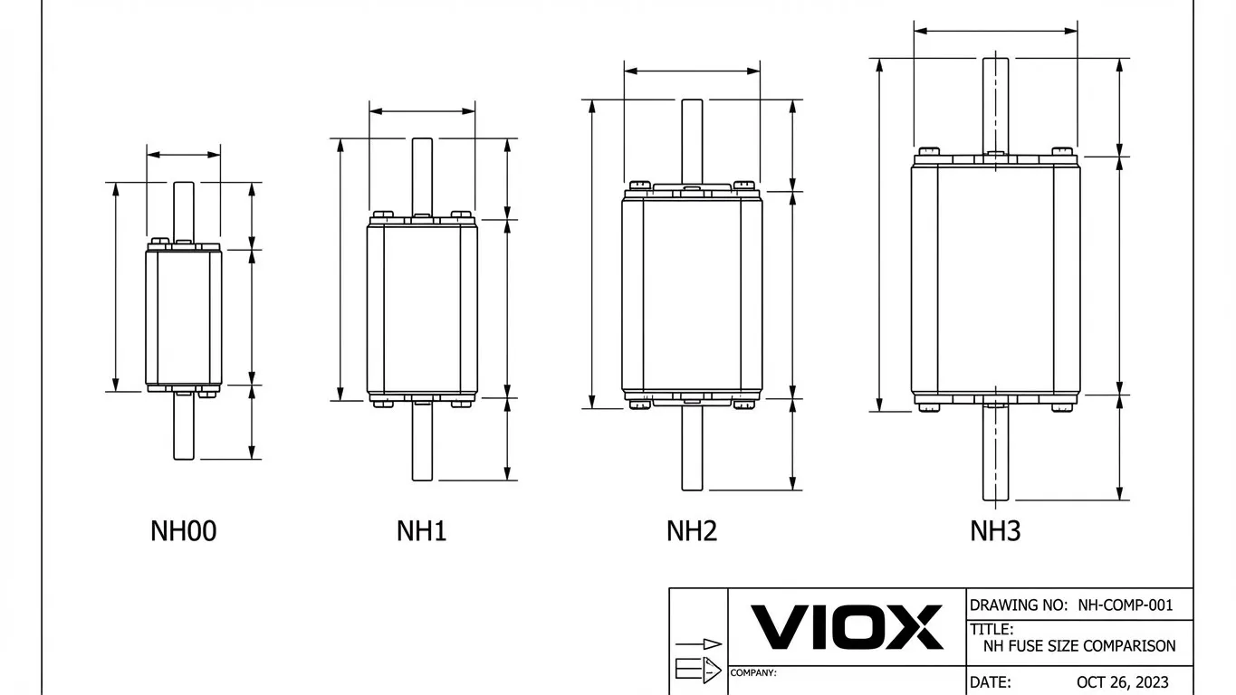
NH Size Specifications
| NH Size | Length (mm) | Width (mm) | Current Range (A) | Typical Breaking Capacity @ 500V | Applications |
|---|---|---|---|---|---|
| NH000 (or NH00C) | 185 | 65 | 2-160 | 120 kA | Control panels, small motors, sub-distribution |
| NH00 | 140 | 50 | 2-160 | 120 kA | Distribution boards, medium motors (up to 22kW) |
| NH0 | 95 | 45 | 4-100 | 120 kA | Smaller control panels, specialized applications |
| NH1 | 115 | 54 | 10-160 | 120 kA | Motor control centers, main distribution |
| NH2 | 150 | 69 | 125-250 | 120 kA | Industrial feeders, large motors (30-75kW) |
| NH3 | 215 | 100 | 200-630 | 120 kA | Main switchgear, transformer secondaries |
| NH4 | 330 | 155 | 500-1,250 | 80-100 kA | Service entrance, large industrial loads |
Important note: NH00 and NH000 sizes are often interchangeable in the same fuse base (designated “NH00C” or “Kombi” holders), but NH1-4 require size-specific bases. Always verify holder compatibility before ordering fuse links.
Cylindrical Fuse Sizes
Cylindrical fuses—following IEC 60269-2 standardized dimensions—serve control circuits, electronics, and applications requiring compact protection.
| Size Designation | Diameter × Length (mm) | Current Range (A) | Voltage Rating (AC) | Common Applications |
|---|---|---|---|---|
| 10×38 | 10 × 38 | 1-32 | 500-690V | PV string protection, control circuits, DC systems |
| 14×51 | 14 × 51 | 1-63 | 500-690V | Industrial control panels, power electronics |
| 22×58 | 22 × 58 | 1-125 | 500-690V | Medium power circuits, distribution boards |
These dimensions follow the international standardization that enables cross-manufacturer compatibility—any 14×51mm fuse link will physically fit any 14×51mm fuse holder, regardless of manufacturer (though electrical ratings must still match application requirements).
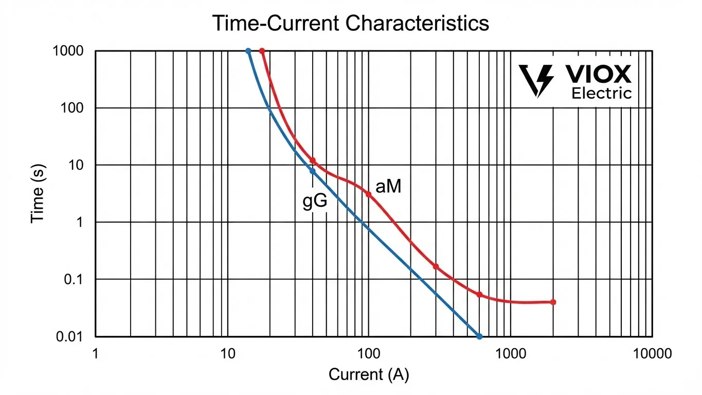
Time-Current Characteristics: Understanding Fuse Response
The time-current characteristic curve defines how quickly a fuse responds to different levels of overcurrent—a critical parameter for coordination with upstream and downstream protective devices.
gG Fuse Response Times (20A Example)
| Current Level | Multiplier | Expected Trip Time |
|---|---|---|
| 32A | 1.6× In | 1-2 hours (conventional fusing current) |
| 40A | 2× In | 2-5 minutes |
| 60A | 3× In | 30-60 seconds |
| 100A | 5× In | 2-5 seconds |
| 200A | 10× In | 0.1-0.2 seconds |
| 400A | 20× In | <0.01 seconds |
aM Fuse Response Times (20A Example)
| Current Level | Multiplier | Expected Trip Time |
|---|---|---|
| 32A | 1.6× In | No trip (designed tolerance) |
| 40A | 2× In | No trip |
| 60A | 3× In | 5-10 minutes |
| 100A | 5× In | 15-30 seconds |
| 200A | 10× In | 0.2-0.5 seconds |
| 400A | 20× In | <0.01 seconds (similar to gG) |
Critical observation: Notice that aM fuses intentionally do not respond to moderate overloads (2-4× rated current), accommodating motor starting inrush currents that would cause nuisance tripping with gG fuses. This tolerance window makes aM fuses unsuitable as standalone protection—they must work alongside thermal overload relays.
For detailed breaking capacity specifications and how they relate to high rupturing capacity (HRC) fuse design, refer to VIOX’s comprehensive guide on 300kA breaking capacity fuses.
Fuse Selection Guide: Matching Specifications to Applications
Proper fuse selection requires coordinating five critical parameters: utilization category, rated current, voltage rating, physical size, and breaking capacity.
Step-by-Step Selection Process
1. Identify the protected load type:
- Cables/conductors: Select gG category
- Motors: Select aM category (with thermal overload relay)
- Solar PV: Select gPV category
- Semiconductors: Select aR category
2. Calculate required fuse rating:
For gG fuses protecting cables:
Fuse rating = Cable ampacity ÷ 1.45
(Ensures fuse trips before cable overheats)
For aM fuses protecting motors:
Fuse rating = Motor full-load current × 1.5 to 2.0
(Accommodates starting inrush while protecting against locked rotor conditions)
For gPV fuses in solar systems:
Fuse rating = String short-circuit current × 1.56
(Per NEC 690.9 photovoltaic requirements)
3. Verify voltage rating:
- Fuse voltage rating must equal or exceed circuit nominal voltage
- For AC three-phase systems: Use line-to-line voltage (480V, 690V typical)
- For DC systems: Use maximum system voltage (1,000V or 1,500V for PV)
4. Confirm breaking capacity:
- Minimum 6 kA for IEC 60269 compliance
- Industrial systems typically require 50-120 kA depending on fault levels
- Consult short-circuit study data or use fault current calculators
5. Select physical size:
- NH sizes: Choose based on current rating and panel space availability
- Cylindrical: Select diameter × length matching existing holders
Common Application Examples
| Application | Utilization Category | Typical Size | Current Rating Guideline |
|---|---|---|---|
| 30kW motor (400V, 3-phase) | aM | NH2 | 80-100A (FLC ≈ 52A) |
| 25mm² copper cable | gG | NH1 | 50-63A (cable ampacity 89A) |
| 10-string solar array (8A/string) | gPV | 10×38mm | 16A per string |
| 50kW transformer secondary | gG | NH3 | 100-125A |
| VFD output circuit | aM | NH1 | Match motor FLC × 1.5 |
Interchangeability Rules
When you CAN substitute:
- ✅ gG → aM (less sensitive to overload, acceptable if thermal relay present)
- ✅ Lower breaking capacity → Higher breaking capacity (e.g., 50kA → 120kA)
- ✅ Higher voltage rating → Same voltage rating (e.g., 690V rated fuse in 480V system)
When you CANNOT substitute:
- ❌ aM → gG in motor circuits (will cause nuisance tripping)
- ❌ AC-rated → DC applications (arc extinction mechanisms differ)
- ❌ Higher current rating → Lower (defeats protection purpose)
- ❌ Lower breaking capacity → Required capacity (safety hazard)
Comparing fuse response characteristics with other protective devices, review VIOX’s analysis of fuse vs. MCB response times for applications requiring selectivity.
VIOX Electric: IEC 60269 Compliant Fuse Solutions
At VIOX Electric, we manufacture comprehensive low voltage fuse systems engineered to IEC 60269 standards for B2B customers across industrial automation, renewable energy, and commercial electrical sectors.
Product range:
- NH fuse links (sizes 000-4, gG and aM categories, 2-1,250A)
- Cylindrical fuse links (10×38mm, 14×51mm, 22×58mm formats)
- NH fuse bases and carriers (single and triple-pole configurations)
- gPV photovoltaic fuses (1,000V DC, 1,500V DC ratings)
All VIOX fuse products carry CE certification, IEC 60269 compliance verification, and undergo rigorous breaking capacity testing at 120 kA (NH series) and 50 kA (cylindrical series) to ensure reliable performance under fault conditions.
Frequently Asked Questions
What does gG mean on a fuse?
gG represents “general purpose, full-range” utilization category under IEC 60269. The first letter “g” (gesamt = full) indicates the fuse provides protection against both overload and short-circuit currents. The second letter “G” specifies general application for cables, conductors, and equipment. gG fuses will trip at 1.6 times their rated current within 1 hour and can safely interrupt currents up to their rated breaking capacity (typically 100-120 kA).
Can I replace a gG fuse with an aM fuse?
No, this substitution is unsafe in most applications. aM fuses do NOT provide overload protection—they only interrupt high-magnitude short-circuit faults. Using an aM fuse where a gG fuse is specified removes critical overload protection, potentially allowing cables or equipment to overheat before the fuse operates. The reverse substitution (gG in place of aM) is technically safe but may cause nuisance tripping in motor circuits due to starting inrush currents.
What NH fuse size do I need for a 200A circuit?
For a 200A rated current, select NH2 or NH3 size depending on application and voltage:
- NH2 size: Available in ratings up to 250A, suitable for 200A if space-constrained
- NH3 size: Preferred choice for 200A applications due to superior thermal performance and lower power dissipation
Always verify that your fuse base matches the physical size selected. NH2 and NH3 are not interchangeable without changing the fuse holder.
How do I identify if a fuse is IEC 60269 compliant?
IEC 60269 compliant fuses must display the following markings directly on the fuse body:
- Utilization category (gG, aM, gPV, etc.)
- Rated current (e.g., 63A)
- Rated voltage (e.g., 500V AC)
- Breaking capacity (e.g., 120kA)
- Manufacturer identification
Additionally, look for CE marking and IEC 60269-2 (industrial) or IEC 60269-3 (household) standard reference. Fuses without these clear markings may not meet international safety requirements.
What is the difference between NH and BS88 fuses?
NH fuses (German DIN 43620 standard) and BS88 fuses (British Standard) are both covered under IEC 60269 but have different physical dimensions. NH fuses use knife-blade contacts and are sized by designations 000, 00, 1, 2, 3, 4. BS88 fuses use rectangular bolt-on or clip-in mounting and are sized by catalog numbers (e.g., 00, 1, 2, 3, 4). While both meet IEC electrical requirements, they are not mechanically interchangeable—the fuse base must match the fuse link standard.
Why can’t I use an AC-rated fuse in a DC circuit?
AC fuses rely on the natural current zero-crossing that occurs 100-120 times per second (depending on 50Hz/60Hz frequency) to extinguish the arc when interrupting a circuit. DC current has no zero-crossing—the arc persists continuously, requiring different arc-quenching mechanisms and extended contact gaps. Using an AC-rated fuse in a DC circuit can result in the fuse failing to interrupt the fault, potentially causing fire or equipment damage. Always use DC-rated fuses (like gPV) for DC applications, especially photovoltaic systems.
Conclusion: Specification Precision Ensures System Safety
Understanding IEC 60269 standards, utilization categories (gG, aM, gPV, aR), and physical sizing requirements transforms fuse selection from guesswork into engineering precision. Whether you’re designing new electrical systems, maintaining existing installations, or procuring replacement components, these technical specifications ensure compatibility, compliance, and reliable overcurrent protection.
Key takeaways:
- IEC 60269 unifies global low voltage fuse standards (up to 1,000V AC, 1,500V DC)
- Utilization categories define application-specific protection characteristics
- gG provides full-range protection; aM tolerates motor inrush; gPV handles DC faults
- Physical sizes (NH 000-4, cylindrical formats) must match installed fuse bases
- Never substitute fuse types without verifying electrical and mechanical compatibility
VIOX Electric manufactures IEC 60269 compliant fuse solutions backed by technical support, application engineering, and global B2B partnerships. For specification assistance, product catalogs, or custom fuse system design, contact our technical team to ensure your overcurrent protection meets both safety requirements and operational demands.
