¿Qué tan rápido conmuta realmente un interruptor de transferencia automática?
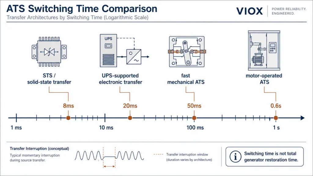
El tiempo de conmutación del ATS es el intervalo de transición durante el cual la carga se transfiere de una fuente de energía a otra. En sistemas prácticos, puede variar desde una transferencia de subciclo en arquitecturas de interruptores de transferencia estática (STS) hasta cientos de milisegundos en interruptores de transferencia automática mecánicos convencionales. Este tiempo de conmutación a nivel de dispositivo no es lo mismo que el tiempo total de restauración, que puede incluir la detección de la fuente, el arranque del generador, el calentamiento, el retardo de transferencia y la lógica de retransferencia.
Cuando los ingenieros comparan 8ms, 20ms, 50ms o 0.6s las afirmaciones sobre la velocidad de transferencia, no siempre están comparando el mismo tipo de dispositivo. Una transferencia de 8ms generalmente apunta a una conmutación de estado sólido o respaldada por UPS. Una transferencia de 0.6s generalmente apunta a un interruptor de transferencia operado por motor o accionado mecánicamente. Ambos pueden ser correctos en la aplicación adecuada.
La verdadera pregunta no es “¿qué ATS es el más rápido?”, sino más bien:
¿Cuánto tiempo puede tolerar la carga conectada una interrupción de tensión y qué arquitectura de transferencia se necesita para mantenerse dentro de ese límite?
Si primero necesita el significado básico del dispositivo, comience por Significado de ATS en electricidad. Si está comparando la transferencia de fuente automática y manual, consulte Conmutador de transferencia manual frente a automático.
Puntos Clave
- El tiempo de conmutación no es el tiempo total de respaldo. La cifra de 8 ms a 0,6 s generalmente describe el intervalo de transición de la fuente, no el tiempo total necesario para que un generador arranque y se estabilice.
- La transferencia de subciclo pertenece a arquitecturas STS o de transferencia electrónica. Los mecanismos ATS mecánicos convencionales normalmente no están diseñados para una transferencia real de 8 ms.
- 20 ms es un punto de referencia común de tolerancia (ride-through) para muchas fuentes de alimentación de TI, pero no es una garantía universal. La tolerancia real depende del diseño del equipo, el nivel de carga, el voltaje de entrada y el estado de la fuente de alimentación.
- 50 ms es rápido para un dispositivo de transferencia mecánica, pero sigue siendo una interrupción y puede reiniciar PLC, contactores, variadores o equipos de TI sin soporte de tolerancia (ride-through).
- 0.6 s es aceptable en muchas aplicaciones de generadores, iluminación, HVAC, bombas y distribución general, pero no es adecuado para cargas que requieren energía sin interrupción o casi sin interrupción, a menos que se utilice UPS, STS o almacenamiento de energía.
- Más rápido no es automáticamente mejor. Los motores, transformadores y variadores pueden requerir una transición retardada, una transferencia en fase o una gestión de tensión residual.
- Las normas y la clasificación del proyecto son importantes. La norma IEC 60947-6-1, UL 1008, NFPA 110, NEC artículos 700/701, los códigos locales y la autoridad competente pueden afectar la especificación final.
Comparativa de las cuatro velocidades de conmutación de los ATS
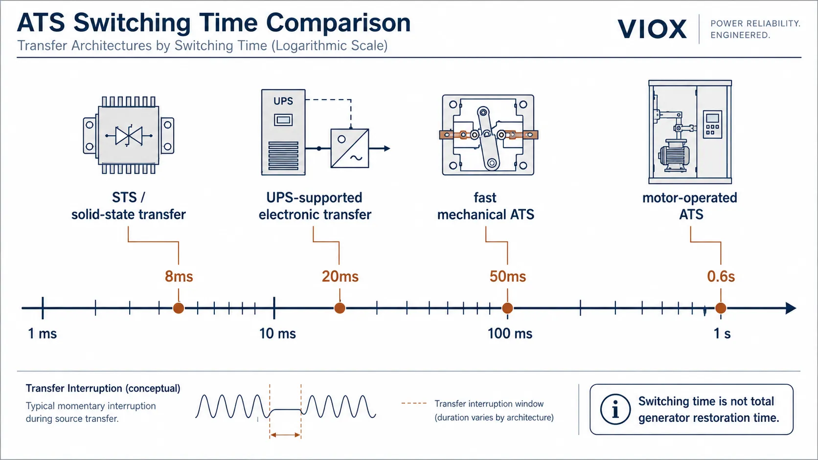
Cada velocidad principal corresponde a una arquitectura de conmutación diferente. El mecanismo, la disponibilidad de la fuente y la capacidad de tolerancia a fallos de la carga son tan importantes como el número impreso en la hoja de datos.
| Velocidad de conmutación | Ciclos aprox. a 50 Hz / 60 Hz | Arquitectura de conmutación típica | Cargas más adecuadas | Advertencia principal |
|---|---|---|---|---|
| ≤8ms | ≤0.4 / ≤0.48 ciclos | Conmutador de transferencia estática, bypass de SAI, transferencia electrónica | Servidores, almacenamiento, telecomunicaciones, TI crítica de subciclo | Generalmente no es un ATS mecánico convencional |
| ~20ms | ~1 / ~1.2 ciclos | STS, transferencia soportada por UPS, arquitectura de transferencia rápida premium | Equipos de TI con capacidad de tolerancia a fallos verificada, rectificadores de telecomunicaciones, controles con tiempo de retención | No asuma que todos los componentes electrónicos sobreviven a 20ms |
| ~50ms | ~2.5 / ~3 ciclos | ATS mecánico rápido, transferencia basada en contactores, transferencia clase PC | Electrónica general, iluminación, muchas cargas auxiliares industriales | Todavía no es una transferencia sin interrupción (no-break) |
| ~0.6s | ~30 / ~36 ciclos | ATS operado por motor, interruptor de transferencia de doble potencia estándar, clase CB o transferencia mecánica | Iluminación, HVAC, bombas, ventiladores, distribución no crítica respaldada por generador | Demasiado lento para cargas de TI a menos que estén respaldadas por UPS |
A 50 Hz, un ciclo de CA es 20 ms. A 60 Hz, un ciclo es de aproximadamente 16.7 ms. Es por esto que las discusiones sobre la velocidad de transferencia a menudo utilizan tanto milisegundos como ciclos de potencia.
El tiempo de transición no es el tiempo total de transferencia
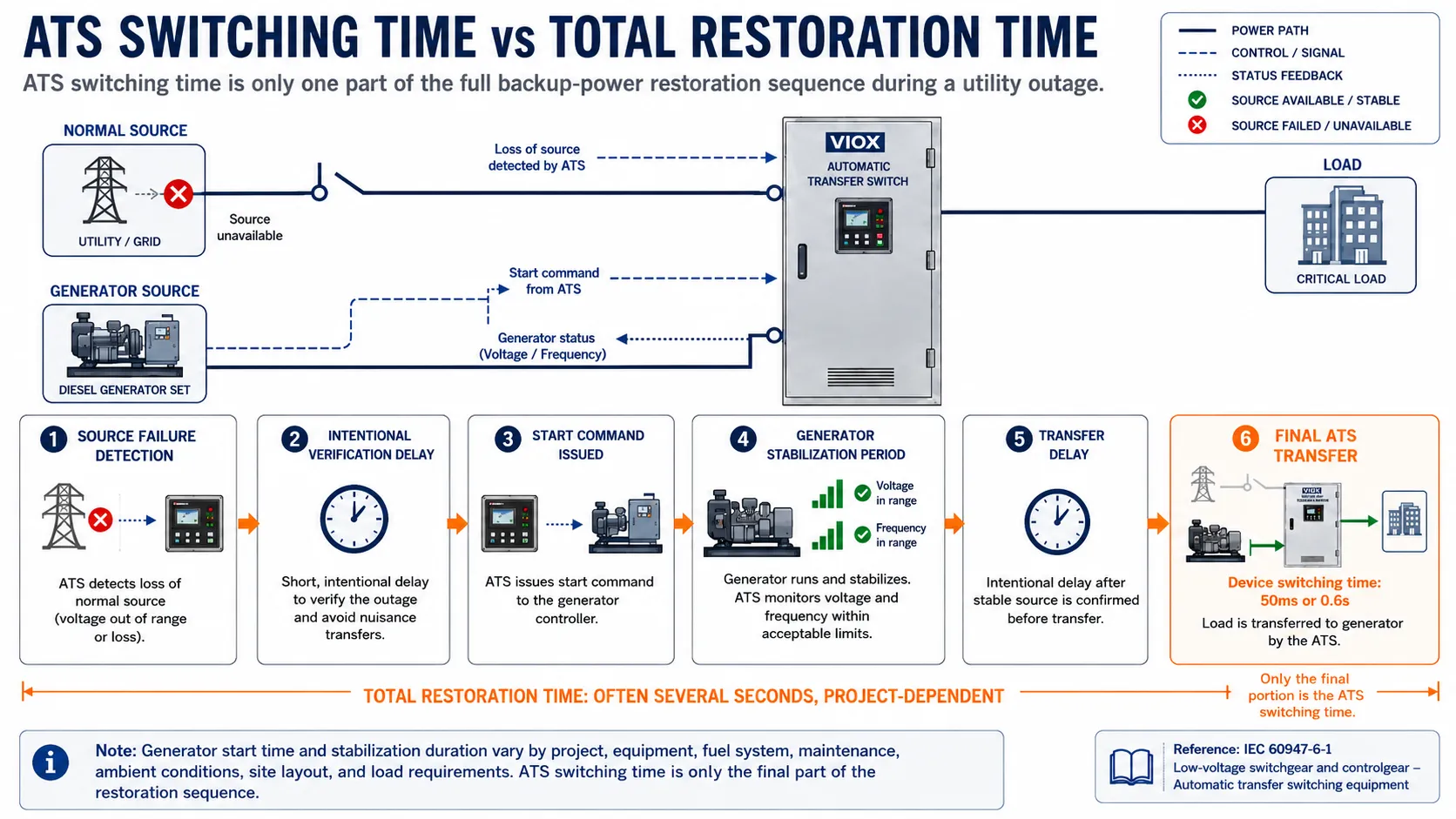
Este es el error de especificación más común en proyectos de ATS.
El número en milisegundos en la hoja de datos de un dispositivo generalmente describe el intervalo de conmutación o transición. Una transferencia completa de red a generador puede incluir:
- Detección de falla de la fuente de red.
- Retraso de confirmación intencional para evitar transferencias molestas.
- Comando de arranque del generador.
- Giro y arranque del motor.
- Estabilización de voltaje y frecuencia del generador.
- Retraso de transferencia programado.
- Transferencia mecánica o electrónica a la fuente alternativa.
Esto significa que un sistema con un mecanismo de conmutación rápida de 50 ms aún puede dejar la carga sin energía del generador durante varios segundos durante un corte real de la red eléctrica. El ATS no “tardó varios segundos en conmutar”; la fuente alternativa aún no estaba lista.
En la práctica de energía de emergencia de América del Norte, las clasificaciones de tipo de sistema NFPA 110 y los requisitos de emergencia/espera del NEC a menudo se centran en el tiempo total de restauración en lugar de solo en el tiempo de movimiento de los contactos. Por ejemplo, los sistemas de suministro de energía de emergencia Tipo 10 están asociados con expectativas de restauración de 10 segundos, mientras que los sistemas de espera legalmente requeridos pueden tener diferentes ventanas de tiempo según la edición del código y la aplicación. Verifique siempre el requisito exacto con el código vigente, la especificación del proyecto y la autoridad competente.
La clasificación en milisegundos se vuelve más decisiva cuando ambas fuentes ya están disponibles, tales como:
- transferencia de red eléctrica a red eléctrica
- transferencia de bypass de UPS
- selección de fuente STS
- rutas de alimentación de doble entrada para centros de datos
- transferencia aguas abajo de una fuente alternativa que ya está en funcionamiento
En esos casos, el intervalo de transición puede ser cercano a la interrupción real que experimenta la carga.
Transferencia de 8 ms: Generalmente conmutación a nivel de STS o UPS
Una transferencia de 8 ms es extremadamente rápida. Es aproximadamente medio ciclo a 60 Hz y menos de medio ciclo a 50 Hz.
Esta velocidad se asocia habitualmente con:
- conmutadores de transferencia estática que utilizan SCR o tiristores
- sistemas de bypass de UPS
- sistemas de alimentación IT de doble fuente
- arquitecturas de alimentación para telecomunicaciones
- sistemas de transferencia electrónica donde ambas fuentes ya son aceptables
Los mecanismos de ATS mecánicos convencionales normalmente no están diseñados para transferencias sub-ciclo. Contienen contactos móviles, varillajes, enclavamientos, motores o mecanismos de contactores, y esas piezas requieren un tiempo de desplazamiento físico.
Cuando 8ms tiene sentido
Una arquitectura de transferencia de clase 8ms tiene sentido cuando la carga no puede tolerar ni siquiera una breve interrupción mecánica:
- servidores de centros de datos
- sistemas de almacenamiento
- equipo de telecomunicaciones
- conmutadores de red
- sistemas de control con muy baja tolerancia a fallos de tensión
- equipos electrónicos médicos o de laboratorio que requieren continuidad de potencia
- equipos de proceso donde un reinicio provoca un tiempo de inactividad importante
Pero un dispositivo de transferencia de 8 ms aún requiere dos fuentes aceptables disponibles en el momento de la transferencia. Si la fuente alternativa es un generador de reserva que no ha arrancado, el sistema no puede restaurar la carga en 8 ms sin un SAI, almacenamiento en baterías, respaldo de CC u otra capa de continuidad.
Para el límite entre ATS y STS, véase Interruptor de Transferencia Automática ATS vs Interruptor de Transferencia Estática STS.
Transferencia de 20 ms: Territorio de un ciclo
A 50 Hz, 20 ms equivalen a un ciclo completo de CA. A 60 Hz, es ligeramente superior a un ciclo.
Este punto de referencia es importante porque muchas fuentes de alimentación de tecnología de la información tienen una capacidad de continuidad limitada. La curva ITIC/CBEMA se cita a menudo al discutir la tolerancia de los equipos informáticos a las interrupciones breves de tensión. Sin embargo, no debe considerarse como una garantía universal de que cada ordenador, PLC, servidor o dispositivo de control sobrevivirá a cada evento de transferencia de 20 ms.
La continuidad real depende de:
- voltaje de entrada antes de la interrupción
- porcentaje de carga
- diseño de la fuente de alimentación
- estado del enlace de CC o del condensador
- antigüedad del equipo
- si varios dispositivos se reinician simultáneamente
- si el dispositivo tiene lógica de disparo por subtensión
Dónde puede funcionar 20ms
Un rango de transferencia de 20 ms puede ser aceptable para:
- Equipos informáticos con retención de fuente de alimentación verificada
- Sistemas de entrada de rectificadores de telecomunicaciones
- Electrónica de control con capacidad de tolerancia a fallos (ride-through)
- Cargas respaldadas por SAI (UPS)
- Equipos electrónicos de baja potencia donde una interrupción momentánea es aceptable
El riesgo
La suposición arriesgada es: “20 ms es lo suficientemente rápido para la electrónica.”
A veces lo es, a veces no. La fuente de alimentación de un PLC, la bobina de un contactor, el circuito de control de un variador de frecuencia (VFD), un relé de seguridad o un controlador embebido pueden comportarse de manera diferente a la fuente de alimentación de un servidor. Para sistemas críticos, la respuesta debe provenir de las especificaciones del equipo, las pruebas de puesta en marcha o las pruebas de aceptación en sitio.
Transferencia de 50 ms: ATS mecánico rápido, pero sigue siendo una interrupción.
Una transferencia de 50 ms es rápida para un dispositivo de conmutación mecánica. Equivale a unos 2.5 ciclos a 50 Hz o 3 ciclos a 60 Hz.
Este rango puede ser adecuado para:
- circuitos de iluminación
- distribución comercial general
- muchas cargas de motores
- Paneles de control HVAC
- paneles de bombeo
- cargas auxiliares industriales
- cuadros de distribución no informáticos respaldados por generador
- paneles de control con fuentes de alimentación de respaldo verificadas
Sin embargo, 50 ms no es una interrupción cero. Algunas cargas lo soportarán. Otras pueden reiniciarse, desconectarse, dispararse o activar alarmas.
Cargas que pueden reaccionar negativamente a 50 ms
Tenga cuidado con:
- PLC sin fuentes de alimentación de respaldo
- bobinas de contactores para circuitos críticos
- variadores de frecuencia con ajustes de disparo por subtensión
- controladores de proceso
- relés de seguridad
- sistemas de seguridad
- equipos informáticos sin SAI
- equipos electrónicos médicos
Si la pérdida de carga es inaceptable, utilice soporte de SAI, arquitectura STS, transferencia de transición cerrada cuando sea adecuado o sistemas de mantenimiento de energía de control local.
Transferencia de 0.6s: Normal para muchas aplicaciones de ATS mecánicos
Un Transferencia de 0.6s es mucho más lenta que 8ms, 20ms o 50ms, pero no significa automáticamente un bajo rendimiento. Pertenece a una categoría de aplicación diferente.
Para muchos interruptores de transferencia automática operados por motor e interruptores de transferencia de doble potencia, un tiempo de transferencia de cientos de milisegundos es aceptable porque las cargas conectadas pueden tolerar una breve interrupción de energía.
Las aplicaciones más comunes son:
- sistemas de generadores de reserva
- paneles de distribución no críticos
- bombas y ventiladores
- circuitos de iluminación
- Los sistemas HVAC
- equipos agrícolas
- cuadros industriales pequeños
- circuitos de respaldo residenciales o comerciales
En estos sistemas, el factor de interrupción más importante a menudo no es la acción de conmutación de 0,6 s. Es la secuencia de arranque y estabilización del generador.
Cómo el mecanismo de conmutación determina la velocidad
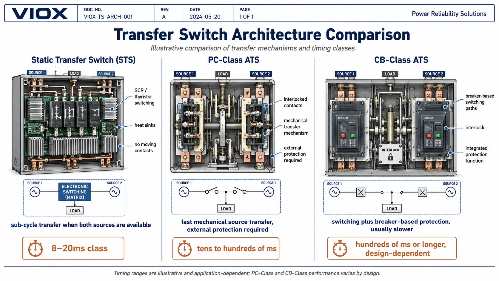
La velocidad, la protección y la resistencia están determinadas por el elemento de conmutación. En la terminología de conmutación de transferencia de la IEC, el equipo de conmutación de transferencia puede analizarse en relación con Clase de PC y clase CB dispositivos bajo la norma IEC 60947-6-1. En aplicaciones norteamericanas, el equipo de conmutación de transferencia se evalúa comúnmente bajo UL 1008.
| Atributo | Interruptor de transferencia estática (STS) | ATS de clase PC | ATS de clase CB |
|---|---|---|---|
| Elemento de conmutación | Trayectoria de SCR / tiristor / semiconductor | Contactos, contactores o mecanismo de conmutación sin protección de disparo integrada | Trayectoria de conmutación basada en interruptor automático |
| Rango de transferencia típico | De subciclo a un ciclo cuando las fuentes están disponibles | De decenas a cientos de milisegundos dependiendo del diseño | A menudo cientos de milisegundos o más |
| Contactos de potencia móviles | No | Sí | Sí |
| Protección contra sobrecorriente integrada | No; se requiere protección externa | No; se requiere protección externa | Sí, dependiendo del diseño |
| Mejor opción | Transferencia crítica de TI y telecomunicaciones entre fuentes activas | Transferencia de fuente de alta resistencia | Alimentadores que requieren conmutación además de protección basada en interruptores automáticos |
| Principal compromiso | Transferencia más rápida, mayor integración del sistema | Transferencia mecánica rápida de fuente | Integración de protección, mecanismo a menudo más lento |
La implicación práctica: la velocidad y la protección son ejes de diseño diferentes. Un ATS de clase PC rápido puede seguir necesitando protección aguas arriba o aguas abajo. Un ATS de clase CB puede integrar protección pero transferir más lentamente. Un STS puede transferir muy rápidamente, pero no pertenece a la misma categoría de producto que un ATS para generador.
Para un contexto de selección más detallado, consulte Guía de selección de ATS de clase PC vs. clase CB y Guía de selección de ATS de transición abierta vs. cerrada.
Transición abierta, transición retardada, transición cerrada y transferencia estática
La velocidad de transferencia también depende del método de transición.
| Tipo de transferencia | Cómo funciona | Perfil de interrupción | El Uso Típico |
|---|---|---|---|
| ATS de transición abierta | Desconexión de una fuente antes de la conexión a la otra | Interrupción definida | La mayoría de los sistemas de transferencia de generadores |
| ATS de transición retardada | Añade un tiempo intencional de neutro/apagado entre fuentes | Interrupción controlada más larga | Motores, transformadores, decaimiento de tensión residual |
| ATS de transición cerrada | Paralela momentáneamente dos fuentes sincronizadas aceptables | Poca o ninguna interrupción durante la transferencia planificada | Pruebas, retransferencia, instalaciones críticas |
| Conmutador de transferencia estática (STS) | Utiliza conmutación por semiconductores entre dos fuentes disponibles | Transferencia muy rápida, a menudo inferior a un ciclo | Centros de datos, telecomunicaciones, electrónica crítica |
La transición cerrada puede reducir la interrupción durante la transferencia o retransferencia planificada cuando ambas fuentes están presentes, son aceptables y están sincronizadas. No es una solución mágica sin interrupción durante un fallo total de la fuente. Si la fuente normal desaparece y la fuente alternativa no está disponible, otra fuente de respaldo debe soportar la carga.
Elección de la velocidad de conmutación adecuada para su aplicación
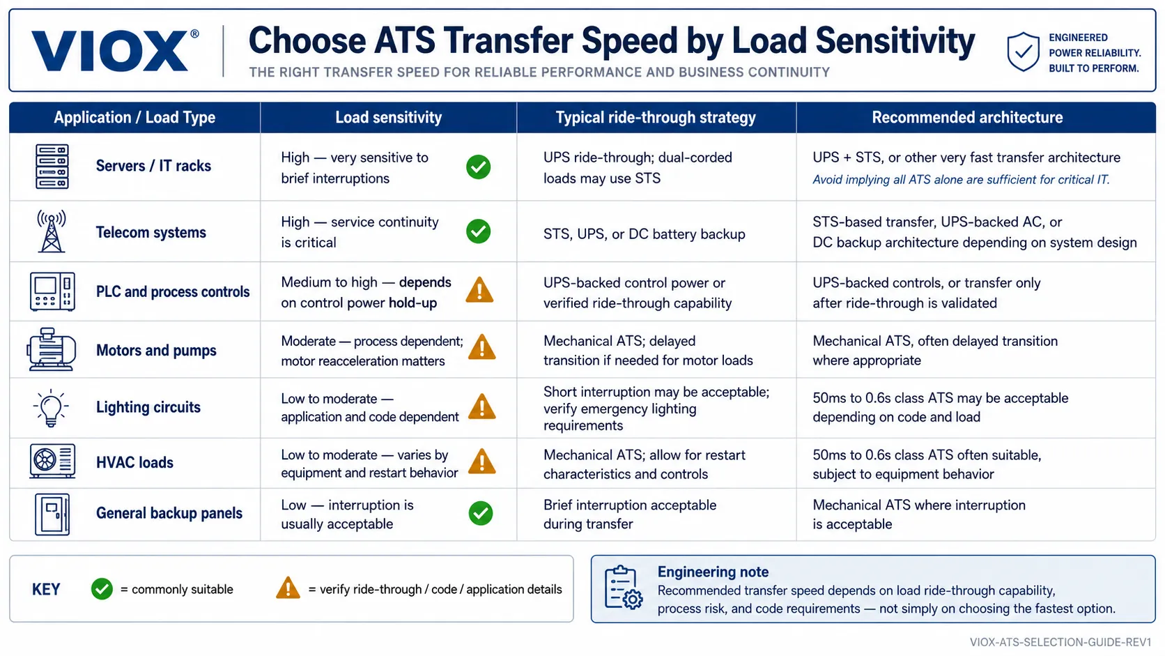
Ajuste la velocidad de transferencia a la sensibilidad de la carga, no al número más bajo del catálogo.
| Aplicación | Estrategia de velocidad de transferencia | Arquitectura típica |
|---|---|---|
| Bus de TI de centro de datos | Transferencia de subciclo o de un ciclo | STS aguas abajo de rutas de UPS duales o de red eléctrica dual |
| Central telefónica | Transferencia muy rápida más capacidad de compensación de CC (ride-through) | STS, UPS, planta de CC o diseño de rectificador redundante |
| PLC y control de procesos | La capacidad de respuesta (ride-through) para la alimentación de control suele ser más importante que la velocidad del ATS | Alimentación de control respaldada por UPS o retención de CC verificada |
| Cargas de seguridad vital en hospitales | Seguir los requisitos de restauración definidos por el código | Generador más ATS diseñados según el estándar del proyecto |
| Motores y bombas | Los ATS mecánicos pueden ser aceptables; la transición retardada puede ser beneficiosa | ATS de clase PC o clase CB con coordinación de rearranque de motor |
| Energía de respaldo comercial | Cientos de milisegundos a varios segundos pueden ser aceptables | ATS motorizado o interruptor de transferencia de doble potencia |
| Respaldo residencial o híbrido solar | Depende del inversor, la batería, el generador y la tolerancia de la carga | ATS rápido, transferencia por inversor o UPS para cargas sensibles |
Para TI de misión crítica, la arquitectura es más importante que un número único de ATS. Un UPS cubre el intervalo mientras arranca un generador, y un STS o sistema de transferencia electrónica gestiona la selección entre fuentes activas. Para sistemas de respaldo con generador, el movimiento de conmutación en fracciones de segundo puede ser menos importante que la detección de la fuente, la fiabilidad del arranque del generador y la clasificación correcta de la carga.
Lista de verificación de especificaciones prácticas
Antes de especificar el tiempo de conmutación del ATS, confirme:
- ¿Cuál es el tipo de carga: TI, motor, iluminación, control, médico, proceso, HVAC o distribución general?
- ¿La fuente alternativa ya está disponible o necesita arrancar?
- ¿El valor de la hoja de datos se refiere al tiempo de transición, tiempo de transferencia mecánica, tiempo de interrupción de carga o tiempo total de restauración?
- ¿La transferencia es abierta, retardada, cerrada o estática?
- ¿Puede la carga soportar la interrupción declarada?
- ¿Se requiere UPS, respaldo de CC o capacidad de mantenimiento de energía de control (ride-through)?
- ¿Se requiere sincronización de fuentes y aprobación de la compañía eléctrica para la transición cerrada?
- ¿El dispositivo es de clase PC, clase CB, STS, transferencia por inversor u otra arquitectura?
- ¿El proyecto requiere IEC 60947-6-1, UL 1008, NFPA 110, NEC Artículo 700/701 u otra norma local?
- ¿Se verificará el comportamiento de la transferencia durante la puesta en marcha?
Para la lógica de pruebas en sitio y puesta en marcha, consulte Cómo probar un interruptor de transferencia automática de forma segura.
Errores comunes de selección
Error 1: Comparar un STS de 8 ms con un ATS de 0.6 s como si fueran el mismo dispositivo
Un STS y un ATS mecánico resuelven problemas diferentes. Un STS realiza la transferencia muy rápidamente entre fuentes vivas aceptables. Un ATS mecánico se utiliza a menudo para gestionar la transferencia de energía respaldada por generador de forma segura y económica.
Error 2: Confundir el tiempo de conmutación con el tiempo total de interrupción
Un ATS de 50 ms no significa que la carga se restablezca en 50 ms tras un fallo de la red eléctrica si la fuente alternativa es un generador. El arranque y la estabilización del generador dominan la interrupción.
Error 3: Asumir que una transferencia más rápida es siempre mejor
Algunas cargas se benefician de una transición retardada. Los motores, transformadores y variadores pueden necesitar que la tensión residual decaiga antes de la reconexión. La transferencia rápida puede ser útil, pero no es universalmente correcta.
Error 4: Ignorar la sincronización de las fuentes
La transición cerrada requiere una relación aceptable de tensión, frecuencia y fase entre las fuentes. Sin sincronización y aprobación, poner fuentes en paralelo puede crear un riesgo grave para el sistema.
Error 5: Seleccionar la velocidad del ATS sin realizar pruebas de carga
Si la carga es crítica, no confíe únicamente en el valor del catálogo. Confirme la tolerancia de paso (ride-through), pruebe el comportamiento de la transferencia durante la puesta en marcha y documente los resultados aceptables.
PREGUNTAS FRECUENTES
¿Qué es el tiempo de conmutación de un ATS?
El tiempo de conmutación de un ATS es el tiempo que tarda el dispositivo de transferencia en cambiar la conexión de la carga de una fuente a otra después de la orden de transferencia. Puede no incluir la detección de la fuente, el retardo programado, el arranque del generador, la estabilización de la fuente o la lógica de retransferencia.
¿Es realista un tiempo de conmutación de 8 ms en un ATS?
8 ms es realista para conmutadores de transferencia estáticos (STS), sistemas de bypass de UPS y arquitecturas de transferencia electrónica. Por lo general, no es realista para un ATS mecánico convencional con contactos de potencia móviles.
¿Puede un ATS mecánico realizar una transferencia en 8 ms?
Los dispositivos ATS mecánicos convencionales normalmente no están diseñados para transferencias de menos de un ciclo. Si una hoja de datos indica 8 ms, verifique si el dispositivo es en realidad un STS, un sistema de transferencia electrónica híbrido, un bypass de UPS u otra arquitectura.
¿Es 20 ms lo suficientemente rápido para las computadoras?
A veces, pero no siempre. Muchas fuentes de alimentación de TI pueden soportar interrupciones breves, pero la tolerancia depende del diseño de la fuente de alimentación, el nivel de carga, el voltaje de entrada, el estado de los condensadores y si existe respaldo de un UPS.
¿Se considera rápido un tiempo de transferencia de 50 ms en un ATS?
Sí, 50 ms es rápido para un dispositivo de transferencia mecánica. Sigue siendo una interrupción, por lo que los PLC, variadores, bobinas de contactores y equipos electrónicos sensibles aún podrían reiniciarse a menos que cuenten con soporte de tolerancia a fallos (ride-through).
¿Es 0.6 s demasiado lento para un ATS?
No para muchas aplicaciones de generadores, iluminación, HVAC, bombas y distribución general. Es demasiado lento para cargas que requieren energía ininterrumpida, a menos que dichas cargas estén respaldadas por un UPS, STS, transferencia por inversor u otro sistema de tolerancia a fallos.
¿Un ATS más rápido reduce el tiempo de arranque del generador?
No. Si la fuente alternativa es un generador, este debe arrancar y estabilizarse antes de la transferencia. La velocidad de conmutación del ATS solo describe una parte de la secuencia completa de interrupción.
¿Cuál es la diferencia entre el tiempo de transferencia de un ATS y un STS?
Un ATS utiliza normalmente conmutación mecánica y se emplea a menudo para la transferencia de generadores o distribución. Un STS utiliza conmutación por semiconductores y está diseñado para una transferencia muy rápida entre fuentes disponibles, comúnmente en centros de datos, sistemas de telecomunicaciones y aplicaciones de energía crítica.
¿Puede un ATS de transición cerrada proporcionar una interrupción cero?
La transición cerrada puede reducir o eliminar la interrupción durante transferencias planificadas cuando ambas fuentes están presentes, son aceptables y están sincronizadas. No proporciona una transferencia sin corte durante un fallo total de la fuente, a menos que otra fuente de energía respalde la carga.
Recursos relacionados de VIOX
- Significado de ATS en electricidad
- Conmutador de transferencia manual frente a automático
- Interruptor de Transferencia Automática ATS vs Interruptor de Transferencia Estática STS
- Guía de selección de ATS de transición abierta vs. cerrada
- Guía de selección de ATS de clase PC vs. clase CB
- Guía de selección de ATS monofásico vs. trifásico
- Cómo probar un interruptor de transferencia automática de forma segura
Fuentes y normas de referencia
- Familia de normas IEC 60947-6-1 – Equipos de conmutación de transferencia
- Familia de normas UL 1008 – Equipos de conmutación de transferencia
- NFPA 110 – Norma para sistemas de energía de emergencia y reserva
- Descripción general de los conmutadores de transferencia: conceptos de transición abierta, transición cerrada y transferencia estática
