Wie schnell schaltet ein automatischer Umschalter (ATS) tatsächlich?
Die ATS-Umschaltzeit ist das Übergangsintervall, während dessen die Last von einer Stromquelle auf eine andere übertragen wird. In praktischen Systemen kann sie von einer Umschaltung innerhalb eines Teilzyklus bei statischen Transferschaltern (STS) bis hin zu hunderten Millisekunden bei konventionellen mechanischen automatischen Umschaltern reichen. Diese gerätespezifische Umschaltzeit ist nicht mit der Gesamtwiederherstellungszeit identisch, welche die Quellenerkennung, den Generatorstart, die Warmlaufphase, die Umschaltverzögerung und die Rückschaltlogik umfassen kann.
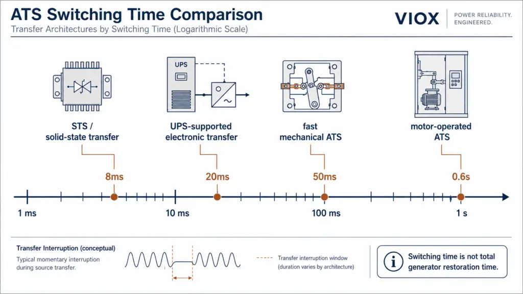
Wenn Ingenieure 8ms, 20ms, 50ms oder 0,6s Umschaltgeschwindigkeitsangaben vergleichen, vergleichen sie nicht immer den gleichen Gerätetyp. Eine 8ms-Umschaltung deutet in der Regel auf eine Halbleiter- oder USV-gestützte Umschaltung hin. Eine 0,6s-Umschaltung deutet meist auf einen motorbetriebenen oder mechanisch betätigten Umschalter hin. Beide können in der jeweiligen Anwendung korrekt sein.
Die eigentliche Frage lautet nicht “Welcher ATS ist am schnellsten?”, sondern vielmehr:
Wie lange kann die angeschlossene Last eine Spannungsunterbrechung tolerieren und welche Umschaltarchitektur ist erforderlich, um innerhalb dieses Grenzwerts zu bleiben?
Wenn Sie zunächst die grundlegende Bedeutung des Geräts benötigen, beginnen Sie mit ATS – Vollständige Bezeichnung in der Elektrotechnik. Wenn Sie die automatische und manuelle Quellenumschaltung vergleichen, lesen Sie Manueller vs. automatischer Umschalter.
Wichtigste Erkenntnisse
- Die Umschaltzeit entspricht nicht der gesamten Überbrückungszeit. Der Wert von 8 ms bis 0,6 s beschreibt in der Regel das Quellenumschaltintervall, nicht die gesamte Zeit, die ein Generator zum Starten und Stabilisieren benötigt.
- Die Sub-Cycle-Umschaltung gehört zu STS- oder elektronischen Umschaltarchitekturen. Herkömmliche mechanische ATS-Mechanismen sind normalerweise nicht für eine echte 8-ms-Umschaltung ausgelegt.
- 20 ms sind ein üblicher Referenzpunkt für die Überbrückungszeit vieler IT-Netzteile,, dies ist jedoch keine allgemeingültige Garantie. Die tatsächliche Toleranz hängt von der Gerätekonstruktion, der Last, der Eingangsspannung und dem Zustand des Netzteils ab.
- 50 ms sind für ein mechanisches Umschaltgerät schnell,, stellen jedoch immer noch eine Unterbrechung dar und können SPS, Schütze, Antriebe oder IT-Geräte ohne Überbrückungsunterstützung zurücksetzen.
- 0,6 s sind in vielen Anwendungen für Generatoren, Beleuchtung, HLK, Pumpen und allgemeine Stromverteilungen akzeptabel,, sind jedoch nicht für Lasten geeignet, die eine unterbrechungsfreie oder nahezu unterbrechungsfreie Stromversorgung erfordern, sofern keine USV, STS oder Energiespeicher verwendet werden.
- Schneller ist nicht automatisch besser. Motoren, Transformatoren und Antriebe erfordern möglicherweise eine verzögerte Umschaltung, eine phasengleiche Umschaltung oder ein Restspannungsmanagement.
- Normen und Projektklassifizierungen sind entscheidend. IEC 60947-6-1, UL 1008, NFPA 110, NEC Artikel 700/701, lokale Vorschriften sowie die zuständige Behörde können die endgültige Spezifikation beeinflussen.
Vergleich der vier Umschaltgeschwindigkeiten von ATS
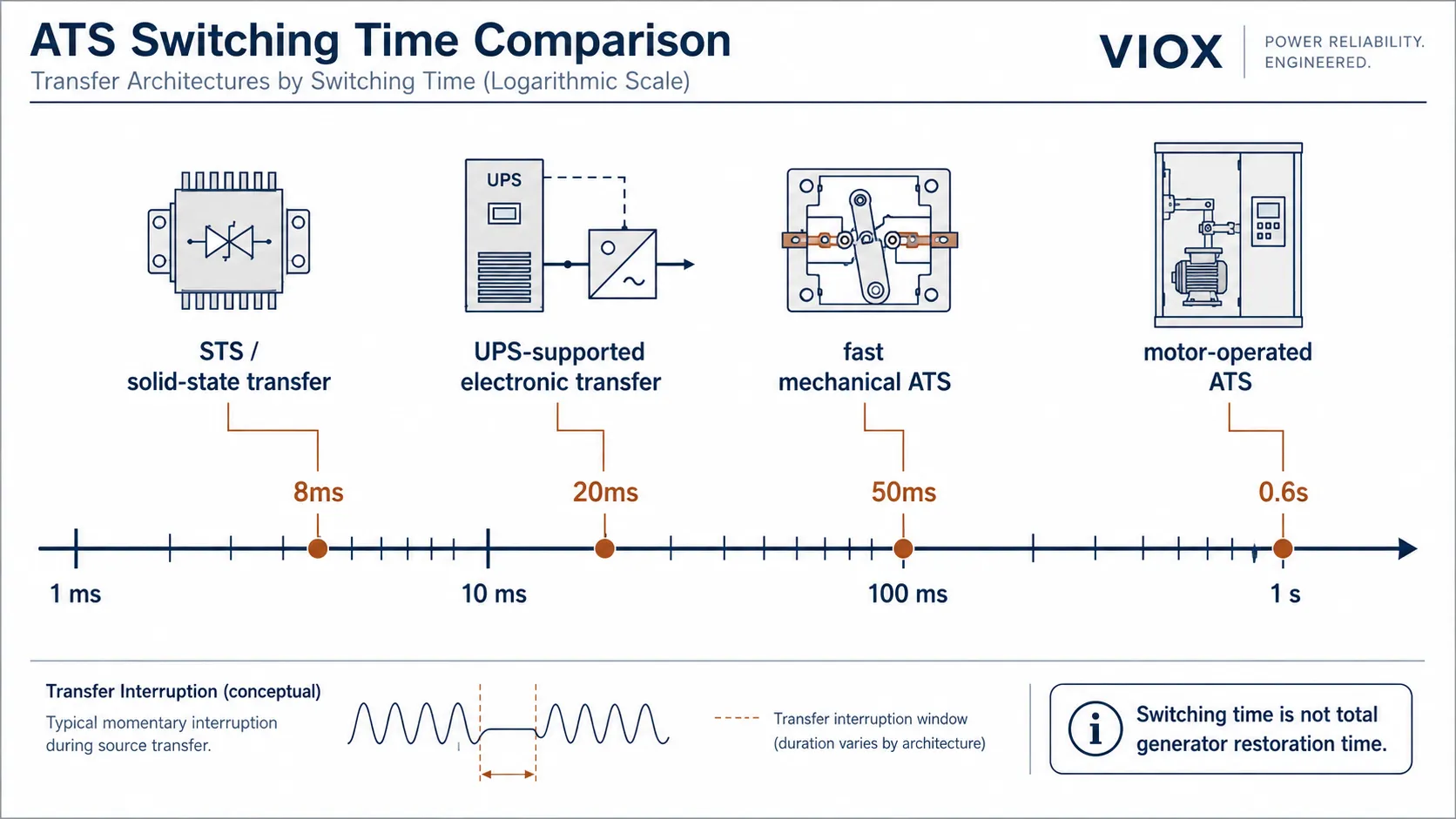
Jede angegebene Geschwindigkeit entspricht einer unterschiedlichen Schaltarchitektur. Der Mechanismus, die Verfügbarkeit der Quelle und die Durchfahrfähigkeit der Last sind ebenso wichtig wie die auf dem Datenblatt angegebene Zahl.
| Schaltgeschwindigkeit | Ca. Zyklen bei 50 Hz / 60 Hz | Typische Schaltarchitektur | Optimale Lasten | Wichtiger Warnhinweis |
|---|---|---|---|---|
| ≤8ms | ≤0,4 / ≤0,48 Perioden | Statischer Transferschalter, USV-Bypass, elektronische Umschaltung | Server, Speicher, Telekommunikation, unterperiodisch kritische IT | Normalerweise kein konventioneller mechanischer ATS |
| ~20ms | ~1 / ~1,2 Zyklen | STS, USV-gestützte Umschaltung, Premium-Schnellumschaltarchitektur | IT-Geräte mit verifizierter Überbrückungszeit, Telekommunikations-Gleichrichter, Steuerungen mit Pufferung | Gehen Sie nicht davon aus, dass alle elektronischen Geräte 20ms überstehen |
| ~50ms | ~2,5 / ~3 Zyklen | Schnelle mechanische ATS, schützbasierte Umschaltung, Umschaltung der PC-Klasse | Allgemeine Elektronik, Beleuchtung, viele industrielle Hilfslasten | Immer noch keine unterbrechungsfreie Umschaltung |
| ~0,6 s | ~30 / ~36 Zyklen | Motorbetriebener ATS, standardmäßiger Netzumschalter, Leistungsschalter-Klasse (CB-Klasse) oder mechanische Umschaltung | Beleuchtung, HLK, Pumpen, Ventilatoren, nicht kritische, generatorgestützte Verteilung | Zu langsam für IT-Lasten, sofern nicht durch USV abgesichert |
Bei 50 Hz entspricht ein Wechselstromzyklus 20 ms. Bei 60 Hz beträgt ein Zyklus etwa 16,7 ms. Deshalb werden bei Diskussionen über Umschaltgeschwindigkeiten häufig sowohl Millisekunden als auch Netzzyklen verwendet.
Umschaltzeit ist nicht gleich Gesamtumschaltzeit
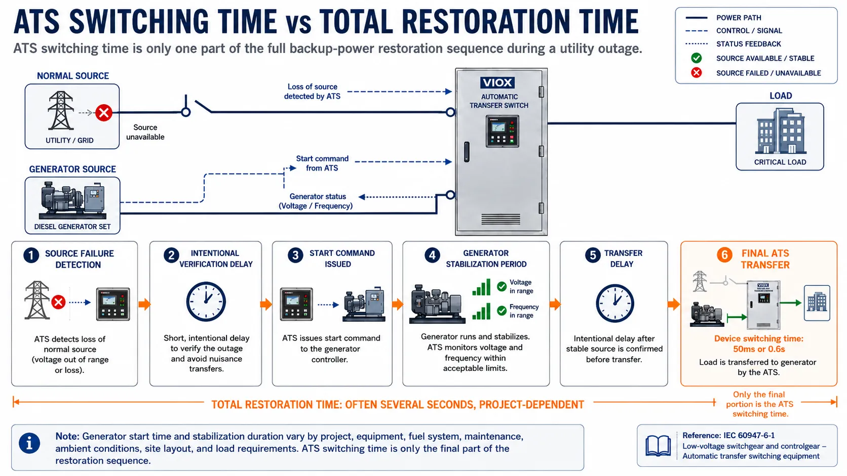
Dies ist der häufigste Spezifikationsfehler bei ATS-Projekten.
Die Millisekundenangabe auf einem Gerätedatenblatt beschreibt in der Regel das Umschalt- oder Übergangsintervall. Eine vollständige Umschaltung von Netz auf Generator kann Folgendes umfassen:
- Erkennung eines Ausfalls der Netzquelle.
- Gezielte Bestätigungsverzögerung zur Vermeidung von Fehlschaltungen.
- Startbefehl für den Generator.
- Anlassen und Starten des Motors.
- Stabilisierung von Generatorspannung und -frequenz.
- Programmierte Umschaltverzögerung.
- Mechanische oder elektronische Umschaltung auf die Ersatzstromquelle.
Das bedeutet, dass ein System mit einem schnellen 50-ms-Schaltmechanismus die Last bei einem tatsächlichen Netzausfall dennoch für mehrere Sekunden ohne Generatorstrom lassen kann. Der ATS hat nicht “mehrere Sekunden zum Umschalten benötigt”; die Ersatzstromquelle war noch nicht bereit.
In der nordamerikanischen Notstrompraxis konzentrieren sich die Systemklassifizierungen nach NFPA 110 sowie die NEC-Anforderungen für Notstrom-/Standby-Systeme häufig auf die Gesamtwiederherstellungszeit und nicht nur auf die Kontaktbewegungszeit. Beispielsweise sind Notstromversorgungssysteme vom Typ 10 mit einer Wiederherstellungserwartung von 10 Sekunden verbunden, während gesetzlich vorgeschriebene Standby-Systeme je nach Code-Ausgabe und Anwendung unterschiedliche Zeitfenster aufweisen können. Überprüfen Sie die genauen Anforderungen immer anhand des aktuellen Regelwerks, der Projektspezifikation und der zuständigen Behörde.
Die Millisekunden-Bemessung wird dann am entscheidendsten, wenn beide Quellen bereits verfügbar sind, wie zum Beispiel bei:
- Umschaltung zwischen zwei Netzversorgungen
- USV-Bypass-Umschaltung
- STS-Quellenauswahl
- doppelt gespeiste Strompfade in Rechenzentren
- Umschaltung nachgelagert zu einer bereits laufenden Ersatzstromquelle
In diesen Fällen kann die Umschaltlücke nahezu der tatsächlichen Unterbrechung entsprechen, die der Verbraucher erfährt.
8ms Umschaltung: Üblicherweise STS- oder USV-Ebene-Umschaltung
Eine Umschaltzeit von 8 ms ist extrem schnell. Dies entspricht etwa einem halben Zyklus bei 60 Hz und weniger als einem halben Zyklus bei 50 Hz.
Diese Geschwindigkeit wird üblicherweise mit Folgendem in Verbindung gebracht:
- statische Umschalteinrichtungen (STS) unter Verwendung von SCRs oder Thyristoren
- USV-Bypass-Systeme
- IT-Stromversorgungssysteme mit zwei Einspeisungen
- Stromversorgungsarchitekturen in der Telekommunikation
- elektronische Umschaltsysteme, bei denen beide Quellen bereits innerhalb der zulässigen Parameter liegen
Herkömmliche mechanische ATS-Mechanismen sind normalerweise nicht für eine Umschaltung innerhalb eines Zyklus ausgelegt. Sie enthalten bewegliche Kontakte, Gestänge, Verriegelungen, Motoren oder Schützmechanismen, und diese Bauteile benötigen eine physische Bewegungszeit.
Wann 8 ms sinnvoll sind
Eine Transferarchitektur der 8-ms-Klasse ist sinnvoll, wenn die Last selbst eine kurze mechanische Unterbrechung nicht tolerieren kann:
- Rechenzentrumsserver
- Speichersysteme
- Telekommunikationsausrüstung
- Netzwerk-Switches
- Steuerungssysteme mit sehr geringer Überbrückungstoleranz
- Medizinische oder Laborelektronik, die eine unterbrechungsfreie Stromversorgung erfordert
- Prozessanlagen, bei denen ein Reset zu erheblichen Ausfallzeiten führt
Ein 8-ms-Umschaltgerät benötigt jedoch zum Zeitpunkt der Umschaltung zwei verfügbare, akzeptable Quellen. Wenn die Ersatzquelle ein Notstromaggregat ist, das noch nicht gestartet wurde, kann das System die Last nicht innerhalb von 8 ms ohne USV, Batteriespeicher, DC-Backup oder eine andere Überbrückungsebene wiederherstellen.
Zur Abgrenzung zwischen ATS und STS siehe Automatische Umschalteinrichtung ATS vs. Statische Umschalteinrichtung STS.
20-ms-Umschaltung: Der Bereich eines Netzzyklus
Bei 50 Hz, entsprechen 20 ms einem vollständigen AC-Zyklus. Bei 60 Hz ist dies etwas länger als ein Zyklus.
Dieser Referenzwert ist wichtig, da viele Netzteile in der Informationstechnik nur über eine kurze Überbrückungsfähigkeit verfügen. Die ITIC/CBEMA-Kurve wird häufig herangezogen, wenn es um die Toleranz von IT-Geräten gegenüber kurzen Spannungsunterbrechungen geht. Sie sollte jedoch nicht als universelle Garantie dafür angesehen werden, dass jeder Computer, jede SPS, jeder Server oder jedes Steuergerät jedes 20-ms-Umschaltereignis übersteht.
Die tatsächliche Überbrückungsfähigkeit hängt ab von:
- Eingangsspannung vor der Unterbrechung
- Lastanteil
- Auslegung der Stromversorgung
- Zustand des Zwischenkreises oder Kondensators
- Alter der Anlage
- ob mehrere Geräte gleichzeitig neu starten
- ob das Gerät über eine Unterspannungsauslöselogik verfügt
Wo 20 ms ausreichen können
Ein Umschaltbereich von 20 ms kann akzeptabel sein für:
- IT-Geräte mit verifizierter Überbrückungszeit der Stromversorgung
- Eingangssysteme von Telekommunikations-Gleichrichtern
- Steuerungselektronik mit Durchfahrvermögen
- USV-gestützte Lasten
- elektronische Geräte mit geringer Leistung, bei denen eine kurzzeitige Unterbrechung akzeptabel ist
Das Risiko
Die riskante Annahme lautet: “20 ms sind schnell genug für Elektronik.”
Manchmal ist das der Fall, manchmal nicht. Die Stromversorgung einer SPS, eine Schützspule, ein Frequenzumrichter-Steuerkreis, ein Sicherheitsrelais oder ein eingebetteter Controller können sich anders verhalten als ein Server-Netzteil. Bei kritischen Systemen sollte die Antwort aus den Gerätespezifikationen, Inbetriebnahmeprüfungen oder der Abnahmeprüfung vor Ort hervorgehen.
50-ms-Umschaltung: Schneller mechanischer ATS, aber dennoch eine Unterbrechung
Eine 50-ms-Umschaltung ist für ein mechanisches Schaltgerät schnell. Dies entspricht etwa 2,5 Perioden bei 50 Hz oder 3 Perioden bei 60 Hz.
Dieser Bereich kann geeignet sein für:
- Beleuchtungskreise
- allgemeine gewerbliche Stromverteilung
- viele Motorlasten
- HVAC-Schalttafeln
- Pumpensteuerungen
- industrielle Hilfslasten
- generatorgestützte Nicht-IT-Verteiler
- Schaltschränke mit verifizierter unterbrechungsfreier Stromversorgung
Allerdings, 50 ms sind keine Null-Unterbrechung. Einige Lasten überbrücken dies. Andere könnten zurückgesetzt werden, ausfallen, auslösen oder einen Alarm auslösen.
Lasten, die empfindlich auf 50 ms reagieren können
Vorsicht bei:
- SPS ohne unterbrechungsfreie Stromversorgung
- Schützspulen für sicherheitskritische Stromkreise
- Frequenzumrichter mit Unterspannungsauslöseeinstellungen
- Prozesssteuerungen
- Sicherheitsrelais
- Sicherheitssysteme
- IT-Geräte ohne USV
- Medizinelektronik
Wenn ein Lastverlust inakzeptabel ist, verwenden Sie eine USV-Unterstützung, eine STS-Architektur, eine unterbrechungsfreie Umschaltung (Closed-Transition) oder eine lokale Überbrückung der Steuerspannung.
0,6 s Umschaltzeit: Normal für viele mechanische ATS-Anwendungen
Ein 0,6 s Umschaltzeit ist deutlich langsamer als 8 ms, 20 ms oder 50 ms, bedeutet jedoch nicht automatisch eine schlechte Leistung. Es gehört zu einer anderen Anwendungskategorie.
Für viele motorbetriebene automatische Umschalteinrichtungen und Netzumschalter ist eine Umschaltzeit im Bereich von Hunderten von Millisekunden akzeptabel, da die angeschlossenen Lasten eine kurze Stromunterbrechung tolerieren können.
Zu den üblichen Anwendungen gehören:
- Notstromgeneratorsysteme
- nicht kritische Verteiler
- Pumpen und Ventilatoren
- Beleuchtungskreise
- HVAC-Systeme
- landwirtschaftliche Geräte
- kleine Industrieschaltschränke
- Notstromkreise für Wohn- oder Gewerbegebäude
Bei diesen Systemen ist der größere Ausfallfaktor oft nicht der 0,6-Sekunden-Schaltvorgang, sondern die Start- und Stabilisierungssequenz des Generators.
Wie der Schaltmechanismus die Geschwindigkeit bestimmt
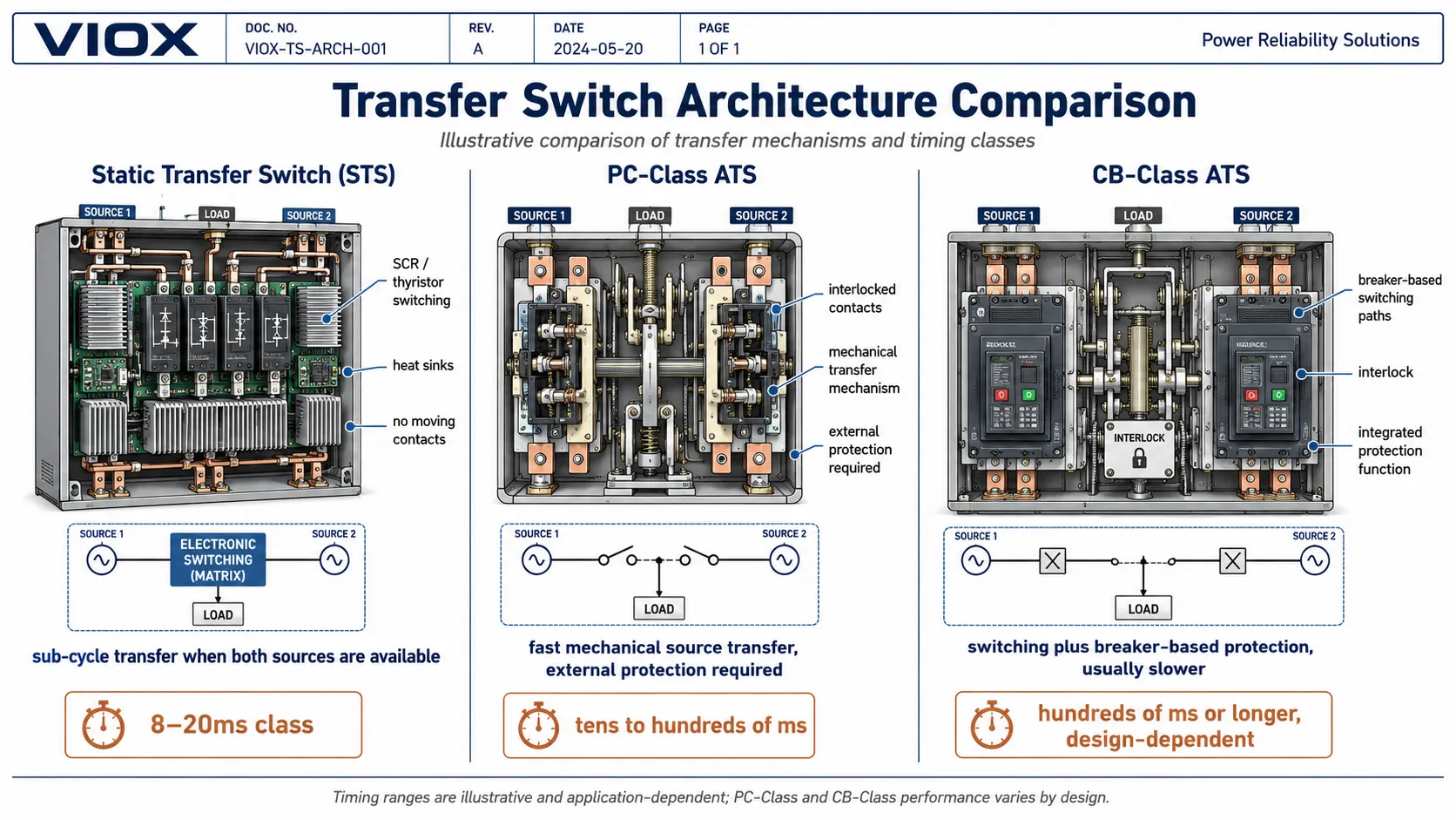
Geschwindigkeit, Schutz und Lebensdauer werden durch das Schaltelement bestimmt. In der IEC-Terminologie für Umschalteinrichtungen können Umschaltgeräte in Bezug auf Folgendes diskutiert werden: PC-Klasse und CB-Klasse Geräte gemäß IEC 60947-6-1. Bei nordamerikanischen Anwendungen werden Umschalteinrichtungen üblicherweise bewertet nach UL 1008.
| Attribut | Statischer Transferschalter (STS) | PC-Klasse ATS | CB-Klasse ATS |
|---|---|---|---|
| Schaltelement | SCR- / Thyristor- / Halbleiterpfad | Kontakte, Schütze oder Schaltmechanismus ohne integrierten Auslöseschutz | Schaltpfad auf Basis von Leistungsschaltern |
| Typischer Umschaltbereich | Sub-Zyklus bis zu einem Zyklus bei verfügbaren Quellen | Zehn bis hunderte Millisekunden, abhängig von der Ausführung | Oft hunderte Millisekunden oder länger |
| Bewegliche Leistungskontakte | Keine | Ja | Ja |
| Integrierter Überstromschutz | Nein; externer Schutz erforderlich | Nein; externer Schutz erforderlich | Ja, abhängig von der Ausführung |
| Am besten geeignet für | Kritische IT- und Telekommunikationsumschaltung zwischen spannungsführenden Quellen | Hochleistungsfähige Quellenumschaltung | Einspeisungen, die eine Schaltfunktion sowie einen leistungsschalterbasierten Schutz erfordern |
| Wesentlicher Zielkonflikt | Schnellste Umschaltung, höhere Systemintegration | Schnelle mechanische Quellenumschaltung | Schutzintegration, oft langsamerer Mechanismus |
Die praktische Konsequenz: Geschwindigkeit und Schutz sind unterschiedliche Auslegungsachsen. Ein schneller ATS der PC-Klasse benötigt möglicherweise dennoch einen vor- oder nachgeschalteten Schutz. Ein ATS der CB-Klasse kann zwar einen Schutz integrieren, schaltet jedoch langsamer um. Ein STS kann sehr schnell umschalten, gehört jedoch nicht zur gleichen Produktkategorie wie ein Generator-ATS.
Für einen tieferen Auswahlkontext siehe Auswahlhilfe für ATS der PC-Klasse vs. CB-Klasse und Open vs. Closed Transition ATS-Auswahlhilfe.
Unterbrechende Umschaltung, verzögerte Umschaltung, unterbrechungsfreie Umschaltung und statische Umschaltung
Die Umschaltgeschwindigkeit hängt auch von der Umschaltmethode ab.
| Umschaltart | Wie es funktioniert | Unterbrechungsprofil | Typische Verwendung |
|---|---|---|---|
| Unterbrechende Umschaltung (ATS) | Trennung von einer Quelle vor der Verbindung mit der anderen | Definierte Unterbrechung | Die meisten Generator-Umschaltanlagen |
| Umschaltanlage mit verzögerter Umschaltung (Delayed Transition ATS) | Fügt eine beabsichtigte Neutral-/Aus-Zeit zwischen den Quellen hinzu | Längere kontrollierte Unterbrechung | Motoren, Transformatoren, Abklingen der Restspannung |
| Umschaltanlage mit unterbrechungsfreier Umschaltung (Closed Transition ATS) | Parallelschaltung zweier akzeptabler synchronisierter Quellen für einen kurzen Moment | Geringe oder keine Unterbrechung während der geplanten Umschaltung | Prüfung, Rückschaltung, kritische Infrastrukturen |
| Statischer Transferschalter (STS) | Nutzt Halbleiterschaltung zwischen zwei verfügbaren Quellen | Sehr schnelle Umschaltung, oft innerhalb eines Teilzyklus | Rechenzentren, Telekommunikation, kritische Elektronik |
Eine unterbrechungsfreie Umschaltung (Closed Transition) kann die Unterbrechung bei geplanten Umschaltungen oder Rückschaltungen reduzieren, sofern beide Quellen vorhanden, zulässig und synchronisiert sind. Dies ist keine magische Lösung für eine unterbrechungsfreie Versorgung bei einem vollständigen Ausfall der Quelle. Wenn die normale Quelle ausfällt und die alternative Quelle nicht bereits verfügbar ist, muss eine andere Überbrückungsquelle die Last stützen.
Auswahl der richtigen Umschaltgeschwindigkeit für Ihre Anwendung
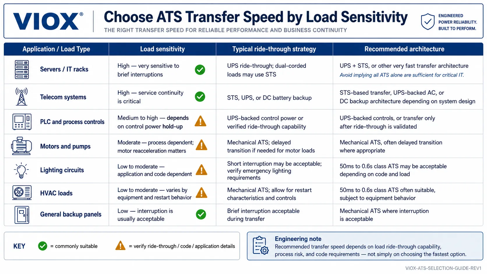
Passen Sie die Umschaltgeschwindigkeit an die Lastempfindlichkeit an, nicht an den kleinsten Wert im Katalog.
| Anwendung | Strategie zur Umschaltgeschwindigkeit | Typische Architektur |
|---|---|---|
| IT-Sammelschiene im Rechenzentrum | Umschaltung innerhalb eines Teilzyklus oder eines Zyklus | STS nachgeschaltet bei dualen USV- oder Netzpfaden |
| Telekommunikations-Vermittlungsstelle | Sehr schnelle Umschaltung plus DC-Überbrückung | STS, USV, Gleichstromanlage oder redundantes Gleichrichterdesign |
| SPS und Prozesssteuerung | Die Überbrückungszeit für die Steuerspannung ist oft wichtiger als die Umschaltgeschwindigkeit des ATS | USV-gestützte Steuerstromversorgung oder verifizierte DC-Überbrückung |
| Sicherheitsrelevante Lasten in Krankenhäusern | Einhaltung der normativ festgelegten Wiederherstellungsanforderungen | Generator und ATS gemäß Projektstandard ausgelegt |
| Motoren und Pumpen | Mechanische ATS können akzeptabel sein; eine verzögerte Umschaltung kann vorteilhaft sein | ATS der PC-Klasse oder CB-Klasse mit Koordination für den Motorwiederanlauf |
| Kommerzielle Notstromversorgung | Hunderte von Millisekunden bis zu mehreren Sekunden können akzeptabel sein | Motorbetriebene ATS oder Umschalteinrichtung für zwei Stromquellen |
| Wohngebäude- oder Solar-Hybrid-Backup | Abhängig von Wechselrichter, Batterie, Generator und Lasttoleranz | Schnelle ATS, Wechselrichterumschaltung oder USV für empfindliche Lasten |
Für geschäftskritische IT-Infrastrukturen ist die Architektur wichtiger als die reine Anzahl der ATS-Einheiten. Eine USV überbrückt die Zeit bis zum Anlaufen des Generators, während ein STS oder ein elektronisches Transfersystem die Quellenauswahl zwischen aktiven Quellen übernimmt. Bei generatorgestützten Standby-Systemen ist die Umschaltzeit im Sub-Sekunden-Bereich oft weniger entscheidend als die Erkennung der Quelle, die Zuverlässigkeit des Generatorstarts und die korrekte Lastklassifizierung.
Checkliste für die praktische Spezifikation
Bevor Sie die Umschaltzeit eines ATS spezifizieren, klären Sie folgende Punkte:
- Um welche Lastart handelt es sich: IT, Motor, Beleuchtung, Steuerung, Medizintechnik, Prozessleittechnik, HLK oder allgemeine Stromverteilung?
- Ist die Ersatzstromquelle bereits verfügbar oder muss sie erst gestartet werden?
- Bezieht sich der Wert im Datenblatt auf die Übergangszeit, die mechanische Umschaltzeit, die Lastunterbrechungszeit oder die Gesamtwiederherstellungszeit?
- Handelt es sich um eine offene, verzögerte, geschlossene oder statische Umschaltung?
- Kann die Last die angegebene Unterbrechung tolerieren?
- Ist eine USV, eine DC-Pufferung oder eine Überbrückung der Steuerspannung erforderlich?
- Sind für eine unterbrechungsfreie Umschaltung (Closed Transition) eine Netzsynchronisation und die Genehmigung des Energieversorgers erforderlich?
- Handelt es sich bei dem Gerät um die PC-Klasse, CB-Klasse, ein STS, eine Wechselrichterumschaltung oder eine andere Architektur?
- Erfordert das Projekt die Einhaltung von IEC 60947-6-1, UL 1008, NFPA 110, NEC Artikel 700/701 oder einer anderen lokalen Norm?
- Wird das Umschaltverhalten während der Inbetriebnahme überprüft?
Für die Logik der Vor-Ort-Prüfung und Inbetriebnahme siehe Wie man einen automatischen Umschalter (ATS) sicher testet.
Häufige Auswahlfehler
Fehler 1: Vergleich eines 8ms-STS mit einem 0,6s-ATS, als wären es dieselben Geräte
Ein STS und ein mechanischer ATS lösen unterschiedliche Probleme. Ein STS schaltet sehr schnell zwischen akzeptablen stromführenden Quellen um. Ein mechanischer ATS wird häufig verwendet, um die Umschaltung auf eine generatorgestützte Stromversorgung sicher und wirtschaftlich zu verwalten.
Fehler 2: Verwechslung von Umschaltzeit mit der gesamten Ausfallzeit
Ein 50-ms-ATS bedeutet nicht, dass die Last 50 ms nach einem Netzausfall wiederhergestellt ist, wenn die alternative Quelle ein Generator ist. Der Start und die Stabilisierung des Generators bestimmen die Dauer des Ausfalls.
Fehler 3: Die Annahme, dass eine schnellere Umschaltung immer besser ist
Einige Lasten profitieren von einer verzögerten Umschaltung. Motoren, Transformatoren und Antriebe benötigen möglicherweise Zeit, bis die Restspannung vor dem Wiedereinschalten abgeklungen ist. Eine schnelle Umschaltung kann nützlich sein, ist aber nicht universell korrekt.
Fehler 4: Ignorieren der Quellensynchronisation
Eine unterbrechungsfreie Umschaltung (Closed Transition) erfordert akzeptable Spannungs-, Frequenz- und Phasenbeziehungen zwischen den Quellen. Ohne Synchronisation und Freigabe kann das Parallelschalten von Quellen ein erhebliches Systemrisiko darstellen.
Fehler 5: Auswahl der ATS-Geschwindigkeit ohne Lastprüfung
Wenn die Last kritisch ist, verlassen Sie sich nicht nur auf Katalogwerte. Bestätigen Sie die Überbrückungstoleranz, testen Sie das Umschaltverhalten bei der Inbetriebnahme und dokumentieren Sie die akzeptablen Ergebnisse.
FAQ
Was ist die Umschaltzeit eines ATS?
Die ATS-Umschaltzeit ist die Zeit, die das Umschaltgerät benötigt, um die Lastverbindung nach dem Umschaltbefehl von einer Quelle auf eine andere zu übertragen. Sie umfasst möglicherweise nicht die Quellenerkennung, programmierte Verzögerungen, den Generatorstart, die Quellenstabilisierung oder die Rückschaltlogik.
Ist eine ATS-Umschaltzeit von 8 ms realistisch?
8 ms sind für statische Umschalter (STS), USV-Bypass-Systeme und elektronische Umschaltarchitekturen realistisch. Für ein herkömmliches mechanisches ATS mit beweglichen Leistungskontakten ist dies in der Regel nicht realistisch.
Kann ein mechanisches ATS in 8 ms umschalten?
Herkömmliche mechanische ATS-Geräte sind normalerweise nicht für eine Umschaltung innerhalb eines Netzzyklus ausgelegt. Wenn ein Datenblatt 8 ms angibt, prüfen Sie, ob es sich bei dem Gerät tatsächlich um ein STS, ein hybrides elektronisches Umschaltsystem, einen USV-Bypass oder eine andere Architektur handelt.
Sind 20 ms schnell genug für Computer?
Manchmal, aber nicht immer. Viele IT-Netzteile können kurze Unterbrechungen überbrücken, aber die Toleranz hängt vom Design des Netzteils, der Last, der Eingangsspannung, dem Zustand der Kondensatoren und dem Vorhandensein einer USV-Unterstützung ab.
Gilt eine Umschaltzeit von 50 ms bei einem ATS als schnell?
Ja, 50 ms sind für eine mechanische Umschalteinrichtung schnell. Es handelt sich dennoch um eine Unterbrechung, sodass SPS, Antriebe, Schützspulen und empfindliche Elektronik möglicherweise zurückgesetzt werden, sofern sie nicht über eine Überbrückungsfunktion verfügen.
Ist 0,6 s zu langsam für ein ATS?
Nicht für viele Anwendungen in den Bereichen Generatoren, Beleuchtung, HLK, Pumpen und allgemeine Stromverteilung. Für Lasten, die eine unterbrechungsfreie Stromversorgung erfordern, ist dies zu langsam, es sei denn, diese Lasten werden durch eine USV, ein STS, eine Wechselrichterumschaltung oder ein anderes Überbrückungssystem gestützt.
Verringert ein schnelleres ATS die Startverzögerung des Generators?
Nein. Wenn die alternative Quelle ein Generator ist, muss der Generator starten und sich stabilisieren, bevor die Umschaltung erfolgt. Die Schaltgeschwindigkeit des ATS beschreibt nur einen Teil des gesamten Ausfallsequenz-Vorgangs.
Was ist der Unterschied zwischen der Umschaltzeit eines ATS und eines STS?
Ein ATS verwendet üblicherweise mechanische Schaltvorgänge und wird häufig für die Umschaltung von Generatoren oder in der Energieverteilung eingesetzt. Ein STS verwendet Halbleiterschalter und ist für eine sehr schnelle Umschaltung zwischen verfügbaren Quellen konzipiert, typischerweise in Rechenzentren, Telekommunikationssystemen und kritischen Stromversorgungsanwendungen.
Kann ein ATS mit unterbrechungsfreier Umschaltung (Closed-Transition) eine Umschaltung ohne Unterbrechung gewährleisten?
Eine unterbrechungsfreie Umschaltung (Closed-Transition) kann Unterbrechungen bei geplanten Umschaltvorgängen reduzieren oder eliminieren, sofern beide Quellen vorhanden, zulässig und synchronisiert sind. Sie bietet keine unterbrechungsfreie Umschaltung bei einem vollständigen Ausfall der Quelle, es sei denn, eine weitere Energiequelle stützt die Last.
Zugehörige VIOX-Ressourcen
- ATS – Vollständige Bezeichnung in der Elektrotechnik
- Manueller vs. automatischer Umschalter
- Automatische Umschalteinrichtung ATS vs. Statische Umschalteinrichtung STS
- Open vs. Closed Transition ATS-Auswahlhilfe
- Auswahlhilfe für ATS der PC-Klasse vs. CB-Klasse
- Einphasen- vs. Drehstrom-ATS-Auswahlhilfe
- Wie man einen automatischen Umschalter (ATS) sicher testet
Quellen und referenzierte Standards
- IEC 60947-6-1 Normenreihe – Umschalteinrichtungen
- UL 1008 Normenreihe – Umschalteinrichtungen (Transfer Switch Equipment)
- NFPA 110 – Standard für Notstrom- und Bereitschaftsstromversorgungssysteme
- Übersicht über Umschalteinrichtungen: Konzepte der offenen Umschaltung (Open Transition), unterbrechungsfreien Umschaltung (Closed Transition) und statischen Umschaltung (Static Transfer)
