Na této stránce
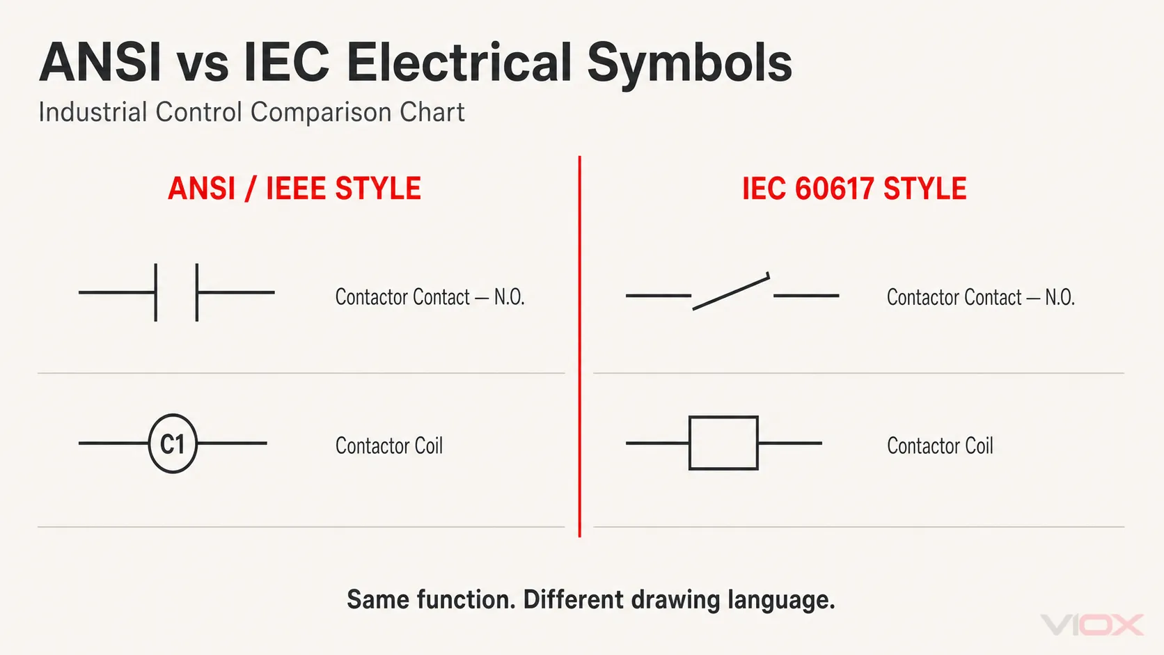
Elektrické značky jsou grafické symboly používané k reprezentaci komponent, zapojení a funkcí ve schématech a řídicích diagramech. Stejná elektrická funkce může vypadat odlišně v závislosti na konvenci výkresu: cívka stykače se může v běžném výkresu stylu ANSI/IEEE jevit jako kruh a ve výkresu stylu IEC jako obdélník.
Tento tabulka elektrických značek porovnává 29 běžně se vyskytujících průmyslových řídicích značek ve dvou sloupcích: styl ANSI/IEEE a styl IEC 60617. Zahrnuje kontakty, časované kontakty, ovládací prvky, procesní spínače, cívky, akční členy, signalizační zařízení, svorky, jističe a pojistky.
Použijte tabulku k identifikaci rodiny značek, poté před zapojením nebo servisem zařízení potvrďte legendu projektu, označení zařízení, čísla svorek a příslušnou dokumentaci.
Co tento přehled elektrických značek obsahuje
| kategorie použití | Zahrnuté značky | Počet |
|---|---|---|
| Základní kontakty | Stykač NO/NC; řídicí relé NO/NC. | 4 |
| Časované kontakty | NO/NC kontakty se zpožděným sepnutím a zpožděným vypnutím | 4 |
| Ovládací prvky | Přepínač; tlačítka NO/NC; hřibové tlačítko | 4 |
| Senzory a procesní spínače | Hladinové, průtokové, tlakové, teplotní, koncové a přibližovací spínače | 6 |
| Cívky a akční členy | Řídicí relé, stykač, motorový spouštěč, časové relé, solenoid a čítač | 6 |
| Signalizace, připojení a ochrana | Indikační světlo, zástrčka/zásuvka, svorky, jistič a pojistka | 5 |
| Celkem | 29 |
Tato tabulka je záměrně zaměřena na výkresy průmyslového řízení a rozváděčů nízkého napětí. Symboly elektronických součástek, jako jsou tranzistory, operační zesilovače a logické členy, patří k jinému záměru vyhledávání a nejsou zde zahrnuty.
Čtěte čtyři věci společně: symbol, označení, svorku a stav
Symbol sám o sobě málokdy poskytuje dostatek informací. Přesná interpretace výkresu závisí na čtyřech samostatných vrstvách.
| Prvek výkresu | Co vám to říká | Příklad |
|---|---|---|
| Grafický symbol | Funkce zařízení nebo činnost kontaktu | Coil, N.O. contact, fuse, circuit breaker |
| Referenční označení | Ke které instanci zařízení symbol patří | Projekt může používat systém označování CR, KM, KA, QF nebo jiný |
| Označení svorek | Místo, kde se vodiče připojují k fyzickému zařízení | A1/A2, 13/14, 21/22 nebo svorky specifické pro výrobce |
| Normální stav a poznámky | Stav, ve kterém je symbol vykreslen | Stav bez napětí, neaktivovaný stav, stav bez tlaku nebo jiný definovaný klidový stav |
Referenční označení nejsou pouze součástí symbolu. Jejich struktura může následovat firemní konvenci, regionální zvyklosti nebo systém založený na řadě IEC 81346. Pokud je zkratka neznámá, použijte legendu projektu a VIOX’s referenční seznam plných názvů v elektrotechnice namísto pouhého hádání z písmen.
Základní symboly kontaktů: normálně otevřený (N.O.) a normálně zavřený (N.C.).
Normálně otevřené (N.O.) a normálně zavřené (N.C.) kontakty jsou obvykle zobrazeny ve svém definovaném klidovém stavu. U běžného relé nebo stykače to obvykle znamená, že cívka je bez napětí a ovládací prvek není aktivován.
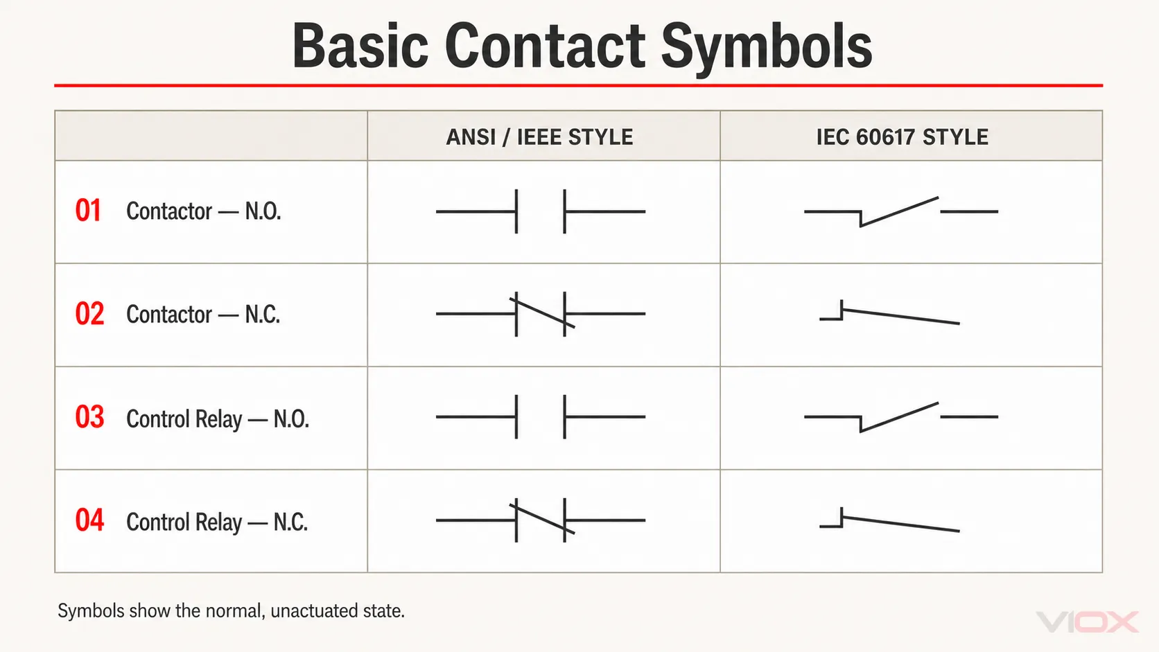
Grafický tvar identifikuje stav kontaktu, ale ne vždy identifikuje kompletní fyzické zařízení. Pomocný kontakt stykače a kontakt řídicího relé mohou používat stejnou základní geometrii kontaktu. Referenční štítek propojuje tento kontakt se správnou cívkou nebo zařízením jinde ve výkresu.
Pro přepínací kontakty s více než jedním pólem viz samostatný průvodce symboly relé SPDT vs DPDT.
Symboly časovaných kontaktů: zpožděný přítah (ON-Delay) vs. zpožděný odpad (OFF-Delay)
Časované kontakty přidávají k normálnímu stavu kontaktu akci závislou na čase:
- Zpožděný přítah (ON-delay): časovaná akce nastane poté, co je aktivován časovací vstup nebo cívka.
- Zpožděný odpad (OFF-delay): časovaná akce nastane poté, co je odstraněn iniciační signál nebo se změní časovací podmínka, v závislosti na konstrukci zařízení.
- NO nebo NC: popisuje normální stav kontaktu, nikoliv směr zpoždění.
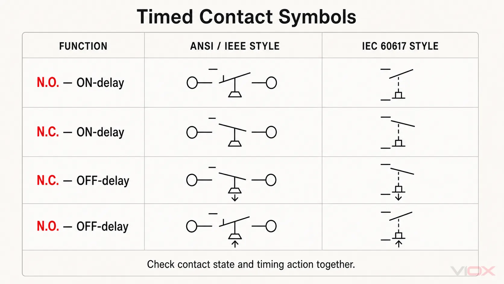
Vždy interpretujte stav kontaktu a časovou značku společně. Tabulka symbolů vám neřekne skutečný rozsah zpoždění, chování při resetu, metodu spouštění ani uspořádání napájení. Tyto podrobnosti pocházejí ze schématu zařízení a technického listu. Průvodce časovými relé společnosti VIOX’s průvodce časovými relé vysvětluje, jak symbol souvisí se zpožděným sepnutím, zpožděným vypnutím a dalšími funkcemi časovače.
Symboly přepínačů a tlačítek
Symboly ovládacích prvků kombinují stav kontaktu s ručním ovladačem. Níže uvedená tabulka porovnává přepínače, normálně otevřená a normálně zavřená tlačítka a obecné hřibové tlačítko.
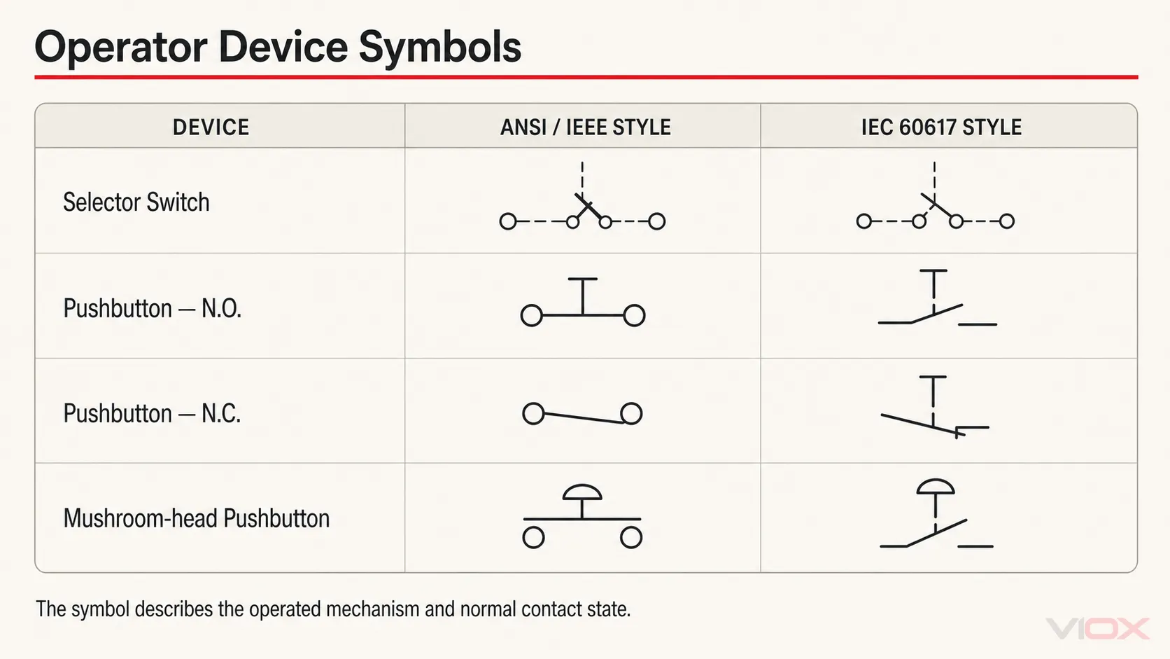
Hřibovitý ovladač automaticky nedokazuje, že se jedná o zařízení pro nouzové zastavení. Funkce nouzového zastavení vyžadují správné zařízení, činnost kontaktu, bezpečnostní architekturu, označení a příslušné požadavky na strojní zařízení. Symbol interpretujte společně s bezpečnostními poznámkami a dokumentací k zařízení, namísto určování funkce pouze podle tvaru ovladače.
Symboly senzorů a procesních spínačů
Procesní a polohové spínače používají symbol kontaktu doplněný kvalifikátorem nebo značkou akčního členu, která udává, co kontakt ovládá. Níže uvedených šest příkladů pokrývá spínání hladiny kapaliny, průtoku, tlaku, teploty, mezní polohy a přiblížení.
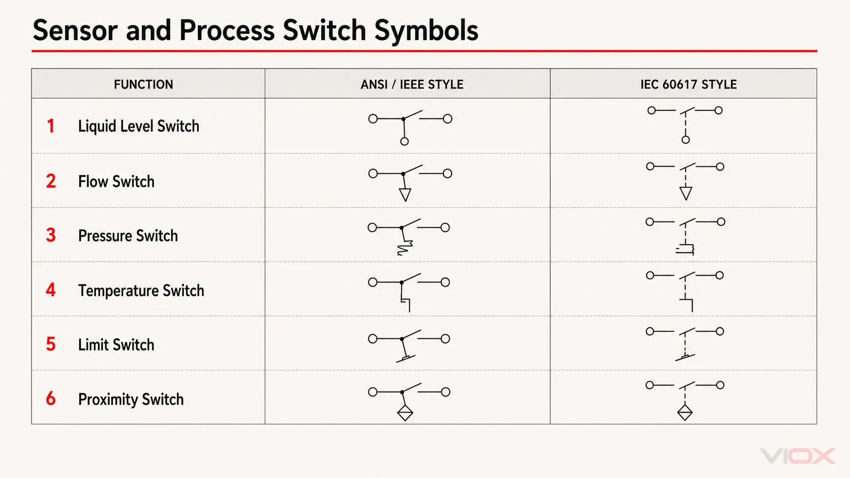
Při čtení těchto symbolů si položte dvě otázky:
- Jaká fyzikální veličina nebo pohyb spínač ovládá?
- V jakém stavu je kontakt za normálních podmínek definovaných výkresem?
Výkres by měl rovněž identifikovat nastavenou hodnotu, umístění zařízení, procesní podmínky nebo křížový odkaz, pokud jsou tyto informace nezbytné. Samotný symbol nedefinuje rozsah kalibrace, technologii snímání, typ výstupu ani odolnost vůči vlivům prostředí.
Symboly cívek a akčních členů
Cívky převádějí elektrický vstup na spínací nebo mechanický pohyb. V běžných severoamerických řídicích výkresech je cívka relé nebo stykače často znázorněna označeným kruhem. Výkresy podle normy IEC běžně používají obdélník s kvalifikátorem v případě, že má zařízení specifickou funkci, jako je časování nebo elektromagnetické ovládání.
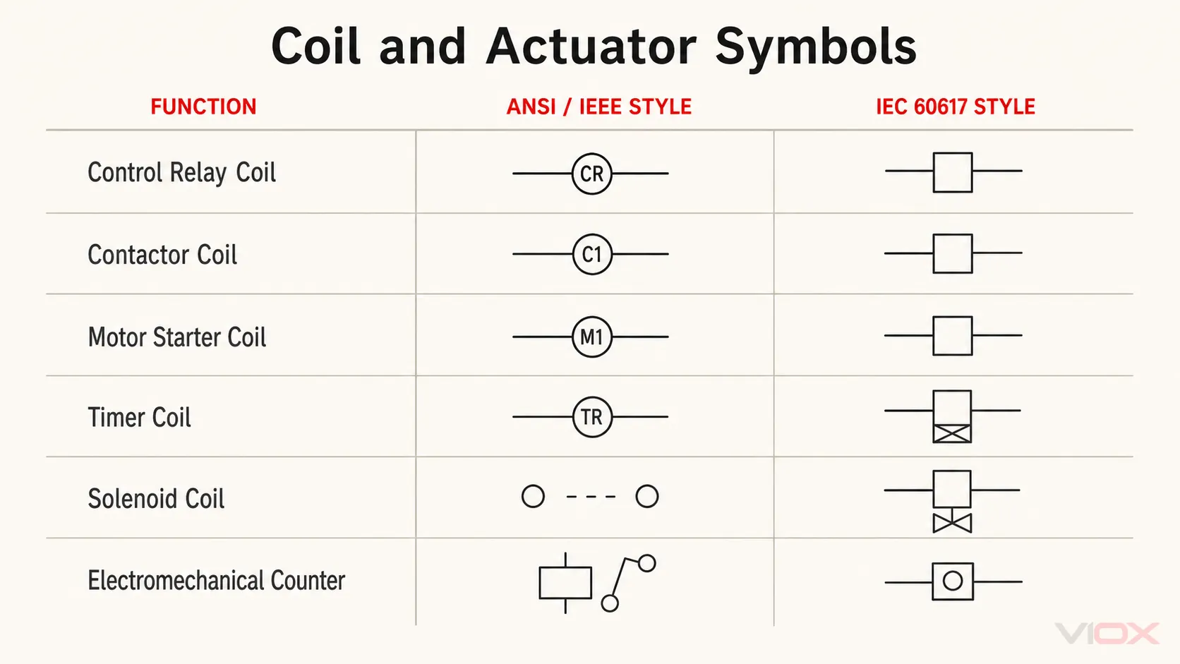
Cívka a její kontakty se mohou nacházet na různých stranách nebo v různých příčkách žebříkového diagramu. Přiřaďte je k sobě pomocí referenčního označení a informací o křížových odkazech. Nepředpokládejte, že dvě podobně tvarované cívky patří ke stejnému zařízení.
Symboly signálů, připojení a ochrany
Poslední skupina zahrnuje zařízení, která indikují stav, spojují vodiče nebo přerušují abnormální proud.
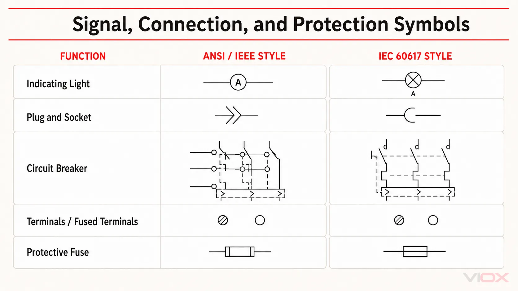
Důležitá rozhraní zahrnují:
- . signalizační kontrolka symbol znázorňuje signalizační funkci; její napětí, barva a technologie světelného zdroje vyžadují samostatnou dokumentaci.
- A zástrčka a zásuvka symbol označuje rozpojitelné spojení, nikoliv fyzickou řadu konektorů nebo zapojení pinů.
- A symbol svorky identifikuje připojovací bod; číslování svorek a to, zda je jištěna, musí být ověřeno z výkresu a kusovníku.
- A jistič symbol identifikuje funkci přerušení a ochrany, ale neuvádí jmenovité hodnoty jističe, vypínací charakteristiku, vypínací schopnost ani certifikaci.
- A symbol pojistky sám o sobě neurčuje rychlostní třídu ani kategorii použití. Pro tyto rozdíly použijte podrobný průvodce elektrickými symboly pojistek.
Styl ANSI/IEEE vs. styl IEC 60617
Oba sloupce by měly být považovány za výkresové jazyky, nikoli za konkurenční úrovně kvality.
| Bod | Výkresy ve stylu ANSI/IEEE | IEC 60617-style drawings |
|---|---|---|
| Typický kontext | Severoamerická dokumentace průmyslového řízení a knihovny starších výkresů | Mezinárodní elektrotechnická schémata a dokumentace strojních zařízení určených pro export |
| Běžný vizuální rozdíl | Cívky jsou často kruhové a mohou obsahovat zkratku zařízení | Cívky jsou obvykle obdélníkové, v případě potřeby se samostatnými kvalifikátory |
| Identifikace zařízení | Často používá známé severoamerické zkratky nebo značky specifické pro daný projekt | Může používat značky orientované na IEC nebo referenční označovací systém podle IEC 81346 |
| Konečná autorita | Projektová legenda, příslušná dokumentace a zavedená firemní/oborová praxe | Projektová legenda a databáze IEC 60617 nebo přijatá projektová norma |
Na stránkách Databáze IEC 60617 je oficiálním zdrojem IEC pro grafické značky používané v elektrotechnických schématech. Obsahuje mnohem více značek a aplikačních metadat, než se vejde do praktické tabulky na blogu.
IEEE/ANSI 315-1975 je stále široce citována ve starších knihovnách a vzdělávacích materiálech, ale IEEE ji v současnosti uvádí jako Neaktivní-vyhrazená. Z tohoto důvodu tento článek používá vymezený termín styl ANSI/IEEE namísto tvrzení, že každá grafika v levém sloupci je aktuálním univerzálním požadavkem ANSI. Vždy si ověřte, co skutečně vyžaduje smlouva, zákazník, úřad nebo firemní norma výkresů.
Jak číst průmyslový elektrický výkres
Použijte tento postup namísto interpretace jednotlivých symbolů po jednom.
1. Přečtěte si rohové razítko a legendu
Potvrďte typ výkresu, revizi, platnou konvenci, napěťovou soustavu a seznam zkratek. Pokud výkres obsahuje legendu specifickou pro projekt, má přednost před předpoklady založenými na obecné tabulce.
2. Identifikujte typ výkresu
- A schéma klade důraz na elektrickou funkci a řídicí logiku.
- A schéma zapojení klade důraz na fyzické připojovací body a trasování vodičů.
- A jednopólové schéma redukuje vícevodičovou elektrickou soustavu na funkční přehled.
- A rozmístění v rozváděči ukazuje fyzické umístění a nenahrazuje schéma zapojení.
3. Stanovte normální stav
Určete, zda výkres definuje zařízení jako bez napětí, bez tlaku, v klidovém stavu nebo v jiném normálním stavu. To je zásadní při interpretaci NO/NC kontaktů, tlakových spínačů, koncových spínačů a časovaných kontaktů.
4. Sledujte silové a řídicí obvody odděleně
Sledujte hlavní silovou cestu přes odpojování, jištění, spínání a zátěž. Poté sledujte řídicí cestu přes tlačítka, blokování, kontakty relé, cívky, senzory a indikátory.
5. Přiřaďte cívky ke kontaktům
Používejte štítky a křížové odkazy k nalezení každého kontaktu ovládaného cívkou relé, stykače, spouštěče nebo časového relé. Fyzická blízkost na stránce nedokazuje, že symboly patří ke stejnému zařízení.
6. Před zapojením ověřte svorky
Schéma vysvětluje funkci; schéma svorek od výrobce potvrzuje skutečné body připojení. Před prováděním změn zkontrolujte označení zařízení, technický list, čísla vodičů, plán svorek a kusovník.
Pro kontroly ve fázi uvádění do provozu použijte příručku VIOX pro chybách elektrických panelů před zapnutím.
Časté chyby při čtení elektrických symbolů
- Považovat schéma za návod k zapojení: porovnání symbolů neposkytuje přiřazení svorek ani jmenovité hodnoty produktu.
- Předpokládat, že označení jsou univerzální: označení KM, KA, CR, QF a podobná závisí na zvoleném referenčním systému a projektové praxi.
- Čtení kontaktů v provozním stavu: většina symbolů kontaktů je vykreslena v definovaném normálním stavu.
- Nazývat každé zařízení s hřibovitým ovladačem nouzovým zastavením: samotný tvar akčního členu nestanovuje bezpečnostní funkci.
- Záměna schématu zapojení s rozložením v rozváděči: funkční vztahy neukazují přesnou montážní polohu ani trasu kabelů.
- Ignorování legendy při kombinaci stylů: importovaná zařízení a upravené výkresy mohou obsahovat více než jednu konvenci.
ČASTO KLADENÉ DOTAZY
Co je tabulka elektrických značek?
Tabulka elektrických značek seskupuje grafické symboly používané k reprezentaci zařízení a funkcí ve schématech. Užitečná tabulka také identifikuje výkresovou konvenci a vysvětluje, jak značky souvisejí s označením, svorkami a normálními stavy.
Jsou elektrické značky ANSI a IEC stejné?
Ne vždy. Některé funkce vypadají podobně, zatímco jiné – zejména cívky, kontakty, časovaná zařízení a ovládací mechanismy – mohou být kresleny odlišně. Projektová legenda a příslušná dokumentace zůstávají konečnou autoritou.
Co je IEC 60617?
IEC 60617 je databáze grafických značek IEC pro elektrotechnická schémata. Zahrnuje vodiče, součástky, spínací přístroje, řídicí přístroje, ochranné přístroje, měřicí přístroje, signalizační zařízení a další kategorie.
Jaký je rozdíl mezi IEC 60617 a IEC 81346?
IEC 60617 addresses graphical symbols used in diagrams. The IEC 81346 series addresses system structuring, object classification, and reference designations. A drawing may therefore use an IEC 60617-style symbol and a separate IEC 81346-based device identifier.
Proč mohou kontakt stykače a kontakt relé vypadat stejně?
Značka kontaktu popisuje spínací stav a funkci. Příslušná cívka, referenční označení, kontext obvodu a dokumentace určují, zda kontakt patří ke stykači, řídicímu relé, časovému relé nebo jinému zařízení.
Jak poznám, zda je kontakt normálně otevřený nebo normálně zavřený?
Nejprve určete normální stav výkresu. Normálně otevřený kontakt (NO) je v tomto stavu rozepnutý; normálně zavřený kontakt (NC) je sepnutý. Nevyvozujte normální stav z provozního stavu zařízení.
Mohu zapojit komponentu pouze na základě jejího schématického symbolu?
Ne. Použijte schéma k pochopení funkce, poté ověřte označení svorek, napětí, uspořádání kontaktů, jmenovité hodnoty a pokyny pro připojení z dokumentace k produktu.
Je norma IEEE/ANSI 315 stále aktivní?
IEEE uvádí IEEE/ANSI 315-1975 jako neaktivní-vyhrazenou. Její grafické konvence zůstávají běžné ve starší a severoamerické dokumentaci, ale požadavky aktuálních projektů by měly být ověřeny, nikoliv předpokládány.
Zdroje a technické reference
- IEC 60617: Grafické značky pro schémata
- Stav a rozsah normy IEEE/ANSI 315-1975
- IEC 81346-1:2022 – základní pravidla pro označování referencí
- IEC 81346-2:2019 – klasifikace objektů a třídicí kódy
- NFPA 79: Elektrická norma pro průmyslové stroje
- Technická reference c3controls pro elektrické symboly ANSI a IEC
Tato tabulka je praktickým identifikačním zdrojem, nikoliv náhradou za licencované normy, projektové specifikace nebo pokyny výrobce k zapojení.