Σε αυτή τη σελίδα
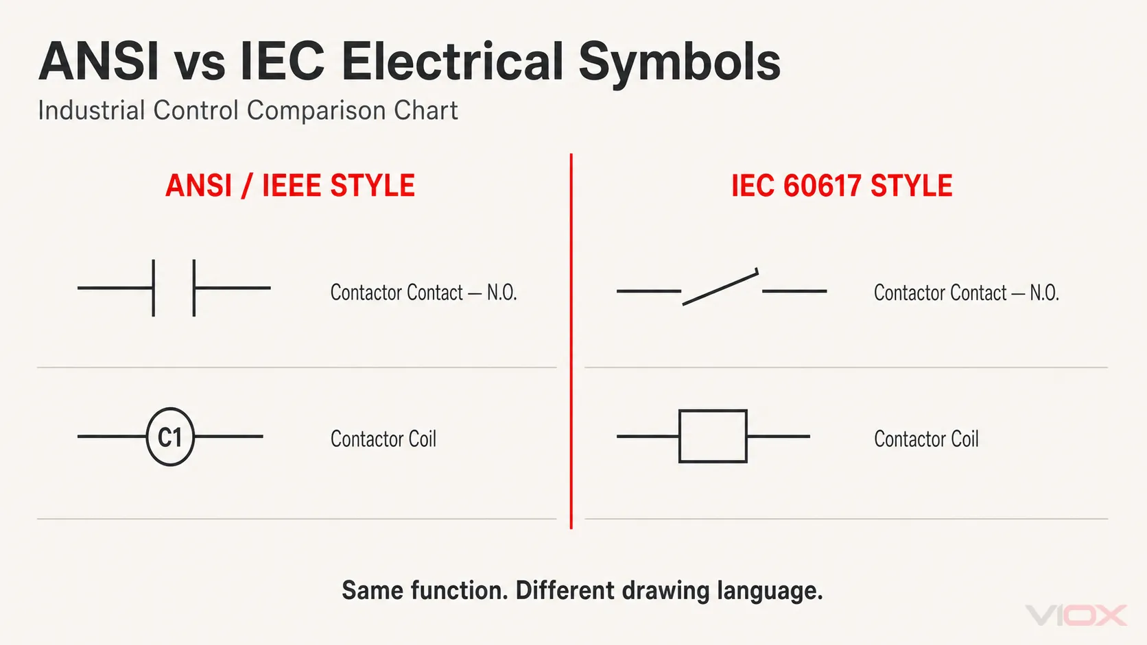
Τα ηλεκτρικά σύμβολα είναι γραφικά σήματα που χρησιμοποιούνται για την αναπαράσταση εξαρτημάτων, συνδέσεων και λειτουργιών σε σχηματικά διαγράμματα και διαγράμματα ελέγχου. Η ίδια ηλεκτρική λειτουργία μπορεί να φαίνεται διαφορετική ανάλογα με τη σύμβαση σχεδίασης: ένα πηνίο επαφέα μπορεί να εμφανίζεται ως κύκλος σε ένα κοινό σχέδιο τύπου ANSI/IEEE και ως ορθογώνιο σε ένα σχέδιο τύπου IEC.
Αυτό το διάγραμμα ηλεκτρικών συμβόλων συγκρίνει 29 κοινώς συναντώμενα σύμβολα βιομηχανικού ελέγχου σε δύο στήλες: στυλ ANSI/IEEE και στυλ IEC 60617. Καλύπτει επαφές, χρονικές επαφές, συσκευές χειρισμού, διακόπτες διεργασιών, πηνία, ενεργοποιητές, συσκευές σηματοδότησης, ακροδέκτες, αυτόματους διακόπτες και ασφάλειες.
Χρησιμοποιήστε το διάγραμμα για να αναγνωρίσετε μια οικογένεια συμβόλων και, στη συνέχεια, επιβεβαιώστε το υπόμνημα του έργου, την ετικέτα της συσκευής, τους αριθμούς ακροδεκτών και την ισχύουσα τεκμηρίωση πριν από την καλωδίωση ή τη συντήρηση του εξοπλισμού.
Τι περιλαμβάνει αυτό το διάγραμμα ηλεκτρικών συμβόλων
| Κατηγορία | Σύμβολα που καλύπτονται | Πλήθος |
|---|---|---|
| Βασικές επαφές | Contactor N.O./N.C.; control relay N.O./N.C. | 4 |
| Επαφές χρονικού | Επαφές κανονικά ανοικτές (N.O.)/κανονικά κλειστές (N.C.) με καθυστέρηση ενεργοποίησης και καθυστέρηση απενεργοποίησης | 4 |
| Συσκευές χειρισμού | Επιλογέας· μπουτόν κανονικά ανοικτής (NO) / κανονικά κλειστής (NC) επαφής· μπουτόν τύπου μανιταριού | 4 |
| Αισθητήρες και διακόπτες διεργασιών | Διακόπτες στάθμης υγρών, ροής, πίεσης, θερμοκρασίας, ορίου και προσέγγισης | 6 |
| Πηνία και ενεργοποιητές | Ρελέ ελέγχου, επαφέας, εκκινητής κινητήρα, χρονικό ρελέ, ηλεκτρομαγνητική βαλβίδα και μετρητής | 6 |
| Σήμα, σύνδεση και προστασία | Ενδεικτική λυχνία, φις/πρίζα, ακροδέκτες, αυτόματος διακόπτης και ασφάλεια | 5 |
| Σύνολο | 29 |
Το διάγραμμα εστιάζει σκόπιμα σε σχέδια βιομηχανικού ελέγχου και πινάκων χαμηλής τάσης. Τα σύμβολα ηλεκτρονικών εξαρτημάτων, όπως τρανζίστορ, τελεστικοί ενισχυτές και λογικές πύλες, ανήκουν σε διαφορετική πρόθεση αναζήτησης και δεν περιλαμβάνονται εδώ.
Διαβάστε τέσσερα στοιχεία μαζί: Σύμβολο, Ετικέτα, Ακροδέκτης και Κατάσταση
Ένα σύμβολο σπάνια παρέχει επαρκείς πληροφορίες από μόνο του. Η ακριβής ερμηνεία των σχεδίων εξαρτάται από τέσσερα ξεχωριστά επίπεδα.
| Στοιχείο σχεδίου | Τι σας λέει | Παράδειγμα |
|---|---|---|
| Γραφικό σύμβολο | Λειτουργία συσκευής ή ενέργεια επαφής | Πηνίο, επαφή NO, ασφάλεια, αυτόματος διακόπτης |
| Προσδιορισμός αναφοράς | Σε ποια συσκευή ανήκει το σύμβολο | Ένα έργο μπορεί να χρησιμοποιεί CR, KM, KA, QF ή άλλο σύστημα ετικετών |
| Σήμανση ακροδεκτών | Πού συνδέονται οι αγωγοί στη φυσική συσκευή | A1/A2, 13/14, 21/22 ή ακροδέκτες συγκεκριμένου κατασκευαστή |
| Κανονική κατάσταση και σημειώσεις | Η κατάσταση στην οποία σχεδιάζεται το σύμβολο | Χωρίς τάση, μη ενεργοποιημένη, χωρίς πίεση ή άλλη καθορισμένη κατάσταση ηρεμίας |
Οι προσδιορισμοί αναφοράς δεν αποτελούν απλώς μέρος του συμβόλου. Η δομή τους μπορεί να ακολουθεί μια εταιρική σύμβαση, μια περιφερειακή πρακτική ή ένα σύστημα βασισμένο στη σειρά IEC 81346. Εάν ένα ακρωνύμιο δεν είναι οικείο, χρησιμοποιήστε το υπόμνημα του έργου και το VIOX αναφορά με πλήρεις ηλεκτρολογικούς όρους αντί να μαντεύετε μόνο από τα γράμματα.
Βασικά σύμβολα επαφών: N.O. και N.C.
Οι επαφές κανονικά ανοικτή (N.O.) και κανονικά κλειστή (N.C.) εμφανίζονται συνήθως στην καθορισμένη κατάσταση ηρεμίας τους. Για έναν κοινό επαφέα ή ρελέ, αυτό σημαίνει συνήθως ότι το πηνίο δεν φέρει τάση και ο ενεργοποιητής δεν λειτουργεί.
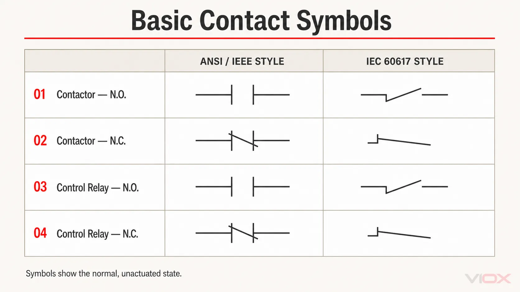
Το γραφικό σχήμα προσδιορίζει την κατάσταση της επαφής, αλλά δεν προσδιορίζει πάντα την πλήρη φυσική συσκευή. Μια βοηθητική επαφή επαφέα και μια επαφή ρελέ ελέγχου μπορεί να χρησιμοποιούν την ίδια βασική γεωμετρία επαφής. Η ετικέτα αναφοράς συνδέει αυτή την επαφή με το σωστό πηνίο ή συσκευή σε άλλο σημείο του σχεδίου.
Για επαφές μεταγωγής με περισσότερους από έναν πόλους, δείτε τον ξεχωριστό οδηγό συμβόλων ρελέ SPDT έναντι DPDT.
Σύμβολα χρονικών επαφών: Καθυστέρηση ενεργοποίησης (ON-Delay) έναντι καθυστέρησης απενεργοποίησης (OFF-Delay)
Οι χρονικές επαφές προσθέτουν μια χρονικά εξαρτώμενη ενέργεια στην κανονική κατάσταση της επαφής:
- Καθυστέρηση ενεργοποίησης (ON-delay): η χρονική ενέργεια πραγματοποιείται αφού ενεργοποιηθεί η είσοδος χρονισμού ή το πηνίο.
- Καθυστέρηση απενεργοποίησης (OFF-delay): η χρονική ενέργεια πραγματοποιείται αφού αφαιρεθεί το σήμα έναρξης ή αλλάξει η κατάσταση χρονισμού, ανάλογα με τον σχεδιασμό της συσκευής.
- N.O. ή N.C.: περιγράφει την κανονική κατάσταση της επαφής, όχι την κατεύθυνση της καθυστέρησης.
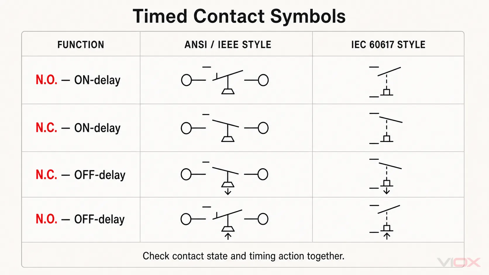
Να ερμηνεύετε πάντα την κατάσταση της επαφής και το σήμα χρονισμού μαζί. Ένα διάγραμμα συμβόλων δεν μπορεί να σας υποδείξει το πραγματικό εύρος καθυστέρησης, τη συμπεριφορά επαναφοράς, τη μέθοδο ενεργοποίησης ή τη διάταξη τροφοδοσίας. Αυτές οι λεπτομέρειες προκύπτουν από το διάγραμμα της συσκευής και το φύλλο δεδομένων. Ο οδηγός της VIOX για χρονικά ρελέ εξηγεί πώς το σύμβολο σχετίζεται με τη χρονική καθυστέρηση ενεργοποίησης (on-delay), απενεργοποίησης (off-delay) και άλλες λειτουργίες χρονοδιακόπτη.
Σύμβολα επιλογέων και μπουτόν
Τα σύμβολα των συσκευών χειρισμού συνδυάζουν μια κατάσταση επαφής με έναν χειροκίνητο ενεργοποιητή. Το παρακάτω διάγραμμα συγκρίνει επιλογείς, κανονικά ανοικτά και κανονικά κλειστά μπουτόν, καθώς και ένα γενικό μπουτόν τύπου μανιταριού.
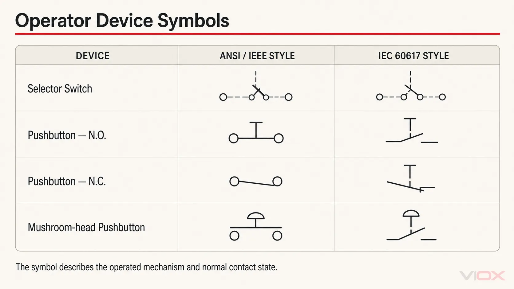
Ένας ενεργοποιητής σε σχήμα μανιταριού δεν αποδεικνύει αυτόματα ότι μια συσκευή είναι διακόπτης έκτακτης ανάγκης. Οι λειτουργίες έκτακτης ανάγκης απαιτούν τη σωστή συσκευή, ενέργεια επαφής, αρχιτεκτονική ασφαλείας, σήμανση και τις ισχύουσες απαιτήσεις μηχανημάτων. Διαβάζετε το σύμβολο μαζί με τις σημειώσεις ασφαλείας και την τεκμηρίωση του εξοπλισμού αντί να προσδιορίζετε τη λειτουργία μόνο από το σχήμα του ενεργοποιητή.
Σύμβολα αισθητήρων και διακοπτών διεργασιών
Οι διακόπτες διεργασιών και θέσης χρησιμοποιούν ένα σύμβολο επαφής συν ένα προσδιοριστικό ή σήμα ενεργοποιητή που υποδεικνύει τι λειτουργεί την επαφή. Τα έξι παραδείγματα παρακάτω καλύπτουν τη μεταγωγή στάθμης υγρού, ροής, πίεσης, θερμοκρασίας, ορίου και εγγύτητας.
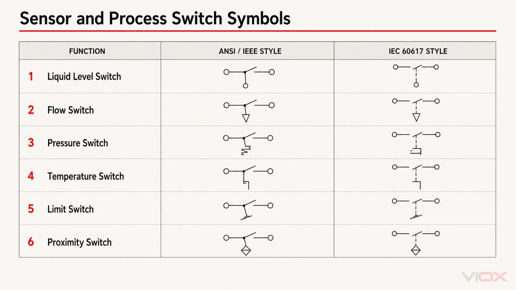
Κατά την ανάγνωση αυτών των συμβόλων, θέστε δύο ερωτήματα:
- Ποια φυσική μεταβλητή ή κίνηση λειτουργεί τον διακόπτη;
- Ποια είναι η κατάσταση της επαφής υπό την καθορισμένη κανονική συνθήκη του σχεδίου;
Το σχέδιο θα πρέπει επίσης να προσδιορίζει το σημείο ρύθμισης (setpoint), τη θέση της συσκευής, τη συνθήκη διεργασίας ή την παραπομπή, όταν αυτές οι πληροφορίες είναι απαραίτητες. Το σύμβολο από μόνο του δεν ορίζει το εύρος βαθμονόμησης, την τεχνολογία ανίχνευσης, τον τύπο εξόδου ή την περιβαλλοντική κατάταξη.
Σύμβολα πηνίων και ενεργοποιητών
Τα πηνία μετατρέπουν μια ηλεκτρική είσοδο σε μεταγωγή ή μηχανική δράση. Στα κοινά σχέδια ελέγχου της Βόρειας Αμερικής, ένα πηνίο ρελέ ή επαφέα αναπαρίσταται συχνά από έναν κύκλο με ετικέτα. Τα σχέδια τύπου IEC χρησιμοποιούν συνήθως ένα ορθογώνιο, με ένα προσδιοριστικό όταν η συσκευή έχει μια συγκεκριμένη δράση, όπως χρονισμό ή λειτουργία σωληνοειδούς.
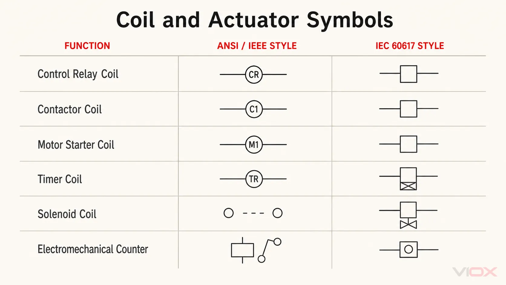
Το πηνίο και οι επαφές του ενδέχεται να εμφανίζονται σε διαφορετικές σελίδες ή σε διαφορετικά σκαλοπάτια του διαγράμματος ladder. Αντιστοιχίστε τα χρησιμοποιώντας τον προσδιορισμό αναφοράς και τις πληροφορίες διασταυρούμενης αναφοράς. Μην υποθέτετε ότι δύο πηνία με παρόμοιο σχήμα ανήκουν στην ίδια συσκευή.
Σύμβολα σήματος, σύνδεσης και προστασίας
Η τελευταία ομάδα καλύπτει συσκευές που υποδεικνύουν την κατάσταση, συνδέουν αγωγούς ή διακόπτουν το μη φυσιολογικό ρεύμα.
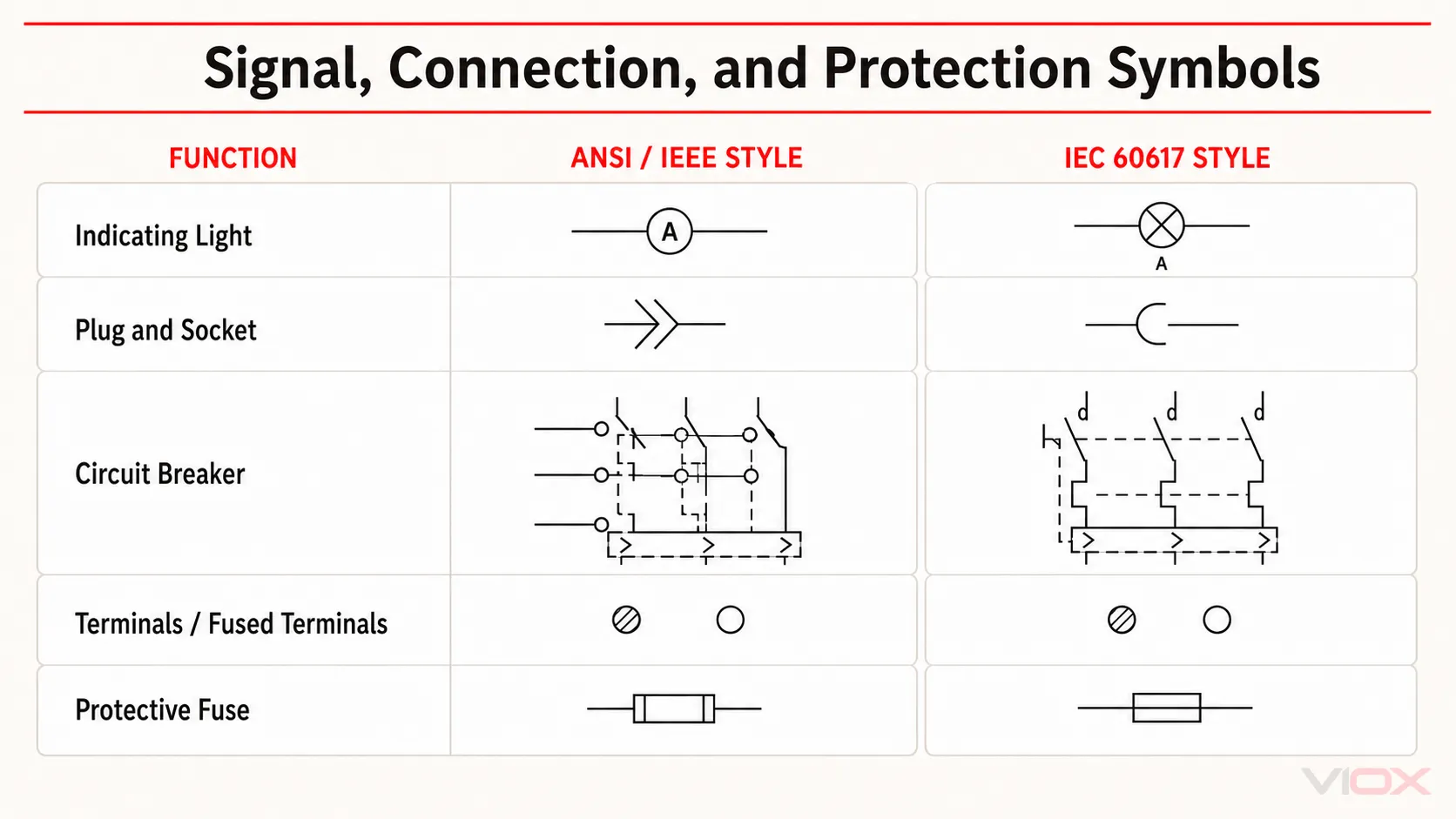
Τα σημαντικά όρια περιλαμβάνουν:
- Ένα ενδεικτική λυχνία το σύμβολο δείχνει μια λειτουργία σηματοδότησης· η τάση, το χρώμα και η τεχνολογία της λυχνίας απαιτούν ξεχωριστή τεκμηρίωση.
- A φις και πρίζα το σύμβολο υποδεικνύει μια αποσπώμενη σύνδεση, όχι τη φυσική σειρά του συνδετήρα ή τη διάταξη των ακίδων.
- A σύμβολο ακροδέκτη προσδιορίζει ένα σημείο σύνδεσης· η αρίθμηση του ακροδέκτη και το αν είναι ασφαλισμένος πρέπει να επιβεβαιώνονται από το σχέδιο και τον πίνακα υλικών.
- A διακόπτης κυκλώματος το σύμβολο προσδιορίζει μια λειτουργία διακοπής και προστασίας, αλλά δεν αναφέρει την ονομαστική τιμή, την καμπύλη απόζευξης, την ικανότητα διακοπής ή την πιστοποίηση του αυτόματου διακόπτη.
- A σύμβολο ασφάλειας δεν προσδιορίζει από μόνο του την κατηγορία ταχύτητας ή την κατηγορία εφαρμογής. Για αυτές τις διακρίσεις, χρησιμοποιήστε το λεπτομερές οδηγό ηλεκτρικών συμβόλων ασφαλειών.
Στυλ ANSI/IEEE έναντι στυλ IEC 60617
Οι δύο στήλες πρέπει να αντιμετωπίζονται ως γλώσσες σχεδίασης και όχι ως ανταγωνιστικά επίπεδα ποιότητας.
| Σημείο | Σχέδια τύπου ANSI/IEEE | IEC 60617-style drawings |
|---|---|---|
| Τυπικό πλαίσιο | Τεκμηρίωση βιομηχανικού ελέγχου της Βόρειας Αμερικής και παλαιότερες βιβλιοθήκες σχεδίων | Διεθνή ηλεκτροτεχνικά διαγράμματα και τεκμηρίωση μηχανημάτων με εξαγωγικό προσανατολισμό |
| Κοινή οπτική διαφορά | Τα πηνία είναι συχνά κυκλικά και ενδέχεται να περιέχουν μια συντομογραφία της συσκευής | Τα πηνία είναι συνήθως ορθογώνια, με ξεχωριστούς προσδιοριστές όπου χρειάζεται |
| Ταυτοποίηση συσκευής | Συχνά χρησιμοποιεί γνωστές συντομογραφίες της Βόρειας Αμερικής ή ετικέτες ειδικές για το έργο | Μπορεί να χρησιμοποιεί ετικέτες προσανατολισμένες στο πρότυπο IEC ή ένα σύστημα προσδιορισμού αναφοράς IEC 81346 |
| Τελική αρχή | Υπόμνημα έργου, εφαρμοστέα τεκμηρίωση και υιοθετημένη πρακτική εταιρείας/κλάδου | Υπόμνημα έργου και η βάση δεδομένων IEC 60617 ή το υιοθετημένο πρότυπο έργου |
Το Βάση δεδομένων IEC 60617 είναι η επίσημη πηγή του IEC για γραφικά σύμβολα που χρησιμοποιούνται σε ηλεκτροτεχνικά διαγράμματα. Περιέχει πολύ περισσότερα σύμβολα και μεταδεδομένα εφαρμογής από όσα μπορούν να χωρέσουν σε έναν πρακτικό πίνακα ιστολογίου.
Το IEEE/ANSI 315-1975 εξακολουθεί να αναφέρεται ευρέως σε παλαιότερες βιβλιοθήκες και εκπαιδευτικό υλικό, αλλά το IEEE το καταχωρεί επί του παρόντος ως Ανενεργό-Δεσμευμένο. Για τον λόγο αυτό, το παρόν άρθρο χρησιμοποιεί τον περιορισμένο όρο στυλ ANSI/IEEE αντί να ισχυρίζεται ότι κάθε γραφικό στην αριστερή στήλη αποτελεί τρέχουσα καθολική απαίτηση ANSI. Πάντα να επαληθεύετε τι απαιτεί πραγματικά η σύμβαση, ο πελάτης, η αρχή ή το πρότυπο σχεδίασης της εταιρείας.
Πώς να διαβάζετε ένα βιομηχανικό ηλεκτρολογικό σχέδιο
Χρησιμοποιήστε αυτή τη σειρά αντί να ερμηνεύετε μεμονωμένα σύμβολα ένα προς ένα.
1. Διαβάστε το πλαίσιο τίτλου και το υπόμνημα
Επιβεβαιώστε τον τύπο του σχεδίου, την αναθεώρηση, την ισχύουσα σύμβαση, το σύστημα τάσης και τη λίστα συντομογραφιών. Εάν το σχέδιο περιλαμβάνει υπόμνημα ειδικό για το έργο, αυτό υπερισχύει των υποθέσεων που βασίζονται σε έναν γενικό πίνακα.
2. Προσδιορίστε τον τύπο του σχεδίου
- A σχηματικό δίνει έμφαση στην ηλεκτρική λειτουργία και τη λογική ελέγχου.
- A διάγραμμα καλωδίωσης δίνει έμφαση στα σημεία φυσικής σύνδεσης και στη δρομολόγηση των αγωγών.
- A μονογραμμικό διάγραμμα απλοποιεί ένα σύστημα ισχύος πολλών αγωγών σε μια λειτουργική επισκόπηση.
- A διάταξη πίνακα δείχνει τη φυσική τοποθέτηση και δεν αντικαθιστά το σχηματικό διάγραμμα.
3. Καθορισμός της Κανονικής Κατάστασης
Προσδιορίστε εάν το σχέδιο ορίζει τις συσκευές ως απενεργοποιημένες, χωρίς πίεση, σε ηρεμία ή σε άλλη κανονική κατάσταση. Αυτό είναι απαραίτητο κατά την ερμηνεία των επαφών NO/NC, των πιεζοστατών, των τερματικών διακοπτών και των χρονικών επαφών.
4. Διαχωρίστε τις διαδρομές ισχύος και ελέγχου
Ακολουθήστε την κύρια διαδρομή ισχύος μέσω της απομόνωσης, της προστασίας, της μεταγωγής και του φορτίου. Στη συνέχεια, εντοπίστε τη διαδρομή ελέγχου μέσω μπουτόν, διατάξεων αλληλομανδάλωσης, επαφών ρελέ, πηνίων, αισθητήρων και ενδείξεων.
5. Αντιστοιχίστε τα πηνία με τις επαφές
Χρησιμοποιήστε ετικέτες και διασταυρούμενες αναφορές για να βρείτε κάθε επαφή που λειτουργεί μέσω πηνίου ρελέ, επαφέα, εκκινητή ή χρονικού ρελέ. Η φυσική εγγύτητα στη σελίδα δεν αποδεικνύει ότι τα σύμβολα ανήκουν στην ίδια συσκευή.
6. Επαληθεύστε τους ακροδέκτες πριν από τη συνδεσμολογία
Το σχηματικό διάγραμμα εξηγεί τη λειτουργία· το διάγραμμα ακροδεκτών του κατασκευαστή επιβεβαιώνει τα πραγματικά σημεία σύνδεσης. Ελέγξτε τη σήμανση της συσκευής, το φύλλο δεδομένων, τους αριθμούς καλωδίων, το πλάνο ακροδεκτών και τη λίστα υλικών πριν από την πραγματοποίηση αλλαγών.
Για ελέγχους κατά το στάδιο θέσης σε λειτουργία, χρησιμοποιήστε τον οδηγό VIOX για λάθη ηλεκτρικού πίνακα πριν από την ενεργοποίηση.
Συνηθισμένα λάθη κατά την ανάγνωση ηλεκτρικών συμβόλων
- Αντιμετωπίζοντας ένα διάγραμμα ως οδηγία καλωδίωσης: μια σύγκριση συμβόλων δεν παρέχει αναθέσεις ακροδεκτών ή ονομαστικά χαρακτηριστικά προϊόντος.
- Υποθέτοντας ότι οι ετικέτες είναι καθολικές: οι ονομασίες KM, KA, CR, QF και παρόμοιες εξαρτώνται από το επιλεγμένο σύστημα αναφοράς και την πρακτική του έργου.
- Ανάγνωση επαφών στην κατάσταση λειτουργίας: τα περισσότερα σύμβολα επαφών σχεδιάζονται σε μια καθορισμένη κανονική κατάσταση.
- Αποκαλώντας κάθε συσκευή με κεφαλή μανιταριού διακόπτη έκτακτης ανάγκης: το σχήμα του ενεργοποιητή από μόνο του δεν καθορίζει τη λειτουργία ασφαλείας.
- Σύγχυση μεταξύ ενός σχηματικού διαγράμματος και μιας διάταξης πίνακα: οι λειτουργικές σχέσεις δεν δείχνουν την ακριβή θέση τοποθέτησης ή τη διαδρομή των καλωδίων.
- Αγνόηση του υπομνήματος όταν αναμιγνύονται στυλ: ο εισαγόμενος εξοπλισμός και τα τροποποιημένα σχέδια ενδέχεται να περιέχουν περισσότερες από μία συμβάσεις.
ΣΥΧΝΈΣ ΕΡΩΤΉΣΕΙΣ
Τι είναι ένας πίνακας ηλεκτρικών συμβόλων;
Ένας πίνακας ηλεκτρικών συμβόλων ομαδοποιεί γραφικά σήματα που χρησιμοποιούνται για την αναπαράσταση συσκευών και λειτουργιών σε σχηματικά διαγράμματα. Ένας χρήσιμος πίνακας προσδιορίζει επίσης τη σύμβαση σχεδίασης και εξηγεί πώς τα σύμβολα σχετίζονται με ετικέτες, ακροδέκτες και κανονικές καταστάσεις.
Είναι τα ηλεκτρικά σύμβολα ANSI και IEC τα ίδια;
Όχι πάντα. Ορισμένες λειτουργίες φαίνονται παρόμοιες, ενώ άλλες—ειδικά τα πηνία, οι επαφές, οι χρονικές διατάξεις και οι μηχανισμοί χειρισμού—ενδέχεται να σχεδιάζονται διαφορετικά. Το υπόμνημα του έργου και η ισχύουσα τεκμηρίωση παραμένουν η τελική αρχή.
Τι είναι το IEC 60617;
Το IEC 60617 είναι η βάση δεδομένων του IEC με γραφικά σύμβολα για ηλεκτροτεχνικά διαγράμματα. Καλύπτει αγωγούς, εξαρτήματα, διακόπτες ισχύος, διατάξεις ελέγχου, προστατευτικές διατάξεις, όργανα, διατάξεις σηματοδότησης και άλλες κατηγορίες.
Ποια είναι η διαφορά μεταξύ του IEC 60617 και του IEC 81346;
IEC 60617 addresses graphical symbols used in diagrams. The IEC 81346 series addresses system structuring, object classification, and reference designations. A drawing may therefore use an IEC 60617-style symbol and a separate IEC 81346-based device identifier.
Γιατί μια επαφή επαφέα και μια επαφή ρελέ μπορεί να φαίνονται ίδιες;
Το σύμβολο της επαφής περιγράφει την κατάσταση μεταγωγής και τη λειτουργία. Το σχετικό πηνίο, ο προσδιορισμός αναφοράς, το πλαίσιο του κυκλώματος και η τεκμηρίωση προσδιορίζουν εάν η επαφή ανήκει σε επαφέα, ρελέ ελέγχου, χρονικό ρελέ ή άλλη συσκευή.
Πώς μπορώ να καταλάβω αν μια επαφή είναι κανονικά ανοικτή ή κανονικά κλειστή;
Αρχικά προσδιορίστε την κανονική κατάσταση του σχεδίου. Μια επαφή NO είναι ανοικτή σε αυτή την κατάσταση· μια επαφή NC είναι κλειστή. Μην εξάγετε συμπεράσματα για την κανονική κατάσταση από τη λειτουργική κατάσταση του εξοπλισμού.
Μπορώ να συνδέσω ένα εξάρτημα χρησιμοποιώντας μόνο το σχηματικό του σύμβολο;
Όχι. Χρησιμοποιήστε το σχηματικό για να κατανοήσετε τη λειτουργία και, στη συνέχεια, επαληθεύστε τις σημάνσεις των ακροδεκτών, την τάση, τη διάταξη των επαφών, τις ονομαστικές τιμές και τις οδηγίες σύνδεσης από την τεκμηρίωση του προϊόντος.
Είναι το IEEE/ANSI 315 ακόμα ενεργό πρότυπο;
Το IEEE καταχωρεί το IEEE/ANSI 315-1975 ως ανενεργό-δεσμευμένο (Inactive-Reserved). Οι γραφικές συμβάσεις του παραμένουν κοινές στην παλαιότερη και στη βορειοαμερικανική τεκμηρίωση, αλλά οι τρέχουσες απαιτήσεις του έργου θα πρέπει να επαληθεύονται και όχι να θεωρούνται δεδομένες.
Πηγές και Τεχνικές Αναφορές
- IEC 60617: Γραφικά σύμβολα για διαγράμματα
- IEEE/ANSI 315-1975 κατάσταση και πεδίο εφαρμογής
- IEC 81346-1:2022—βασικοί κανόνες για προσδιορισμούς αναφοράς
- IEC 81346-2:2019—ταξινόμηση αντικειμένων και κωδικοί κλάσης
- NFPA 79: Ηλεκτρικό πρότυπο για βιομηχανικά μηχανήματα
- Τεχνική αναφορά συμβόλων ANSI και IEC της c3controls
Αυτό το διάγραμμα αποτελεί έναν πρακτικό πόρο αναγνώρισης και όχι υποκατάστατο για εγκεκριμένα πρότυπα, προδιαγραφές έργου ή οδηγίες καλωδίωσης του κατασκευαστή.