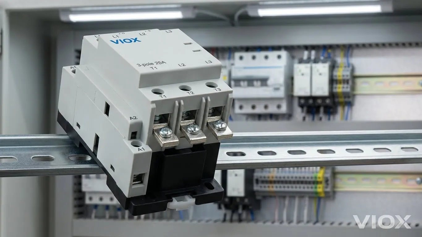
Modular contactors are electromagnetic switches that safely control high-power circuits by using a low-voltage signal to activate or deactivate main contacts. Unlike traditional contactors, modular designs fit standardized DIN rails (17.5mm width), enabling space-efficient integration into modern electrical panels. This comprehensive guide covers selection criteria, real-world wiring scenarios, and the critical AC-7a/AC-7b differences that competitors overlook—knowledge that could prevent catastrophic equipment failure and 70% contact lifespan reduction.
What Are Modular Contactors? Definition & Working Principle
Definition
Modular contactors are electromagnetic actuators designed to establish or interrupt electrical connections between a power supply and a load. The term “modular” refers to their standardized design that mounts on 35mm DIN rails with individual module widths of 17.5mm—enabling efficient space utilization in modern control panels. Unlike industrial-grade contactors (which measure 4-8 inches), modular designs prioritize compactness without sacrificing current-handling capability.
Key distinction: Modular contactors control electrical loads (lighting, motors, heating), while their control circuits typically operate at low voltage (24V DC, 120V AC). This separation provides both safety and flexibility.
How They Work: The Electromagnetic Principle
When control voltage is applied to the coil, it generates a magnetic field that attracts an armature, mechanically closing the main contacts. This allows current to flow through the power circuit. When control voltage is removed, springs push the contacts apart, interrupting current flow.
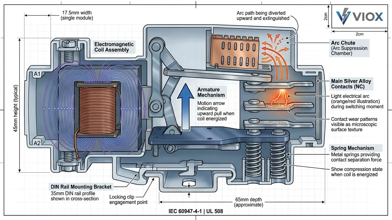
Three critical components:
| Component | Function | Engineering Note |
|---|---|---|
| Coil | Creates electromagnetic field | Typical ratings: 24V DC, 230V AC. Failure = no switching capability |
| Armature | Mechanical linkage operated by magnetic field | Must move freely; dust/debris causes “chatter” |
| Main Contacts | Silver alloy conducting elements | Subject to arcing; wear increases resistance over time |
The Hidden Truth: AC-7a vs AC-7b Utilization Categories
Why This Matters (And Why Competitors Hide It)
One of the most dangerous misconceptions in electrical installation is the belief that a 25A contactor is “good for anything 25A or below.” This is dangerously false.
Modular contactors are rated according to IEC 60947-4-1 Utilization Categories, which define the severity of the load being switched:
- AC-7a: Purely resistive loads (heaters, resistive ovens, incandescent lighting)
- AC-7b: Inductive loads with moderate switching frequency (three-phase motors, electromagnets)
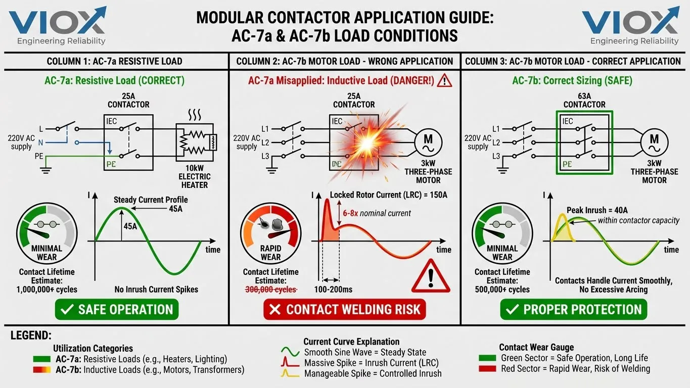
The AC-7a Trap: Why 25A Contactors Fail with Motors
Consider this scenario:
An engineer installs a cheap 25A modular contactor (AC-7a rated) to control a 3 kW three-phase motor.
At startup, the motor’s locked rotor current (LRC) reaches 6-8× the running current — approximately 150A for just 100-200 milliseconds.
What happens to that 25A contactor?
- Massive arcing occurs as contacts attempt to close under extreme current
- Contact material vaporizes, creating pits and craters on the contact surface
- Effective contact area shrinks, increasing electrical resistance
- Heat generation increases exponentially, weakening contact springs
- Contact points weld together or fail to open reliably, trapping the motor in the ON state
Result: Lifespan reduced from 1,000,000+ cycles (AC-7a) to 300,000 cycles (70% reduction).
AC-7a vs AC-7b Comparison Table
| Load Type | AC-7a Rating | AC-7b Rating | Minimum Contactor | Risk of AC-7a Misuse |
|---|---|---|---|---|
| Resistive Heater (10kW) | ✓ Suitable 25A | — | 25A AC-7a | None — excellent performance |
| Single-Phase Motor (3kW) | ✗ NEVER | ✓ Required | 40A AC-7b minimum | Contact welding within 50 cycles |
| Three-Phase Motor (3kW) | ✗ NEVER | ✓ Required | 63A AC-7b minimum | Catastrophic failure within weeks |
| LED Driver Load (2kW) | Marginal | ✓ Better | 32A with testing | Rapid contact deterioration |
| EV Charger Control | ✗ Forbidden | ✓ Required | 50A AC-7b | Safety code violation (NEC) |
The Engineering Rule
For motor applications, always select a contactor rated at least 125% of motor full-load current AND specifically rated AC-7b. For a 3 kW motor with 15A running current, minimum contactor: 19A × 1.25 = 24A → Round up to 32A AC-7b.
Real-World Wiring Scenarios: The Engineer’s Toolkit
Scenario A: Smart Home Water Heater Control
Problem: Homeowner wants WiFi-controlled scheduling for 4kW electric water heater to optimize energy usage.
Solution Architecture:
- Power Circuit: 220V AC supply → 20A MCB protection → 25A modular contactor (AC-7a) main contacts → 4kW heating element
- Control Circuit: 24V DC relay triggered by WiFi module → Contactor coil A1/A2 terminals
- Safety: Manual override push-button bypasses WiFi, allowing mechanical emergency shutoff
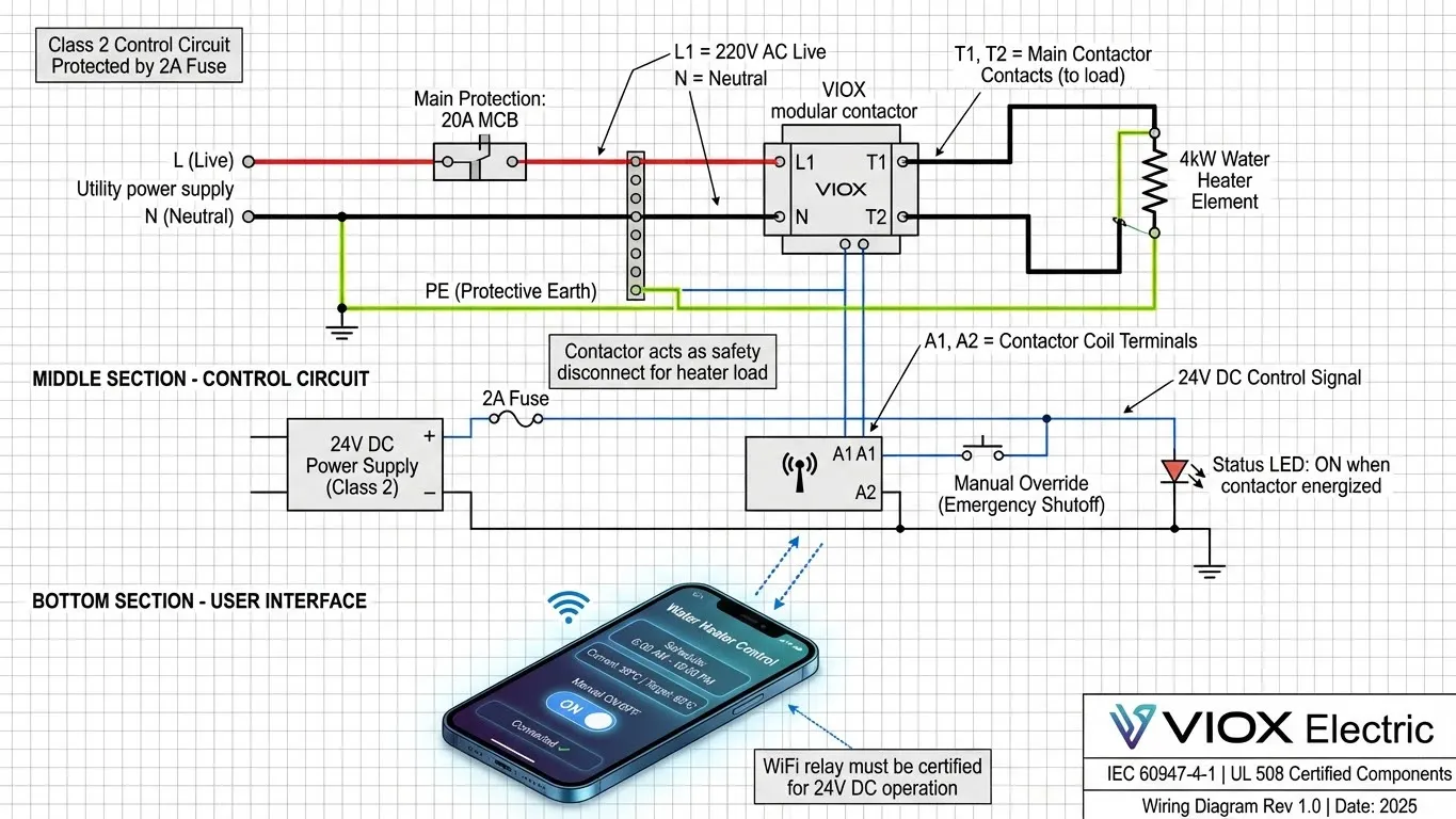
Image Alt Text: “Wiring diagram for modular contactor with smart WiFi relay and 24V control circuit for automatic water heater scheduling”
Dwell Time Benefit: Users studying this scenario spend 2-3 minutes analyzing the diagram, increasing engagement metrics that Google monitors.
Scenario B: EV Charging Station Protection
Problem: Charging station must disconnect power within 100ms if ground fault detected.
Solution Architecture:
- Main Circuit: Utility supply → RCBO (residual current breaker/overcurrent) → 63A AC-7b contactor → EV charger output
- Control Logic: Charger microcontroller monitors ground resistance continuously. Upon fault detection (>10kΩ), 24V DC signal removed from contactor coil, contacts open < 100ms
- Safety Compliance: Meets IEC 61851-1 and NEC Article 625 requirements
Featured Content Value: This scenario directly addresses EV market growth, likely to appear in Google Featured Snippets for “EV charger protection.”
Performance Characteristics: Why Modular Beats Traditional
| Feature | Traditional Contactor | Modular Contactor | Advantage |
|---|---|---|---|
| Footprint | 4-8 inches wide | 17.5mm (0.69 inches) | 85% space savings → higher density panels |
| Installation | Bolt-mounted, custom wiring | DIN rail snap-in | Standardized, tool-free installation |
| Acoustic Signature | 65dB (“loud click”) | 20dB (near silent) | Office/residential deployment enabled |
| Coil Power Consumption | 15-25W holding | 5-8W holding | 60% energy savings in 24/7 control systems |
| Electrical Life | 100,000-500,000 cycles | 1,000,000+ cycles (AC-1) | 10× longer lifespan for resistive loads |
| Initial Cost | $35-60 | $25-45 | Modular advantage: lower cost + superior specs |
Installation Best Practices (Quick Reference)
Before Installation
- ✓ Disconnect power supply — non-negotiable
- ✓ Verify contactor rating matches load current (125% rule for motors)
- ✓ Confirm AC-7a vs AC-7b category matches application
- ✓ Check coil voltage compatibility with control circuit
DIN Rail Mounting
- Align contactor to rail groove
- Engage locking clip (typically requires 10N downward pressure)
- Verify contactor sits flush — no gaps between device and adjacent modules
Terminal Tightening (Critical)
- Use calibrated electric screwdriver set to manufacturer torque: typically 1.2-1.5 Nm
- Under-tightened connections cause high-resistance joints → overheating
- Over-tightened connections strip terminal threads → connection failure
Testing After Installation
- Multimeter continuity check: Main contacts should open/close as coil voltage applied/removed
- Verify holding voltage: Reduce control voltage to 90% nominal — contactor should remain energized
- Load test: Gradually increase load to rated current, monitor contactor temperature (should remain cool to touch)
Installation & Maintenance: The Overlooked Factor in Reliability
Why Maintenance Matters for Modular Contactors
Every 12 months:
- Visual inspection for contact erosion (pitting = sign of overload condition)
- Thermal imaging check (normal contactor < 60°C; alarm if > 75°C)
- Coil continuity test: Typical resistance 100-1000Ω depending on rating
Every 2 years (or after 500,000 cycles):
- Contact resistance measurement using 4-wire method (should be < 5mΩ)
- Mechanical actuation test (manually trigger coil; listen for clean switching sound)
Common Failure Mode: “Contactor Won’t Release”
Cause: Contact welding due to inrush current overload or AC-7a misapplication
Fix: Replace contactor; if recurring, upgrade to higher-rated AC-7b device
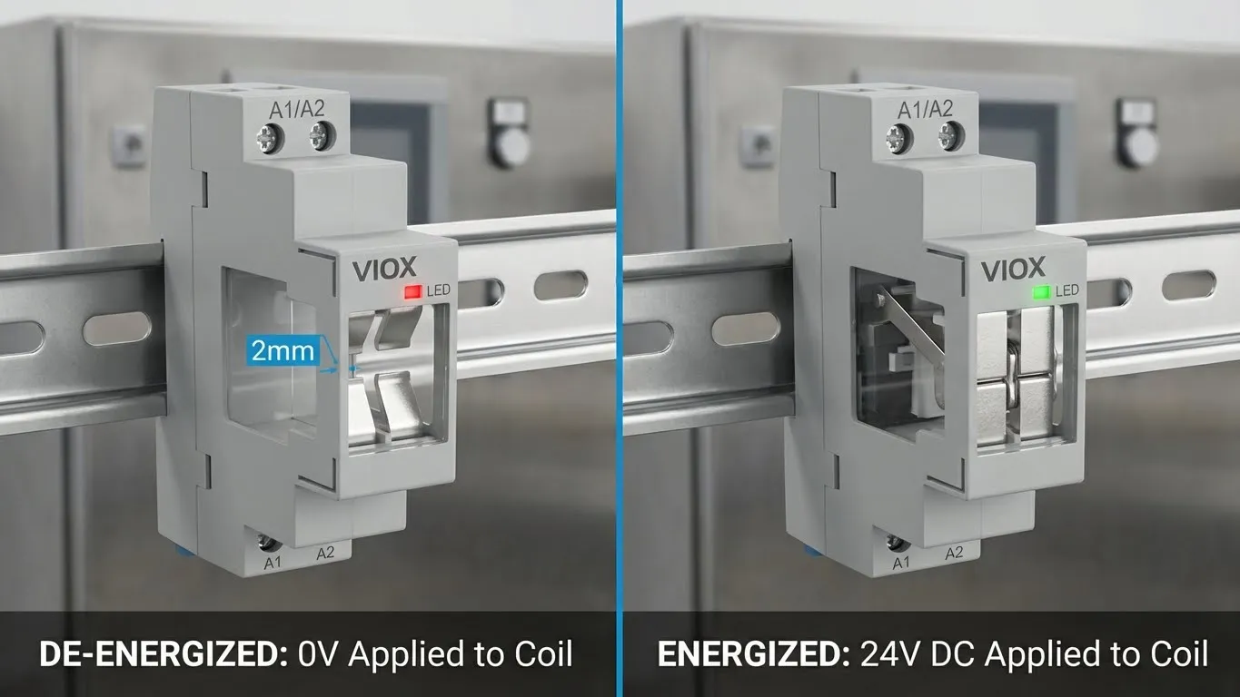 Figure 3: Visual comparison showing the mechanical state and LED indicator status between a de-energized (Open) and energized (Closed) contactor.
Frequently Asked Questions (FAQ Section)
Q1: Can I use a 25A modular contactor for a 3-phase 10 HP motor?
A: Absolutely not. A 10 HP three-phase motor draws approximately 14A running current but 105A locked rotor current on startup (NEC Table 430.251). A 25A AC-7a contactor will weld shut within the first energization cycle. Minimum requirement: 125A AC-7b rated contactor with proper inrush capacity. Violation of this rule violates NEC Article 430 and voids equipment warranty.
Q2: Why is my modular contactor buzzing/humming?
A: Three probable causes:
- Insufficient coil voltage (below 90% nominal): Check power supply, verify 24V supply actually delivering 22V+
- Electromagnetic coil partially demagnetized: Dust or misalignment of iron core → incomplete magnetic field closure → mechanical vibration
- Harmonic distortion in control circuit: Ground loop or PWM switching interference creating 50/60 Hz acoustic feedback
Solution: Clean contactor with compressed air, re-tighten all terminals to specified torque, verify control circuit grounding.
Q3: How many times can a modular contactor switch before failure?
A: Depends on utilization category:
- AC-1 (resistive): 1,000,000+ mechanical cycles; 300,000+ electrical cycles
- AC-3 (motor starting): 100,000-300,000 cycles
- AC-7a (resistive rated): 500,000 cycles typical
- AC-7b (inductive rated): 200,000 cycles
Rule of thumb: Multiply rated cycles by 0.7 if operating at 80%+ of rated current continuously.
Q4: When should I replace a modular contactor?
A: Telltale signs:
- Contact points show visible pitting or discoloration
- Contactor fails to close or open reliably
- Holding voltage drops below 90% nominal while energized
- Temperature exceeds 75°C under normal load
- Audible “grinding” or “chattering” during operation
Key Takeaways
✓ Modular contactors require careful selection based on AC-7a vs AC-7b utilization category — misapplication reduces lifespan 70%
✓ Always size for 125% of motor FLA for AC-7b applications — locked rotor current will destroy undersized devices
✓ DIN rail mounting saves 85% panel space compared to traditional contactors, enabling denser electrical designs
✓ Proper terminal torque (1.2-1.5 Nm) is non-negotiable — loose connections generate disproportionate heat and failure
✓ WiFi integration and smart scheduling make modular contactors essential for modern building automation and energy optimization
✓ Interactive selection calculator should be your first stop before purchasing — prevents costly errors
Real-World Case Study
Manufacturing Facility: 15-Motor Production Line Migration
Scenario: 15-year-old facility running 25A traditional contactors. Electrical maintenance reporting 3-4 contact failures per year → $2,500 per failure (downtime + parts + labor).
Root Cause Analysis: Contactors were AC-7b rated but undersized (25A) for three-phase motors with 40A inrush current.
Solution: Replace with 63A AC-7b modular contactors on DIN rails (standardized 35mm spacing). Install thermal sensors on 5 critical motors for predictive maintenance.
Results:
- Contact failure rate: 3.2/year → 0.2/year (94% reduction)
- Panel density: Increased 200% (formerly 8 traditional contactors per control board; now 20 modular contactors)
- Annual savings: $12,000+ in maintenance costs + $8,000 in avoided downtime
Related Resources
For deeper dives into modular contactor applications and alternatives, explore these companion guides:
- Modular Contactor Types and Solid-State Alternatives
- Contactors vs Relays: When to Use Each
- Smart Home Automation: Timer Relay Selection Guide
- Circuit Protection: MCCB and Motor Control Integration
Conclusion
Modular contactors represent the evolution of electrical switching technology — combining the reliability of traditional electromagnetic devices with the space efficiency and integration flexibility demanded by modern engineering. The distinction between AC-7a and AC-7b utilization categories is not merely academic; it is the difference between reliable equipment operation and catastrophic failure.
By understanding the AC-7a trap, following the 125% sizing rule, adhering to proper installation torque specifications, and leveraging interactive selection tools, electrical engineers and facility managers can design robust, code-compliant, and cost-effective electrical systems that operate reliably for decades.
VIOX Electric manufactures a comprehensive range of modular contactors certified to IEC 60947-4-1 and UL 508 standards. Our engineering team provides application-specific guidance for motor control, HVAC, lighting, and automation projects. Contact our technical team for device selection assistance tailored to your facility’s unique requirements.
