핵심 답변: 모듈형 접촉기란 무엇인가?
모듈형 접촉기는 조명, 난방, 환기, 펌프, 소형 모터, 전기차 충전기 보조 회로 및 빌딩 자동화 부하를 제어하는 데 사용되는 DIN 레일 장착형 전자기 스위칭 장치입니다. 일반적인 접촉기와 동일한 방식으로 작동합니다. 코일에 전원이 공급되면 주 접점이 닫히거나 열리면서 부하를 전환합니다. 차이점은 모듈형 접촉기는 배전반, 분전반 및 DIN 레일 제어반을 위해 설계된 소형 모듈 형식을 사용한다는 것입니다.
많은 카탈로그 및 IEC 61095 문맥에서 이러한 유형의 제품은 다음과 같이 설명되기도 합니다. 가정용 접촉기 또는 가정용 및 유사한 용도의 접촉기. 그러나 제품 검색 및 소싱 시에는, 모듈형 접촉기 그리고 DIN 레일 모듈형 접촉기 일반적으로 더 정확한 제품 용어입니다.
가장 중요한 선정 기준은 정격 전류, 극수, 코일 전압, 접점 구성, AC-7a 또는 AC-7b와 같은 사용 범주, 배선 레이아웃, 소음 수준, 그리고 보조 모듈이나 스마트 제어 장치와의 호환성입니다.
실제 프로젝트를 위해 모듈형 접촉기를 선정할 때, 전면에 인쇄된 암페어 정격만 보고 선택하지 마십시오. 부하 유형은 전류만큼이나 중요합니다.


모듈형 접촉기 한눈에 보기
| 항목 | 모듈 접촉기 | 표준 AC 접촉기 |
|---|---|---|
| 마운팅 | DIN 레일 모듈식 형식 | DIN 레일 또는 패널 장착 |
| 일반적인 설치 위치 | 배전반, 분전반, 소형 자동화 패널 | Industrial control cabinet, motor starter panel, machine panel |
| 일반적인 부하 | Lighting, heating, small motors, fans, pumps, building automation | Motors, industrial machines, pumps, compressors, production equipment |
| Noise profile | Often designed for quieter switching in building environments | Switching sound is usually less important in industrial panels |
| Load category focus | AC-7a and AC-7b are often important | AC-1, AC-3, AC-4 및 기타 IEC 60947 범주는 종종 중요합니다. |
| 표준 컨텍스트 | IEC 61095는 일반적으로 가정용 및 유사한 모듈형 접촉기와 관련이 있습니다. | IEC 60947-4-1은 일반적으로 산업용 접촉기 및 모터 스타터와 관련이 있습니다. |
| 가장 적합 | 모듈형 배전반 내부의 소형 스위칭 | 더 무거운 부하의 산업용 모터 및 기계 제어 |
제품 평가를 위해서는 VIOX를 참조하십시오. 모듈 접촉기 그리고 모듈 접촉기 제조업체 페이지.
모듈형 접촉기는 어떻게 작동합니까?
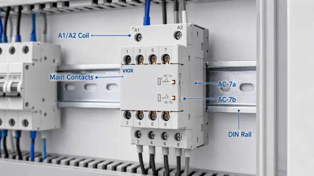
모듈형 접촉기에는 세 가지 기본 내부 부품이 있습니다:
- 코일: 통전 시 자기장을 생성합니다.
- 아마추어 및 메커니즘: 코일에 전원이 공급되면 움직입니다.
- 주 접점: 부하 회로를 개폐합니다.
일반적으로 표시된 코일 단자에 제어 전압이 인가되면 A1 그리고 A2, 코일이 아마추어를 당깁니다. 이는 접점의 상태를 변경하고 부하 회로를 전환합니다. 코일의 전원이 차단되면 스프링이 메커니즘을 정상 위치로 복귀시킵니다.
이로 인해 모듈형 접촉기는 작은 제어 신호로 더 큰 부하를 전환해야 할 때 유용합니다. 예를 들어, 타이머 릴레이, 스마트 릴레이, 온도 조절기, 플로트 스위치 또는 빌딩 컨트롤러가 접촉기 코일에 전원을 공급하는 동안 접촉기는 조명, 히터, 팬 또는 펌프 회로를 전환할 수 있습니다.
코일 전압 동작에 대한 자세한 설명은 다음을 참조하십시오. 릴레이 코일 전압 설명.
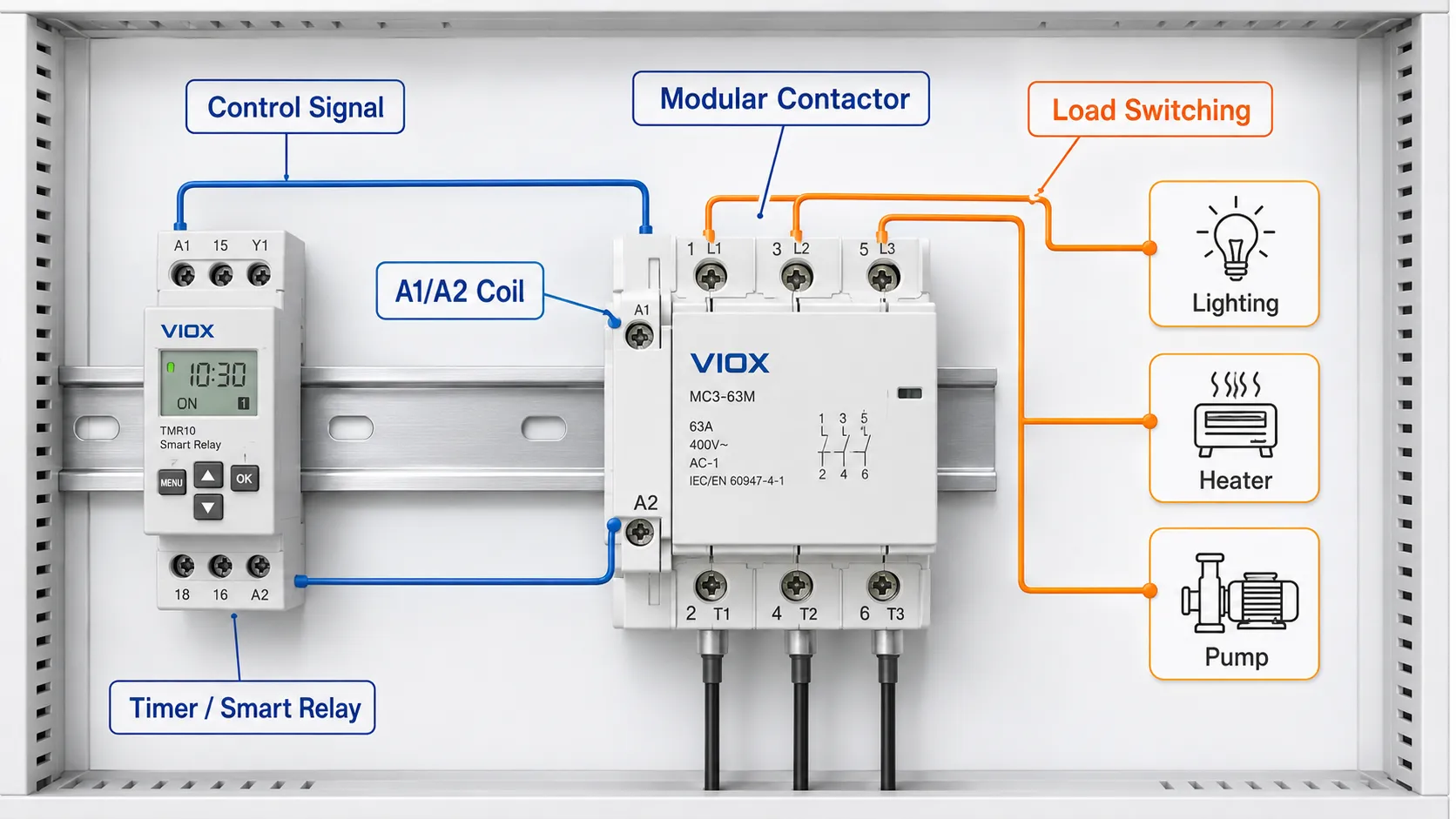
모듈형 접촉기 배선도 기초
항상 접촉기 본체에 인쇄된 배선도와 제조사의 데이터시트를 따르십시오. 단자 표시는 모델, 극수, 접점 구성에 따라 다릅니다.
일반적인 모듈형 접촉기 배선 구성은 다음과 같습니다:
| 단자 영역 | 일반적인 표시 | 기능 |
|---|---|---|
| 코일 단자 | A1 / A2 | 접촉기 코일용 제어 전압 공급 |
| 주 입력 단자 | 1, 3, 5 또는 L1, L2, L3 | 극수에 따른 전원 입력 측 |
| 주 출력 단자 | 2, 4, 6 또는 T1, T2, T3 | 부하 측 출력 |
| 보조 연락처 | 13/14, 21/22 등. | 상태 신호, 인터록 또는 제어 피드백(해당 시) |
단상 모듈형 접촉기 배선
단순 단상 부하의 경우, 2극 모듈형 접촉기를 사용하여 상(Line)과 중성선(Neutral)을 개폐하거나, 현지 배선 관례 및 프로젝트 설계에 따라 필요한 도체를 연결할 수 있습니다.
기본 제어 개념:
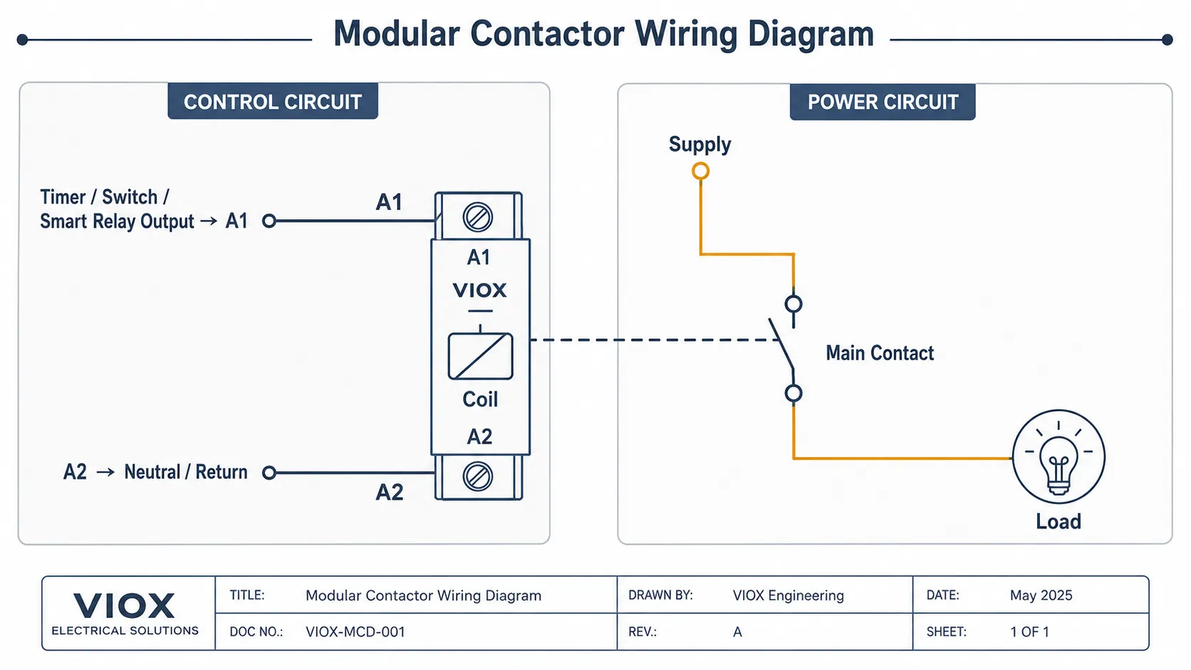
제어 회로:
제어 회로와 전력 회로는 별도로 이해해야 합니다. A1/A2 코일 단자는 일반적으로 부하에 직접 전원을 공급하지 않습니다. 이 단자들은 코일을 여자(energize)시키고, 주 접점이 부하를 개폐합니다.
3상 모듈형 접촉기 배선
3상 부하의 경우, 중성선 개폐 필요 여부에 따라 3극 또는 4극 모듈형 접촉기를 사용할 수 있습니다.
기본 개념:
L1 / L2 / L3 전원 공급 -> 전자접촉기 입력 단자
부하가 모터, 펌프, 팬, 압축기 또는 기타 유도성 부하인 경우, 해당 전자접촉기가 해당 부하 범주 및 기동 특성에 적합한 정격인지 확인하십시오. 설계에 필요한 과부하 및 단락 보호 기능이 포함되어 있지 않다면 모듈형 전자접촉기를 완전한 산업용 모터 기동기로 취급하지 마십시오.
3상 회로에서 모듈형 전자접촉기는 스위칭 요소일 뿐입니다. 설계 시 여전히 적절한 상단 단락 보호, 올바른 도체 규격 선정, 데이터시트에 따른 정확한 단자 조임, 그리고 필요한 경우 모터 과부하 보호 장치가 필요합니다. 올바르게 배선된 전자접촉기라도 사용 범주, 돌입 전류 또는 인클로저 내부의 열을 무시하면 조기에 고장날 수 있습니다.
모터 보호 협조에 관해서는 다음을 참조하십시오. 모터 전원용 접촉기, 과부하 계전기 및 차단기 선정 방법.
A1 및 A2 코일 단자 설명
많은 전자접촉기 및 릴레이에서, A1 그리고 A2 코일 또는 제어 전원 단자를 식별하십시오. 코일 전압은 모델에 따라 12V, 24V, 110V, 120V, 220V, 230V 또는 기타 값일 수 있습니다.
배선 전 확인 사항:
- AC 또는 DC 코일
- 정격 코일 전압
- AC인 경우 주파수
- DC인 경우 극성
- 허용 전압 범위
- 제어 장치 접점 정격
- 서지 억제 요구 사항
- 제품의 배선도
흔한 설치 실수로는 24V 코일에 230VAC 제어 회로를 사용하거나, AC 전용 코일에 DC 제어 전원을 사용하는 경우가 있습니다. 이러한 실수는 고장이나 오작동을 유발할 수 있습니다.
제어 회로에 타이머 릴레이를 사용하는 경우, 타이머 출력 접점은 모듈형 접촉기 코일 부하에 적합한 정격이어야 합니다. 타이밍 애플리케이션은 다음을 참조하십시오. 타이머 릴레이란 무엇입니까? 그리고 올바른 타이머 릴레이를 선택하는 방법.
AC-7a 대 AC-7b: 많은 구매자가 놓치는 정격
가정용 및 유사한 용도로 사용되는 모듈형 접촉기의 경우, AC-7a 그리고 AC-7b 중요한 활용 범주입니다.
| 활용 범주 | 일반적인 부하 유형 | 선택 시 고려해야 할 의미 |
|---|---|---|
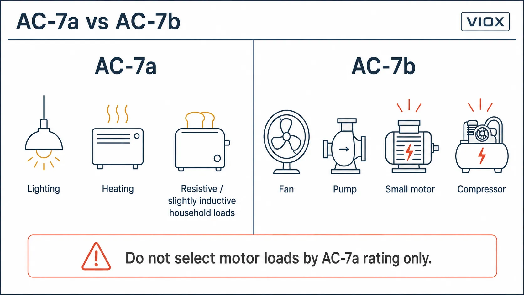
| AC-7a | 경부하 유도성 또는 저항성 가정용/유사 부하 | 난방, 조명 및 유사한 낮은 돌입 전류 부하에 공통적으로 사용 |
| AC-7b | 가정용/유사 용도의 모터 부하 | 팬, 펌프, 압축기 및 기동 전류가 있는 소형 모터에 적합 |
핵심은 간단합니다:
모듈형 접촉기가 모터나 유도성 부하를 개폐하는 경우, 인쇄된 암페어 정격만으로 선택하지 마십시오. AC-7b 정격 또는 제조사의 부하 표를 확인하십시오.
예를 들어, 접촉기는 모터 부하보다 저항성 또는 약간의 유도성 부하에 대해 더 높은 전류 정격을 가질 수 있습니다. 이는 제품의 품질이 낮다는 의미가 아닙니다. 접점의 사용 조건이 다르다는 것을 의미합니다. 모터 기동 전류, 역률, 접점 아크 및 개폐 빈도는 모두 전기적 수명에 영향을 미칩니다.
IEC 61095 대 IEC 60947-4-1
표준은 의도된 적용 환경을 명확히 하는 데 도움을 줍니다.
| 표준 맥락 | 일반적인 관련성 | 실제 의미 |
|---|---|---|
| IEC 61095 | 가정용 및 유사한 용도의 전자식 접촉기 | 배전반 및 유사한 설비에 사용되는 모듈형 접촉기와 일반적으로 관련됨 |
| IEC 60947-4-1 | 산업용 저압 개폐장치 및 제어장치용 접촉기 및 모터 기동기 | 산업용 AC 접촉기 및 모터 제어 애플리케이션과 일반적으로 관련됨 |
모든 모듈형 접촉기가 산업용 모터 접촉기라고 가정하지 마십시오. 또한 모든 산업용 접촉기가 배전반의 저소음 스위칭에 적합하다고 가정해서도 안 됩니다. 올바른 장치는 표준 맥락, 사용 범주, 부하 유형, 듀티 사이클 및 프로젝트 요구 사항에 따라 결정됩니다.
귀하의 애플리케이션이 산업용 모터 기동기인 경우, 표준 AC 접촉기 또는 완전한 모터 기동기 설계가 모듈형 접촉기보다 더 적합할 수 있습니다.
모듈형 접촉기(Modular Contactor)와 가정용 접촉기(Household Contactor)는 동일한 것인가?
두 용어는 밀접하게 관련되어 있으나, 항상 동일한 방식으로 사용되는 것은 아님.
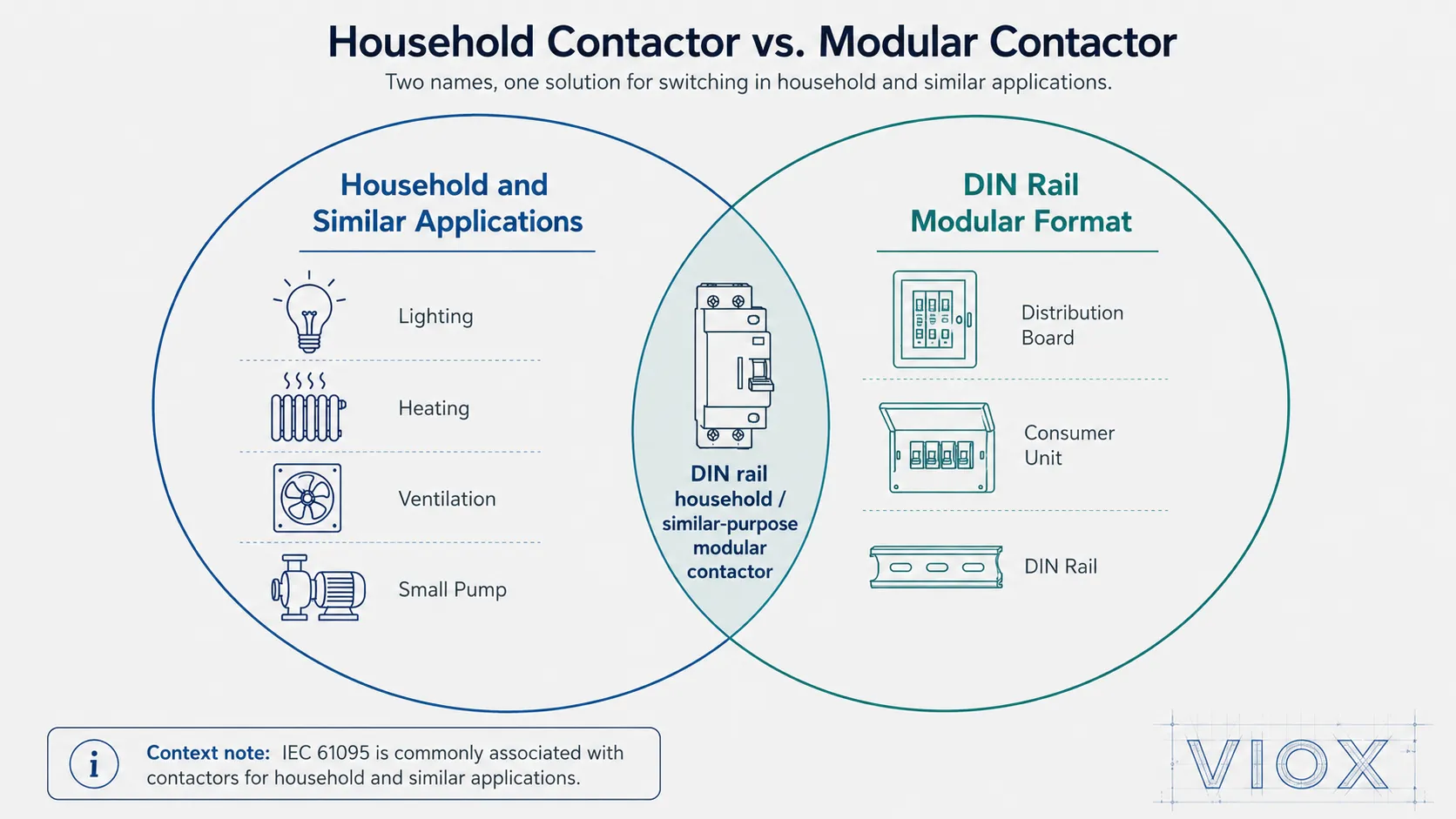
가정용 접촉기(Household contactor) 일반적으로 조명, 난방, 환기, 소형 펌프 또는 건물 서비스 회로와 같은 가정 및 유사 설비의 부하 개폐라는 애플리케이션 환경을 의미함. 이 용어는 IEC 61095 표준 방식의 사용과 밀접하게 연관됨.
모듈형 접촉기(Modular contactor) 일반적으로 제품의 형태를 의미함: 모듈형 배전반, 소비자용 분전반 및 소형 제어반에 맞게 설계된 소형 DIN 레일 장착형 접촉기.
실제로는 많은 제품이 두 가지 특성을 모두 가짐: 즉, 가정용 또는 유사 목적의 접촉기로 사용되는 모듈형 접촉기임. “가정용(household)”이라는 단어가 해당 장치가 가정에서만 사용된다는 것을 의미하지는 않음. 제품 정격, 표준 및 현장 프로젝트 요구 사항에 따라 유사한 주거용, 상업용 및 경량 건물 서비스 애플리케이션도 포함될 수 있음.
모듈형 접촉기(Modular contactor)는 배전반 및 빌딩 자동화 회로에서 소형 부하를 스위칭하기 위해 사용하는 DIN 레일 장착형 가정용 및 유사 목적의 접촉기입니다.
모듈형 접촉기는 어디에 사용됩니까?
모듈형 접촉기는 소형 DIN 레일 배전반에서 부하를 자동으로 스위칭해야 하는 애플리케이션에 일반적으로 사용됩니다.
일반적인 응용 분야는 다음과 같습니다.
- 상업용 건물의 조명 회로
- 온수기 및 난방 부하
- 환기 팬
- 소형 펌프
- 빌딩 설비 내 소형 모터
- HVAC 보조 회로
- 스마트 홈 부하 제어
- 빌딩 자동화 패널
- 타이머 제어 회로
- 전기차(EV) 충전기 보조 제어 회로
- 부하 차단 또는 예약 스위칭
정확한 적합성은 부하 전류, 돌입 전류, 사용 범주, 코일 전압, 스위칭 빈도 및 접촉기와 함께 사용되는 보호 장치에 따라 달라집니다.
스마트 제어 및 에너지 관리를 위한 모듈형 접촉기
모듈형 접촉기(Modular contactor)는 제어 신호에 따라 부하를 개폐하는 스위칭 요소로 자주 사용됩니다.
일반적인 제어 소스는 다음과 같습니다:
| 제어 소스 | 일반적인 사용 |
|---|---|
| 타이머 릴레이 | 조명, 난방, 환기, 펌프의 예약 운전 |
| 스마트 릴레이 또는 자동화 모듈 | 원격 또는 프로그래밍된 부하 제어 |
| 온도 조절 | 난방 또는 환기 제어 |
| 플로트 스위치 | 펌프 제어 |
| 에너지 관리 컨트롤러 | 부하 차단 또는 우선 부하 스위칭 |
| 전기차(EV) 충전기 컨트롤러 | 보조 스위칭 또는 부하 관리 회로 |
스마트 장치는 해당 용도로 정격이 지정되지 않은 경우, 일반적으로 고전력 부하를 직접 스위칭해서는 안 됩니다. 대신 모듈형 접촉기(Modular Contactor)의 코일을 스위칭하고, 모듈형 접촉기가 부하를 스위칭하도록 구성해야 합니다.
이 아키텍처는 제어 측을 단순하게 유지하며 접촉기가 정격 부하 내에서 부하 전류를 처리할 수 있도록 합니다.
모듈형 접촉기 선택 방법
모델을 선택하기 전에 이 체크리스트를 사용하십시오.
| 선택 항목 | 확인할 사항 | 왜 중요한가 |
|---|---|---|
| 정격 전류 | 실제 작동 조건에서의 부하 전류 | 과열 및 접점 과부하 방지 |
| 활용도 카테고리 | AC-7a, AC-7b 또는 기타 적용 가능한 범주 | 저항성, 유도성 또는 모터 부하에 접촉기 매칭 |
| 극 번호 | 1P, 2P, 3P, 4P | 회로 배선 및 절연 요구 사항 매칭 |
| 코일 전압 | AC/DC, 12V/24V/110V/230V 등. | 제어 회로와 일치해야 함 |
| 접점 구성 | 상시 개방(NO), 상시 폐쇄(NC), 혼합 접점 | 스위칭 로직 결정 |
| 부하 유형 | 조명, 난방, 모터, 펌프, 팬, 전기차(EV) 보조 회로 | 돌입 전류 및 접점 마모에 영향 |
| 스위칭 주파수 | 부하 스위칭 빈도 | 전기적 수명에 영향을 미침 |
| 소음 요구 사항 | 저소음 건축용 분전반 또는 산업용 제어반 | 주거 및 상업 환경에서 중요함 |
| 액세서리 | 보조 접점, 표시기, 수동 조작 장치, 스페이서 | 모니터링, 인터록 및 설치에 도움을 줌 |
| 표준 및 문서화 | IEC 61095, IEC 60947 관련 규격, 현장 프로젝트 요구 사항 | 승인 및 사양 준수를 위해 필요함 |
현장 사례: 조명용 접촉기가 모터 문제로 이어지는 경우
패널 검토 시 흔히 하는 실수는 조명이나 난방용으로 선정된 모듈형 접촉기를 소형 팬이나 펌프를 제어하는 데 사용하는 것입니다. 운전 전류는 허용 범위 내로 보일 수 있으나, 기동 전류와 유도성 부하 특성은 저항성 부하보다 접점에 훨씬 더 큰 부담을 줄 수 있습니다.
이것이 부품을 승인하기 전에 AC-7a 및 AC-7b 등급을 확인해야 하는 이유입니다. 모터 부하는 모터 유형, 공급 조건, 기계적 부하에 따라 기동 시 운전 전류의 수 배에 달하는 전류를 소비할 수 있습니다. 정확한 값은 일반적인 경험칙이 아닌 모터 데이터, 장비 제조사 또는 프로젝트 계산서를 통해 확인해야 합니다.
전문가 끝: 실제 패널 검토 시 소형 펌프나 팬의 운전 전류는 기동 전류보다 훨씬 낮은 경우가 많습니다. 일부 소형 모터는 모터 설계, 공급 전압, 부하 관성, 기동 방식에 따라 정격 운전 전류의 수 배를 소비할 수 있습니다. 이것이 AC-7b 등급이나 제조사의 모터 부하 표가 중요한 이유입니다. AC-7a는 저항성 또는 경미한 유도성 가정용 부하에는 적합하지만, 모터 부하 선정의 유일한 근거로 사용해서는 안 됩니다.
팬, 펌프, 압축기 또는 소형 모터의 경우 다음을 확인하십시오:
- AC-7b 등급 또는 제조사의 모터 부하 정격
- 스위칭 주파수
- 기동 시 코일 전압 안정성
- 상단 단락 보호
- 모터 요구 시 과부하 보호
- 데이터시트상의 단자 도체 규격 범위
- 제조사 단자 체결 토크 요구사항
- 외함 온도 및 환기
이러한 방식의 점검은 접촉기(contactor)가 암페어 기준으로 “충분히 큰지” 단순히 묻는 것보다 더 유용합니다.
극수: 1P, 2P, 3P 및 4P
극수는 접촉기가 스위칭하는 도체의 수를 결정합니다.
| 극 수 | 일반적인 사용 |
|---|---|
| 1P | 단순 제어 회로에서의 단일 도체 스위칭 |
| 2P | 두 개의 도체가 스위칭되는 단상 부하 |
| 3P | 중성선 스위칭이 없는 3상 부하 |
| 4P | 3상 및 중성선 스위칭 또는 다중 도체 제어 요구 사항 |
편의성만으로 극수를 선택하지 마십시오. 회로 설계, 현지 배선 규정, 중성선 스위칭 요구 사항 및 절연 전략을 따르십시오.
장착 옵션 및 모듈형 액세서리
모듈형 접촉기가 널리 사용되는 한 가지 이유는 설치 편의성 때문입니다. 일반적으로 DIN 레일 장착용으로 설계되어 MCB, RCBO, 타이머, 릴레이, 계측기 및 기타 모듈형 장치 옆에 설치할 수 있습니다.
유용한 액세서리 또는 설계 기능은 다음과 같습니다:
- 보조 접점 모듈
- 모델에 따른 수동 조작 또는 테스트 레버
- 표시창
- 방열용 스페이서
- 봉인 가능한 커버
- 저소음 코일 설계
- 지원되는 경우 호환 가능한 버스바 또는 배선 액세서리
- 명확한 단자 표시
패널 제작자에게 있어 액세서리 호환성은 배선 시간을 단축하고 유지보수를 용이하게 할 수 있습니다. 그러나 액세서리 가용성은 “모듈형'이라는 단어만으로 추측해서는 안 되며, 반드시 정확한 제품 시리즈를 확인해야 합니다.”
모듈형 접촉기(Modular Contactor) vs 릴레이(Relay) vs 타이머 릴레이(Timer Relay)
이 장치들은 서로 관련이 있지만 상호 교체하여 사용할 수 없습니다.
| 장치 | 주요 작업 | 일반적인 사용 |
|---|---|---|
| 모듈형 접촉기(Modular contactor) | 전자기 접점을 사용하여 부하 회로를 개폐합니다. | 조명, 난방, 팬, 펌프, 빌딩 자동화 부하 |
| 제어 릴레이(Control relay) | 저전력 제어 신호를 개폐합니다. | 인터록, 신호 전달, PLC 입력, 제어 로직 |
| 타이머 릴레이 | 시간 지연 후 접점 상태를 변경합니다. | 지연 시작/정지, 주기적 타이밍, 조명 또는 펌프 타이밍 제어. |
| 표준 AC 전자접촉기(Contactor). | 산업용 부하 및 모터를 스위칭합니다. | 모터 스타터, 기계 장치, 산업용 제어반. |
타이머 릴레이는 모듈형 전자접촉기의 코일을 제어할 수 있지만, 부하 전류가 타이머 릴레이 접점 정격을 초과하는 경우 일반적으로 전자접촉기를 대체해서는 안 됩니다.
일반적인 선택 실수
실수 1: 암페어 정격만 보고 선택하는 경우.
인쇄된 전류 정격만으로는 충분하지 않습니다. 사용 범주와 부하 유형을 확인하십시오. 모터 부하는 저항성 가열 부하와는 다르게 접점에 스트레스를 줄 수 있습니다.
실수 2: AC-7a와 AC-7b 규격 무시
부하가 팬, 펌프, 압축기 또는 모터인 경우 AC-7b 정격이 중요합니다. 모터 부하에 AC-7a 정격만 사용하면 수명이 단축되거나 접점 문제가 발생할 수 있습니다.
실수 3: 모듈형 접촉기를 완전한 모터 기동기로 사용
접촉기는 스위칭 장치입니다. 모터 회로에는 과부하 보호 및 단락 보호 기능도 필요합니다. 모듈형 접촉기는 그 자체로 이러한 기능을 자동으로 제공하지 않습니다.
실수 4: 잘못된 코일 전압 선택
제어 회로는 코일 전압과 일치해야 합니다. 배선 전에 AC/DC 유형, 전압 값 및 극성을 확인하십시오.
실수 5: 스마트 모듈로 부하를 직접 스위칭
스마트 릴레이나 컨트롤러는 제어 신호용으로는 적합할 수 있으나 부하를 직접 스위칭하는 데는 적합하지 않을 수 있습니다. 부하 전류나 돌입 전류가 컨트롤러 정격을 초과하는 경우, 이를 사용하여 접촉기 코일에 전원을 공급하십시오.
실수 6: 밀집된 DIN 레일 배전반의 발열 무시
배전반 내에 여러 모듈형 장치를 빽빽하게 설치하면 열이 발생할 수 있습니다. 간격, 환기, 정격 전류 및 제조업체의 설치 지침을 확인하십시오.
자주 묻는 질문
모듈형 접촉기(Modular Contactor)란 무엇입니까?
모듈형 접촉기는 제어 신호로부터 전기 부하를 전환하는 데 사용되는 소형 DIN 레일 접촉기입니다. 일반적으로 배전반, 분전반 및 빌딩 자동화 패널에 설치됩니다.
모듈형 접촉기와 일반 접촉기의 차이점은 무엇입니까?
모듈형 접촉기는 건물 및 배전반 애플리케이션을 위해 소형 모듈형 DIN 레일 형식으로 설계되었습니다. 일반 AC 접촉기는 주로 산업용 제어 패널, 기계 부하 및 더 무거운 모터 제어 작업을 위해 설계됩니다.
모듈형 접촉기는 어떻게 배선합니까?
일반적으로 A1 및 A2로 표시된 코일 단자는 제어 회로에 연결됩니다. 주 접점은 부하 회로를 전환합니다. 정확한 모델에 대한 인쇄된 배선도와 데이터시트를 항상 따르십시오.
모듈형 접촉기(Modular Contactor)에서 A1과 A2는 무엇입니까?
A1과 A2는 일반적으로 코일 단자입니다. A1/A2에 올바른 제어 전압을 인가하면 접촉기 코일이 여자되어 주 접점의 상태가 변경됩니다.
모듈형 접촉기에서 AC-7a란 무엇입니까?
AC-7a는 난방 및 특정 조명 애플리케이션과 같이 약간의 유도성 부하 또는 저항성 가정용 및 유사 부하와 일반적으로 관련된 사용 범주입니다.
모듈형 접촉기에서 AC-7b란 무엇입니까?
AC-7b는 가정용 및 유사 애플리케이션의 모터 부하를 위한 사용 범주입니다. 팬, 펌프, 압축기 또는 소형 모터를 스위칭할 때 중요합니다.
모듈형 접촉기로 모터를 제어할 수 있습니까?
네, 접촉기가 모터 부하에 대해 정격이 지정되어 있고 회로에 적절한 과부하 및 단락 보호 기능이 포함되어 있다면 가능합니다. AC-7b 정격, 기동 전류, 스위칭 빈도 및 제조업체의 지침을 확인하십시오.
타이머 릴레이로 모듈형 접촉기(modular contactor)를 제어할 수 있습니까?
네, 가능합니다. 타이머 릴레이의 출력 접점이 코일 부하에 적합한 정격이라면 모듈형 접촉기의 코일에 전원을 공급할 수 있습니다. 이후 모듈형 접촉기가 전력 부하를 스위칭합니다.
모듈형 접촉기는 스마트 접촉기와 동일합니까?
반드시 그렇지는 않습니다. 모듈형 접촉기는 모듈형 폼 팩터를 가진 기계식 스위칭 장치입니다. 타이머, 스마트 릴레이, 자동화 컨트롤러 또는 에너지 관리 장치에 의해 구동될 때 스마트 제어 시스템의 일부가 됩니다.
모듈형 접촉기에는 어떤 표준이 적용됩니까?
IEC 61095는 일반적으로 가정용 및 유사한 용도의 전자 기계식 접촉기와 관련이 있습니다. IEC 60947-4-1은 일반적으로 산업용 접촉기 및 모터 스타터와 관련이 있습니다. 적용 가능한 표준은 제품 및 프로젝트 요구 사항에 따라 다릅니다.
결론
모듈형 접촉기는 배전반 및 빌딩 자동화 회로를 위한 소형 DIN 레일 부하 스위칭 장치로 이해하는 것이 가장 좋습니다. 조명, 난방, 환기, 펌프, 소형 모터, 타이머 제어 회로 및 스마트 에너지 관리 애플리케이션에 유용합니다.
올바르게 선택하려면 먼저 부하 유형을 확인하십시오. 그런 다음 정격 전류, AC-7a 또는 AC-7b 부하 등급, 코일 전압, 극수, 접점 구성, 배선도, 액세서리 및 보호 협조를 확인하십시오. 부하가 모터나 산업용 기계인 경우, 모듈형 접촉기를 그 자체로 완전한 모터 스타터로 취급해서는 안 됩니다.
VIOX는 DIN 레일 배전, 빌딩 자동화, 타이머 제어 부하 및 OEM 패널 프로젝트를 위한 모듈형 접촉기 및 관련 제어 제품을 공급합니다. 다음에서 시작하십시오. 모듈 접촉기 제품 페이지, 또는 다음과 같은 관련 옵션을 비교하십시오. AC 접촉기 그리고 타이머 릴레이.
