On this page
A DC surge protective device (DC SPD) limits transient overvoltage on a direct-current power circuit. Correct selection begins with the function of the protected circuit, not simply its voltage: dedicated photovoltaic-generator DC applications fall under IEC 61643-31; eligible non-photovoltaic DC power applications fall under IEC 61643-41; AC power circuits use IEC 61643-11; telecommunications and signalling circuits use IEC 61643-21.
After identifying the correct product-standard scope, verify maximum continuous DC voltage, source and fault-current behavior, protection modes, surge duty, voltage protection level, grounding arrangement, disconnection, and backup protection. A solar SPD and a battery SPD are not automatically interchangeable because both labels show the same voltage.
Key Takeaways
- PV-generator DC: evaluate IEC 61643-31:2018, including the standard’s stated exclusion for SPDs associated with PV energy-storage systems.
- Non-PV DC power: evaluate IEC 61643-41:2025 with applicable IEC 61643-01 requirements, plus actual source and fault conditions.
- AC supply circuits: use the AC-specific IEC 61643-11:2025; do not cite it as the current blanket product standard for battery, EV, or industrial DC power.
- Data and signalling: use IEC 61643-21:2025 where applicable, including communication lines that also carry power.
- Select voltage rating against the highest credible continuous circuit voltage; for PV, account for open-circuit voltage at the lowest relevant cell temperature.
- Check prospective short-circuit current, source behavior, disconnector capability, backup protection, and the manufacturer’s stated protection modes before accepting any DC SPD.
Which IEC Standard Applies to Each Circuit?
| Protected circuit | Starting product-standard assessment | Why it belongs in this category | Important limitation |
|---|---|---|---|
| PV-generator DC string, combiner output, or PV-side inverter input | IEC 61643-31:2018 | The published scope specifically addresses the DC side of photovoltaic generators and inverters. | The standard excludes SPDs for PV systems with energy storage such as batteries or capacitor banks. |
| Battery-connected DC power, non-PV DC bus, or eligible industrial DC power | IEC 61643-41:2025 with applicable IEC 61643-01 requirements | Part 41 addresses DC low-voltage power circuits and equipment up to 1,500 V DC. | Source characteristics, temporary overvoltage, fault current, exact product scope, and equipment-specific rules require separate assessment. |
| EV charging AC input, inverter AC output, or AC distribution panel | IEC 61643-11:2025 with applicable IEC 61643-01 requirements | Part 11 addresses AC low-voltage power circuits and equipment. | An AC product-standard reference does not establish suitability for a DC power circuit. |
| Ethernet, PoE, RS485, instrumentation, or other eligible signalling interface | IEC 61643-21:2025 with IEC 61643-01:2024 | Part 21 addresses telecommunications and signalling networks, including lines that also provide power. | A communication line carrying DC power does not automatically become a Part 41 DC power circuit. |
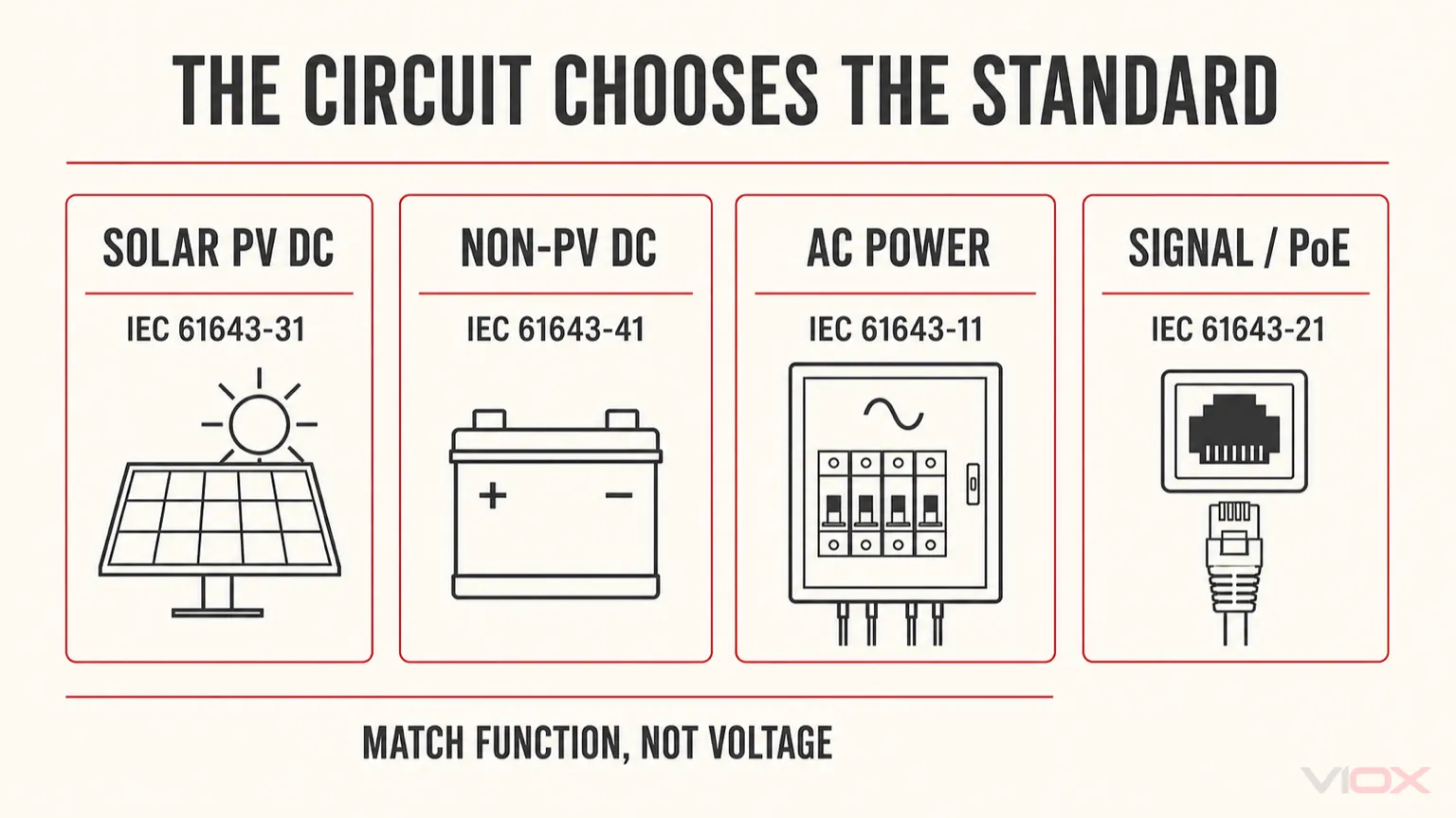
The standard number identifies an assessment framework; it does not establish that every model is suitable for every circuit inside that scope. Check the exact edition, product documentation, declared operating modes, project market, and actual installation conditions.
For the broader publication-by-publication crosswalk, see IEC 61643 SPD standards explained.
Why DC SPD Selection Differs From AC SPD Selection
DC circuits maintain a sustained polarity rather than following the regular alternating-voltage zero crossings of an AC system. That changes voltage stress, source behavior, fault interruption, disconnector design, and coordination.
The consequences depend on the source:
- A PV array has source characteristics governed by the modules, irradiance, temperature, and string configuration.
- A battery bank can present substantial available energy and prospective fault current.
- An EV charging converter can impose equipment-specific grounding, isolation, control, and fault conditions.
- An industrial DC supply can be grounded, floating, isolated, bipolar, current-limited, or backed by a battery or capacitor bank.
An AC-only SPD should not be installed on a DC circuit without explicit model-specific manufacturer approval for that DC application. Conversely, a PV-rated SPD should not be treated as automatically suitable for a battery bus, and a general DC SPD should not be assumed suitable for a PV-generator circuit.
DC SPD Ratings: Convert Operating Conditions Into Specifications
| Selection variable | Common declaration | What to establish | What not to assume |
|---|---|---|---|
| Continuous operating voltage | DC Uc, Ucpv, or market-specific MCOV | The maximum credible continuous voltage in each declared protection mode. | Nominal bus voltage equals worst-case operating voltage. |
| Protection level | Up or applicable market-specific declaration | The device and installed connection must protect the equipment’s relevant impulse-withstand level. | The datasheet Up alone includes all field wiring voltage drop. |
| Repeated surge duty | In, where applicable | The declared nominal discharge current and test basis fit the assessed exposure. | A larger advertised peak current automatically improves every installation. |
| Maximum surge duty | Imax, where applicable | The declared waveform, per-mode/per-pole basis, and intended duty are suitable. | Aggregate marketing kA values are directly comparable with per-mode declarations. |
| Lightning impulse duty | Iimp, where applicable | The design and risk assessment actually call for the declared lightning-current test duty. | Every outdoor system automatically needs the same Type 1 rating. |
| Short-circuit behavior | Applicable short-circuit withstand/current declaration, such as Isccr; SCCR where that framework applies | Available fault current, tested backup device, disconnector behavior, and manufacturer limits. | SCCR is the universal marking terminology for every IEC product. |
| Protection modes | DC+/DC−, DC+/PE, DC−/PE, or stated alternative | The protection arrangement matches source grounding, system topology, and protected conductors. | Every two- or three-module device has the same internal connection. |
IEC and North American terminology must remain in its own framework. UL 1449 market requirements, product listings, voltage-protection ratings, and installation categories should be checked when the project explicitly requires them; they are not automatically interchangeable with IEC declarations.
For a deeper parameter-by-parameter review, see how to read an SPD datasheet.
Solar PV DC: Start With Cold-Corrected Open-Circuit Voltage
PV modules can reach a higher open-circuit voltage when operating below their reference temperature. Selecting an SPD based only on nominal string voltage can therefore leave inadequate voltage margin.
Use the module manufacturer’s voltage-temperature coefficient and the lowest relevant design cell temperature. A simplified linear screening equation is:
Voc,cold ≈ Voc,STC × [1 + |βVoc| × (25°C − Tmin)]
String Voc,cold ≈ number of series modules × module Voc,cold
The coefficient must be entered as a fraction per degree Celsius. For example, a module with a 45 V open-circuit voltage at standard test conditions, a voltage coefficient magnitude of 0.0028/°C, and a design cell temperature of −10°C gives:
Module Voc,cold ≈ 45 × [1 + 0.0028 × 35]
Module Voc,cold ≈ 49.41 V
20-module string Voc,cold ≈ 988.2 V
This is an illustrative calculation, not a product recommendation. Final PV design must use the actual module datasheet, applicable temperature method, relevant local design conditions, inverter limits, system grounding, tolerances, and manufacturer requirements. Select a PV SPD whose declared Ucpv and protection modes remain suitable for the complete worst-case circuit.
Where PV DC Protection Is Evaluated
Typical assessment locations include the PV combiner, the PV-side inverter input, and other exposed transitions identified by the lightning-risk assessment and installation design.
Long or externally routed conductors can justify evaluating protection at more than one location. Do not present a fixed cable-length threshold or universal Type selection unless the applicable standard, installation rule, project specification, or manufacturer’s instructions support it.
Use the solar SPD selection guide for the dedicated photovoltaic application.
Battery Energy Storage: Fault Current Changes the Decision
A battery energy storage system (BESS) can contain several different electrical circuits, each requiring its own protection assessment:
- Battery-connected DC circuits and eligible non-PV DC buses: assess IEC 61643-41 and applicable IEC 61643-01 requirements.
- Dedicated PV-generator DC conductors, if separately present: assess IEC 61643-31 within its actual published scope.
- Power-conversion-system AC output and grid connection: assess IEC 61643-11.
- Battery-management, Ethernet, monitoring, and signalling interfaces: assess IEC 61643-21 where applicable.
The critical distinction is not that one system contains solar equipment. It is whether the specific protected circuit is PV-generator DC, battery/non-PV DC power, AC power, or signalling.
IEC 61643-41 notes that its test assumptions are based on a DC power source with a linear voltage-current characteristic and calls for careful consideration when source characteristics differ, particularly regarding prospective short-circuit current and temporary overvoltage. Battery systems therefore require model-specific evidence of suitability, coordinated disconnection, and backup protection—not merely a voltage match.
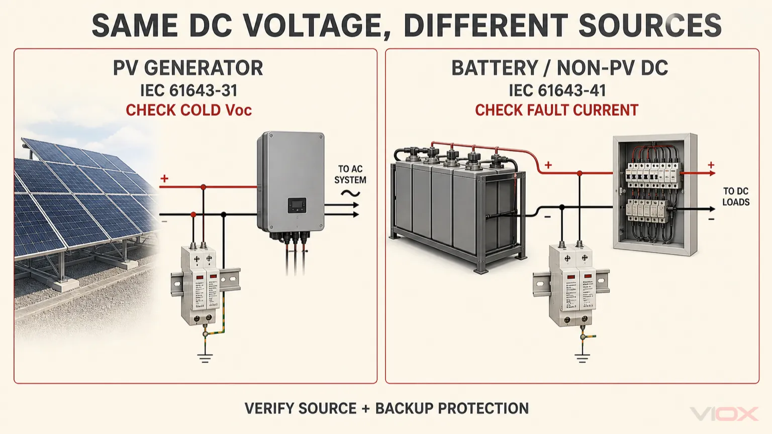
For the complete mixed-circuit architecture, see BESS surge protection across DC, AC, and signal circuits.
EV Charging: Classify the Circuit, Not the Charging Station
An EV charger can include an AC supply, internal DC conversion stage, DC output, control power, metering, networking, and communication interfaces. One SPD declaration does not cover every section.
| Charger section | Starting SPD assessment | Additional checks |
|---|---|---|
| AC input or upstream AC distribution | IEC 61643-11 and relevant market requirements. | System voltage, earthing arrangement, location, surge duty, and external protection. |
| Eligible non-PV DC power section | IEC 61643-41 and applicable IEC 61643-01 requirements. | Charger architecture, voltage range, source behavior, isolation, fault current, and manufacturer approval. |
| Control power bus | Part 41 when it is genuinely a DC power circuit within scope. | Actual rail voltage, grounding, continuity requirements, and available fault current. |
| Ethernet, communications, or PoE | IEC 61643-21 when the interface falls within its signalling scope. | Connector, bandwidth, shielding, power delivery, insertion loss, and bonding. |
The charger manufacturer’s equipment architecture and applicable charging-equipment standards can impose additional requirements. Do not prescribe an internal installation point or assert that every DC output needs the same SPD without the manufacturer’s design documentation and the project risk assessment.
Industrial and Telecom DC: Nominal Voltage Is Only the Beginning
Industrial facilities may use low-voltage control supplies, telecom DC distribution, battery-backed control power, or higher-voltage DC buses. The same nameplate rail can have very different grounding and fault characteristics.
Before choosing an industrial DC SPD, record:
- Normal and maximum continuous voltage, including charger float or boost conditions where applicable.
- Positive-grounded, negative-grounded, floating, isolated, or bipolar source arrangement.
- Which conductors and protection modes require coordination.
- Source fault-current capability, storage contribution, and fault-clearing arrangement.
- Impulse withstand of connected equipment and the installed connection path.
- Environmental conditions, service access, remote signalling, and continuity requirements.
- Whether the protected conductors carry DC power or a communication signal.
A telecom power plant may involve a DC power bus assessed under Part 41 and a separate Ethernet or signalling connection assessed under Part 21. The presence of DC voltage does not collapse those circuit functions into one standard.
Type 1, Type 2, and Combined DC Protection
The relevant surge test duty and SPD classification must match the product standard, manufacturer declaration, installation position, lightning-risk assessment, and system design.
Where the applicable framework and product documentation use these designations:
- Type 1 or combined Type 1+2 capability may be considered when the actual design requires a declared lightning-current duty.
- Type 2 capability may be appropriate for distribution-level induced and switching surges when the assessed exposure and manufacturer guidance support that choice.
- Multiple stages require verified coordination; they cannot be assumed compatible merely because their printed type numbers differ.
The existence of an external lightning protection system does not, by itself, establish a universal SPD configuration for every conductor, installation position, or earthing arrangement. Use Type 1 vs. Type 2 vs. Type 3 SPD selection for the dedicated classification question.
Installation: Bonding, Lead Length, and Backup Protection
Correct device ratings do not compensate for poor installation. The SPD must connect according to its exact diagram and the grounding architecture of the protected DC circuit.
Keep the complete connection between the protected conductors, any specified backup device, SPD terminals, and approved protective bonding point as short and direct as practical. Fast-rising surge current can create additional conductor voltage drop, increasing the protection level seen by the equipment.
Use the installation’s approved, coordinated bonding arrangement. Do not connect an SPD to an isolated ground rod, invent an additional neutral-ground bond, or change the system grounding reference without an engineered and code-compliant design.
Check the following before commissioning:
- The positive, negative, and PE connections match the manufacturer diagram and actual system topology.
- The selected DC Uc or Ucpv covers worst-case continuous voltage in the relevant mode.
- The prospective fault current does not exceed the device’s applicable declared short-circuit capability with its specified protective arrangement.
- External fuses or breakers are DC-rated where required and match the SPD manufacturer’s tested coordination conditions.
- Internal disconnectors and remote indication behave as specified for the actual source and fault environment.
- The installed voltage protection level and placement are compatible with the equipment being protected.
- Adjacent AC and communications circuits receive protection under their own appropriate product framework.
For full phase, neutral, PE, protective-device, and routing guidance, use the SPD wiring guide.
A Practical DC SPD Procurement Specification
Ask the supplier to identify the exact device against the following fields:
| Procurement field | Required information |
|---|---|
| Protected circuit | PV-generator DC, battery/non-PV DC power, industrial DC rail, or another defined circuit. |
| Standard and edition | Exact applicable IEC product part and edition, relevant Part 01 relationship, and required regional approval. |
| Maximum operating voltage | Worst-case continuous DC voltage and declared Ucpv, DC Uc, or applicable MCOV. |
| Grounding and protection modes | Grounded/floating/bipolar arrangement and actual DC+/DC−/PE mode declarations. |
| Surge and lightning duty | Declared In, Imax, Iimp where applicable, associated waveforms, and per-mode basis. |
| Equipment protection level | Declared Up and the installed connection assumptions relevant to equipment withstand. |
| Source and fault current | Actual source characteristics, available short-circuit current, and applicable declared short-circuit withstand/current information. |
| Backup protection | Required external device type, DC voltage rating, coordination conditions, and maximum manufacturer-permitted protective rating. |
| Monitoring and maintenance | Status indication, replaceable modules, optional remote contact, service access, and replacement instructions. |
| Evidence | Exact model datasheet, wiring diagram, relevant test report or certificate where required, and market-specific documentation. |
A useful RFQ does not say only “1500 V DC SPD, 40 kA.” It identifies the circuit, source, standard, grounding arrangement, voltage, protection modes, surge duty, fault-current conditions, and required product evidence.
Review the VIOX surge protection device range only after those application requirements are defined.
Primary Technical References
- IEC 61643-31:2018: SPDs for the DC side of photovoltaic installations.
- IEC 61643-41:2025: SPDs connected to DC low-voltage power systems.
- IEC 61643-11:2025: SPDs connected to AC low-voltage power systems.
- IEC 61643-21:2025: SPDs connected to telecommunications and signalling networks.
- IEC 61643-01:2024: Common requirements and test methods.
The applicable national adoption, manufacturer instructions, equipment-specific requirements, market rules, and actual protected-circuit conditions must be verified for every installation.