On this page
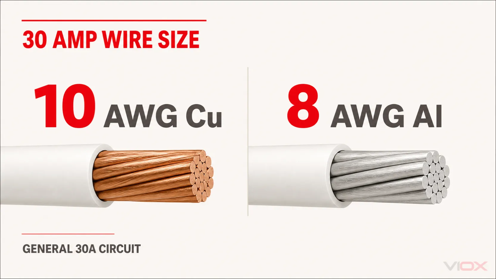
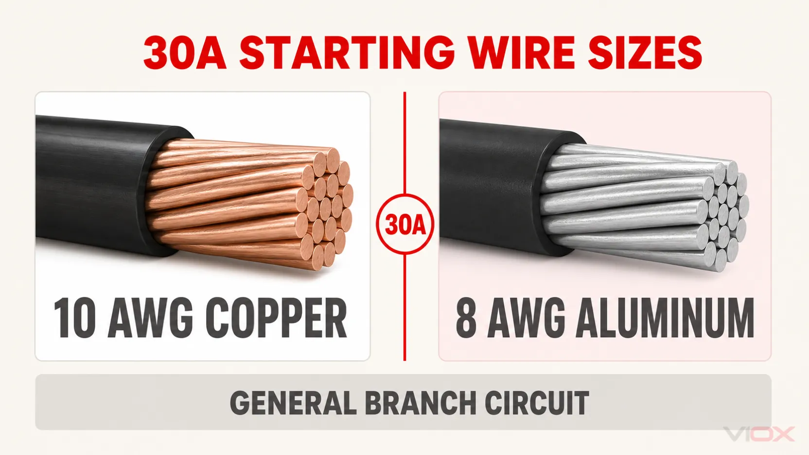
For most ordinary 30 amp circuits, use 10 AWG copper wire or 8 AWG aluminum wire. A standard 30A circuit normally supports no more than 24A of continuous load, because 24A × 125% = 30A.
That is the correct first-screen answer, not a universal installation prescription. The final 30 amp wire size still depends on the load calculation, conductor material, wiring method, terminal temperature ratings, ambient temperature, the number of current-carrying conductors, voltage drop, and any equipment-specific instructions.
Safety note: Branch-circuit design and panel work are code-dependent and can expose workers to lethal voltage and arc-flash hazards. Use the code adopted by the local authority having jurisdiction (AHJ), the equipment instructions, and a qualified electrician or electrical engineer for the final design and installation.
Code edition note: NFPA publishes the 2026 National Electrical Code (NEC), NFPA 70 as the current edition, but jurisdictions adopt different editions on different schedules. The 2026 edition also reorganized parts of the code. Where this article identifies a 2023 NEC section or table, treat the number as edition-specific and verify the equivalent rule in the edition enforced for the project.
30 Amp Wire Size at a Glance
| Proposed conductor or condition | Normal 30A decision | Why |
|---|---|---|
| 10 AWG copper NM-B | Yes, for a typical dry-location 30A circuit before any required correction or adjustment | NM-B ampacity is limited to the 60°C value; #10 copper is 30A at 60°C |
| 10 AWG copper THHN/THWN-2 in raceway | Yes, subject to terminals and installed conditions | Table ampacity may be higher, but the ordinary small-conductor overcurrent limit remains 30A |
| 12 AWG copper THHN/THWN-2 | No for an ordinary general-purpose 30A circuit | The 90°C table value does not override the normal small-conductor protection limit |
| 10 AWG aluminum or copper-clad aluminum | No for an ordinary 30A circuit | The 2023 NEC small-conductor rule normally limits it to 25A |
| 8 AWG aluminum XHHW-2 or THHN/THWN-2 | Common aluminum starting size, if both ends accept aluminum | Manufacturer data shows at least 30A ampacity under the relevant temperature conditions; terminals and product listing still control |
| HVAC equipment with MCA/MOCP markings | Use the nameplate calculation | Special equipment rules can permit a conductor-to-breaker relationship that a general lookup table would reject |
This table selects a starting conductor size. It does not by itself specify cable type, raceway, wet-location suitability, breaker compatibility, conductor count, grounding, or the load equipment’s connection requirements.
Key Takeaways
- 10 AWG copper is the normal answer for a general 30A branch circuit.
- 8 AWG aluminum is the normal aluminum starting size. Ten AWG aluminum is generally limited to 25A for ordinary branch-circuit protection.
- A normal 30A circuit supports up to 24A of continuous load. A load that draws 30A continuously requires at least 37.5A of circuit capacity before other factors are applied.
- The 35A or 40A table ampacity shown for some 10 AWG copper insulation does not normally authorize a 35A or 40A breaker.
- NM-B, THHN/THWN-2, and XHHW-2 are not interchangeable labels. Their permitted locations and usable ampacity conditions differ.
- There is no universal “100 ft maximum.” The same conductor and load have twice the voltage-drop percentage at 120V that they have at 240V.
- HVAC, motor, welder, and other special loads may follow equipment-specific rules. Read the nameplate and installation instructions before applying the general answer.
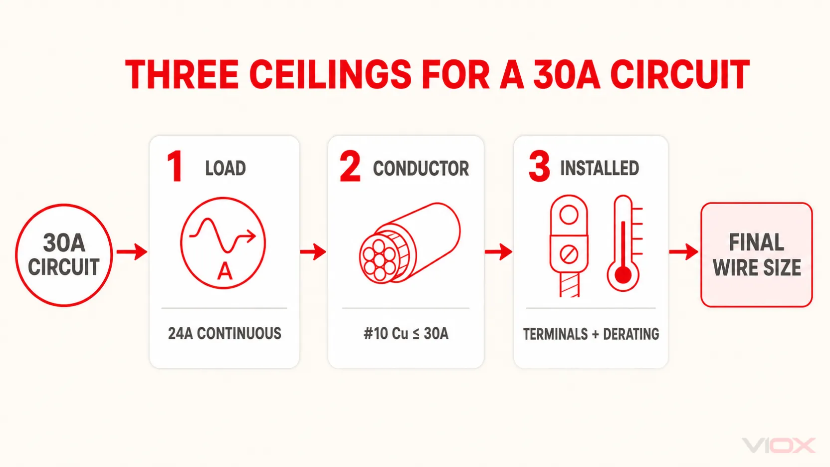
The Three Ceilings That Control 30 Amp Wire Size
A useful 30A conductor specification must pass three independent ceilings. Passing only one is not enough.
| Ceiling | Question to answer | 30A pass condition |
|---|---|---|
| 1. Load ceiling | What ampacity does the calculated load require? | Non-continuous load plus 125% of continuous load, or the applicable equipment calculation, does not exceed circuit capacity |
| 2. Conductor ceiling | What ampacity and overcurrent protection does this conductor actually permit? | The conductor passes its ampacity table, wiring-method rule, and small-conductor protection limit |
| 3. Installed ceiling | Do terminals and field conditions reduce the usable result? | Both ends accept the material/size/temperature basis, and adjusted ampacity remains adequate |
VIOX’s broader wire gauge and circuit breaker sizing chart shows the surrounding ampere ratings. This article goes deeper on the exact boundary that makes 10 AWG copper valid—or invalid—for a 30A circuit.
Ceiling 1: Calculate the Load Before Selecting the Wire
For a typical branch circuit containing continuous and non-continuous loads, the general sizing relationship is:
Required circuit ampacity = non-continuous load + 125% of continuous loadA continuous load is generally one expected to operate at maximum current for three hours or more. For an ordinary 30A circuit:
30A ÷ 1.25 = 24A maximum continuous loadThe practical power limits at that continuous current are:
120V × 24A = 2,880W240V × 24A = 5,760W
Voltage does not change the conductor’s basic ampacity, but it changes the available power and the percentage impact of voltage drop.
If a load itself draws 30A continuously:
30A × 1.25 = 37.5A required capacityThat load does not belong on an ordinary 30A circuit. It normally leads to a 40A-or-larger circuit design, with the conductor, overcurrent device, terminals, and equipment configuration recalculated together. Do not keep 10 AWG wire and simply increase the breaker. The VIOX guide to circuit-breaker load calculation explains the upstream sizing process.
Do Not Apply 125% Twice
Some equipment provides a required branch-circuit rating, Minimum Circuit Ampacity (MCA), or another value that already incorporates an equipment-specific calculation. Follow the nameplate, installation instructions, and applicable code method. Adding another 125% without checking the basis can oversize the circuit and still fail to follow the equipment rule.
Ceiling 2: Understand Why 10 AWG Copper Stops at 30A
The ampacity table and the maximum permitted breaker are related but not identical.
Under the 2023 NEC Table 310.16 reference conditions, 10 AWG copper is listed at:
| Temperature column | 10 AWG copper table ampacity |
|---|---|
| 60°C | 30A |
| 75°C | 35A |
| 90°C | 40A |
It is tempting to read the 75°C or 90°C value and conclude that 10 AWG THHN can use a 35A or 40A breaker. For ordinary circuits, that conclusion is wrong. 2023 NEC 240.4(D) generally limits 10 AWG copper to 30A overcurrent protection, after any required correction or adjustment factors are applied, unless a specific permission or equipment rule applies.
Southwire’s copper THHN/THWN-2 data makes this distinction explicit: its table ampacities are based on 2023 NEC Table 310.16, while its note separately identifies the 30A overcurrent-protection limit for 10 AWG copper.
The 90°C insulation rating still has value. It may be used as the starting ampacity for required correction or adjustment calculations when the applicable rules permit. It does not automatically upgrade the breaker, the equipment terminal, or the final usable ampacity.
The 10 AWG Copper Pass/Fail Check
| Proposed use | Pass or fail for ordinary 30A design? | Technical reason |
|---|---|---|
| 10 AWG copper NM-B, dry location, no derating below 30A | Pass | The 60°C ceiling is 30A and matches the breaker |
| 10 AWG copper THHN/THWN-2, permitted raceway, qualifying terminals | Pass | Table ampacity is adequate and the breaker remains within the 30A small-conductor limit |
| 10 AWG copper THHN on a 40A breaker because the insulation is 90°C | Fail | The 90°C table value does not erase the ordinary 30A protection limit |
| 10 AWG copper with correction/adjustment result below 30A | Fail | Installed allowable ampacity is insufficient |
| 10 AWG copper on HVAC equipment where nameplate MCA is satisfied and MOCP permits 30A | Equipment-specific | Apply the HVAC rules and nameplate, not the general-purpose shortcut |
This distinction is especially important when evaluating an existing installation. A 30A breaker and 10 AWG copper may be a valid general pairing, but the pairing alone does not prove the circuit passes the load calculation or installed-condition checks.
NM-B vs THHN/THWN-2 for a 30 Amp Circuit
Wire gauge is only one part of the specification. The wiring method determines where the conductor can be installed and which ampacity limitations apply.
10 AWG Copper NM-B
Type NM-B cable is widely used for residential branch circuits in dry locations. Southwire states that its copper NM-B cable is limited to the 60°C conductor ampacity, even though the individual conductor insulation inside the cable is rated 90°C.
For 10 AWG copper, that final 60°C ampacity is 30A. This makes 10 AWG copper NM-B a direct match for a normal 30A circuit, but it has no remaining ampacity above 30A after the wiring-method ceiling. If high ambient temperature or conductor grouping reduces the allowable ampacity below 30A, the design needs a larger conductor or a different installation arrangement.
NM-B is for dry locations. It is not made into a wet-location conductor by pulling it through outdoor or underground conduit. Also, the individual insulated conductors removed from an NM-B jacket are not separately listed as THHN/THWN-2.
10 AWG Copper THHN/THWN-2
Individual THHN/THWN-2 copper conductors are commonly installed in an approved raceway. Southwire identifies its THHN/THWN-2 product for dry and wet locations under the applicable temperature conditions and lists the higher 75°C and 90°C ampacities.
Those higher values provide useful derating headroom, but three limits remain:
- the ordinary 30A overcurrent limit for 10 AWG copper;
- the temperature rating of the breaker and load terminals; and
- the corrected and adjusted ampacity under the actual installation conditions.
Therefore, the technically correct statement is not “10 AWG THHN is a 40 amp wire.” It is: 10 AWG copper THHN/THWN-2 can have a 40A 90°C table ampacity while still being normally protected at no more than 30A in a general branch circuit.
Why 8 AWG Is the Normal Aluminum Wire Size for 30 Amps
Ten AWG aluminum is not the aluminum equivalent of 10 AWG copper. Under the 2023 small-conductor protection rule, 10 AWG aluminum and copper-clad aluminum are generally limited to 25A, so they are not the standard choice for a 30A breaker.
Eight AWG aluminum is the normal starting size. The following values show the relevant 8 AWG aluminum boundary:
| Aluminum conductor example | 60°C | 75°C | 90°C | 30A implication |
|---|---|---|---|---|
| 2023 NEC Table 310.16, 8 AWG aluminum/copper-clad aluminum | 30A | 40A | 45A | The 60°C value directly meets 30A before installed-condition checks |
| Southwire 8 AWG aluminum XHHW-2 | — | 40A | 45A | Manufacturer data confirms the 75°C/90°C values for this conductor family |
Ampacity is only the first check. Verify at both ends:
- the terminal is identified for aluminum, commonly with an AL or CU/AL marking;
- the terminal accepts 8 AWG conductors;
- the permitted temperature basis matches the calculation;
- the connector and preparation method follow the product instructions; and
- the selected aluminum conductor type is listed for the location and wiring method.
Do not assume that a receptacle or appliance terminal accepts aluminum just because the breaker terminal does. If the load equipment is copper-only, the design may require a listed transition method or a different conductor choice.
Ceiling 3: Verify Terminals and Installed Conditions
The usable ampacity is controlled by the most restrictive applicable part of the complete circuit—not by the highest number printed on the wire insulation.
Terminal Temperature and Conductor Compatibility
Before choosing an ampacity column, verify:
- breaker terminal temperature rating;
- load, disconnect, receptacle, or equipment terminal temperature rating;
- permitted conductor material: copper, aluminum, or both;
- accepted conductor size range; and
- any conductor requirement in the equipment installation instructions.
A larger wire is not automatically installable. If voltage drop or derating leads to an upsized conductor, confirm that it physically fits and is permitted at every termination, or use a listed transition solution designed for the application.
Ambient Temperature and Current-Carrying Conductors
Ampacity tables assume stated reference conditions. High ambient temperature and multiple current-carrying conductors grouped in a raceway or cable can reduce allowable ampacity.
For THHN/THWN-2, the 90°C value may provide the starting point for correction or adjustment when permitted, but the final result must still respect the 30A small-conductor limit, terminal ratings, and other installation ceilings. For 10 AWG copper NM-B, the final allowable ampacity cannot exceed its 30A 60°C ceiling.
The correct sequence is:
- identify the wiring method and insulation rating;
- apply required temperature and conductor-count factors;
- compare the result with the terminal and wiring-method limits; and
- confirm the final allowable ampacity is at least the calculated load requirement.
Voltage Drop: Why 10 AWG Is Good for 100 Feet Is Not a Rule
Voltage drop is a performance calculation, not a substitute for ampacity. A distance recommendation is meaningless without the voltage, current, one-way route length, conductor resistance, and acceptable performance target.
Southwire publishes an AC resistance of approximately 1.253 ohms per 1,000 ft at 75°C for its 10 AWG copper building wire. Consider a 24A continuous load located 100 ft one way from the panel.
Using a simplified single-phase resistance calculation:
Voltage drop = 2 × one-way length × current × resistance per footVD = 2 × 100 ft × 24A × 1.253 Ω/1,000 ft = 6.01VThe same 6.01V loss produces very different percentages:
| Circuit voltage | Calculated drop | Percentage drop |
|---|---|---|
| 120V | 6.01V | 5.01% |
| 240V | 6.01V | 2.51% |
At 150 ft one way, the same 10 AWG copper and 24A assumptions produce about 9.02V of drop: approximately 7.52% at 120V or 3.76% at 240V.
Upsizing to 8 AWG copper, for which Southwire publishes approximately 0.786 ohm per 1,000 ft at 75°C, reduces the 150 ft example to about 5.66V: approximately 4.72% at 120V or 2.36% at 240V.
These are transparent engineering examples, not universal distance limits. Actual results vary with load current, conductor temperature, power factor, circuit geometry, connection resistance, and equipment requirements. The key lesson is that a 100 ft rule can appear acceptable at 240V and perform poorly at 120V under the same current and conductor assumptions.
Equipment Boundaries That Can Change the General Answer
24A EV Charger on a 30A Circuit
Electric vehicle supply equipment (EVSE) is a useful continuous-load example. ChargePoint identifies a 24A charging setting with a 30A circuit breaker for its Home Flex product, confirming the 24A × 125% = 30A relationship. Its 30A configuration is hardwired, which also demonstrates why a current rating alone does not determine the connection method.
Use the actual EVSE installation instructions for conductor material, terminal range, breaker configuration, grounding, and commissioning. Do not assume every charger accepts the same wiring or settings.
Dryer, Water Heater, or Other Fixed Appliance
A 30A appliance circuit often uses 10 AWG copper, but the conductor count comes from the appliance—not the breaker number.
- A straight 240V load may require two ungrounded conductors plus an equipment grounding conductor.
- A 120/240V appliance may also require a neutral.
- The installation instructions may specify a dedicated circuit, conductor material, connection method, or minimum circuit rating.
This is why “10/2 or 10/3?” cannot be answered from 30 amps alone. Check the wiring diagram and nameplate before ordering cable.
HVAC Equipment with MCA and MOCP
Air-conditioning and refrigeration equipment can show a Minimum Circuit Ampacity (MCA) that permits a conductor smaller than a generic breaker chart suggests while the Maximum Overcurrent Protection (MOCP) permits a 30A breaker. The overcurrent device may be sized to accommodate compressor starting current while the conductor follows the equipment-specific ampacity calculation.
For HVAC equipment, size the conductor from the nameplate MCA and applicable equipment rules, and keep the breaker at or below the marked MOCP. A 30A breaker over 12 AWG copper is not a general permission—it can be valid only when the specific equipment calculation and installation satisfy the applicable rules.
Motors, welders, and certain other loads also have special sizing provisions. Do not turn an equipment-specific exception into a general wire-size shortcut.
Ground Wire, Neutral, and Conductor Count
For a 30A overcurrent device, the common 2023 NEC Table 250.122 starting point for a wire-type equipment grounding conductor is 10 AWG copper or 8 AWG aluminum/copper-clad aluminum. Other conditions can change the grounding design, and the reorganized 2026 edition uses different numbering, so verify the adopted code.
The neutral is determined by how the equipment uses voltage, not by breaker amperage:
- a 120V circuit normally requires one ungrounded conductor, a neutral, and equipment grounding;
- a straight 240V circuit may not require a neutral;
- a 120/240V circuit normally includes two ungrounded conductors, a neutral, and equipment grounding.
Whether the neutral counts as a current-carrying conductor for adjustment depends on how it carries load current. Confirm the actual circuit arrangement before applying conductor-count factors.
30 Amp Wire Size Project Worksheet
Complete every row before reducing the design to one AWG number:
| Required input | Project value | Decision produced |
|---|---|---|
| Equipment voltage and phase | ___ | Pole count and conductor arrangement |
| Non-continuous load | ___ A | Base calculated load |
| Continuous load | ___ A | Include at 125% where applicable |
| Equipment MCA/MOCP or specified branch-circuit rating | ___ | Confirms whether special equipment rules control |
| Copper or aluminum | ___ | Selects ampacity values and terminal material requirements |
| NM-B, THHN/THWN-2, XHHW-2, or other wiring method | ___ | Establishes location and ampacity limitations |
| Breaker terminal | ___ °C; CU/AL; ___ AWG | Sets one end’s usable material, column, and fit |
| Load terminal | ___ °C; CU/AL; ___ AWG | Sets the other end’s usable material, column, and fit |
| Ambient temperature | ___ | Correction-factor check |
| Current-carrying conductors | ___ | Adjustment-factor check |
| One-way route length | ___ ft | Voltage-drop calculation |
| Neutral and grounding requirements | ___ | Final conductor count and grounding specification |
If one of these inputs is unknown, the project is not ready for a final conductor specification.
Final Selection Rule
Use 10 AWG copper or 8 AWG aluminum as the normal starting wire size for a 30 amp breaker in a US NEC-style installation.
Then apply the three ceilings:
- Load: confirm the calculated load fits, including the 24A continuous-load limit for an ordinary 30A circuit.
- Conductor: confirm the wiring method, ampacity, and small-conductor protection rules permit the proposed pairing.
- Installation: verify terminal ratings, copper/aluminum compatibility, ambient temperature, conductor count, voltage drop, and equipment instructions.
Do not use a larger breaker to solve a load problem without recalculating and verifying the conductor and equipment. If the proposed change is from 20A to 30A, use the VIOX guide to changing a 20 amp breaker to a 30 amp breaker before treating it as a component swap.
For adjacent circuit ratings, compare the dedicated VIOX guides to 50 amp wire size and 60 amp breaker wire size. Once the electrical specification is established, engineers and panel builders can review the VIOX miniature circuit breaker family for application-appropriate product evaluation.
FAQ
Can 12 gauge wire be used on a 30 amp breaker?
Not for an ordinary general-purpose 30A branch circuit. The small-conductor protection rules normally limit 12 AWG copper to 20A, even when a 90°C insulation table shows a higher ampacity. A properly engineered motor, HVAC, welder, or other special-equipment circuit may follow different rules; that exception is specific to the equipment and calculation.
Is 10 gauge wire always enough for 30 amps?
No. Ten AWG copper is the normal starting size, but it can fail if the calculated load exceeds circuit capacity, correction or adjustment reduces allowable ampacity below the requirement, voltage drop is unacceptable, or the equipment instructions require a different conductor. Ten AWG aluminum is not the general 30A answer.
Can 10 AWG THHN carry 35 or 40 amps?
Its ampacity table may show 35A at 75°C and 40A at 90°C, but ordinary overcurrent protection for 10 AWG copper is generally limited to 30A. The higher insulation value can support permitted derating calculations; it does not automatically authorize a larger breaker.
What size aluminum wire is needed for a 30 amp breaker?
Use 8 AWG aluminum as the normal starting size, then verify the conductor type, terminal temperature ratings, aluminum compatibility, wire range, correction/adjustment factors, and equipment instructions at both ends. Ten AWG aluminum is generally limited to 25A for an ordinary circuit.
Is 10/2 or 10/3 needed for a 30 amp circuit?
It depends on the load. A straight 240V load may not need a neutral, while a 120/240V appliance normally does. In common cable naming, the equipment grounding conductor is not included in the “2” or “3” count. Follow the equipment wiring diagram rather than selecting cable from amperage alone.
How many watts can a 30 amp circuit support?
At the full non-continuous circuit rating, the arithmetic is 3,600W at 120V or 7,200W at 240V. For an ordinary continuous load, use 24A as the working limit: 2,880W at 120V or 5,760W at 240V. Equipment-specific rules and the actual load calculation still control.
What size ground wire is used with a 30 amp breaker?
The common 2023 NEC table starting point is 10 AWG copper or 8 AWG aluminum/copper-clad aluminum for a wire-type equipment grounding conductor associated with a 30A overcurrent device. Verify the locally adopted code and any condition that changes grounding-conductor sizing.
Should a long 30 amp run use 8 AWG copper?
Possibly, but length by itself does not decide. Calculate voltage drop using the actual voltage, load current, one-way route length, conductor resistance, and equipment needs. In the worked example, 10 AWG copper at 24A and 100 ft produces about 5.01% drop at 120V but only 2.51% at 240V, so a single distance rule is unreliable.
Technical References
- NFPA LiNK: 2026 NFPA 70, National Electrical Code
- Southwire SIMpull THHN/THWN-2 Copper specifications
- Southwire Romex Brand SIMpull Copper Type NM-B specifications
- Southwire SIMpull XHHW-2 Aluminum specifications
- Southwire SIMpull THHN/THWN-2 Aluminum specifications
- ChargePoint Home Flex installation FAQ