
Direct Answer
A thermal overload relay provides only overload protection for motors and must be paired with a separate circuit breaker for short-circuit protection, while a Motor Protection Circuit Breaker (MPCB) is an integrated device that combines overload protection, short-circuit protection, and often phase failure detection in a single compact unit. The key difference lies in functionality: thermal overload relays protect against prolonged overcurrent conditions through thermal elements, whereas MPCBs offer comprehensive motor protection including instantaneous magnetic trip for short circuits, adjustable thermal overload settings, and manual switching capabilities—making MPCBs more versatile but typically more expensive than the traditional contactor-plus-overload relay combination.
Key Takeaways
- Thermal overload relays require a separate upstream circuit breaker for complete motor protection, while MPCBs integrate multiple protection functions in one device
- MPCBs respond to short circuits in milliseconds using magnetic trip mechanisms, whereas thermal overload relays only address prolonged overload conditions
- Cost consideration: Thermal overload relays are cheaper individually but require additional components; MPCBs have higher upfront costs but reduce installation time and panel space by up to 40%
- Phase failure protection is standard in most MPCBs but absent in basic thermal overload relays, making MPCBs superior for three-phase motor applications
- Adjustability: MPCBs typically offer precise current adjustment ranges (often ±20% of rated value), while thermal overload relays may have limited adjustment capabilities
- Application context matters: Use thermal overload relays with contactors for applications requiring remote control or multiple motor coordination; choose MPCBs for standalone motor protection with space constraints
Understanding Thermal Overload Relays
Thermal overload relays have been the backbone of motor protection for decades. These electromechanical devices use bimetallic strips or eutectic alloy elements that respond to heat generated by excessive current flow. When a motor draws current beyond its rated capacity for an extended period, the heating effect causes the bimetallic element to bend or the eutectic alloy to melt, triggering a mechanical release that opens auxiliary contacts. These contacts then de-energize the contactor coil, disconnecting the motor from the power supply.
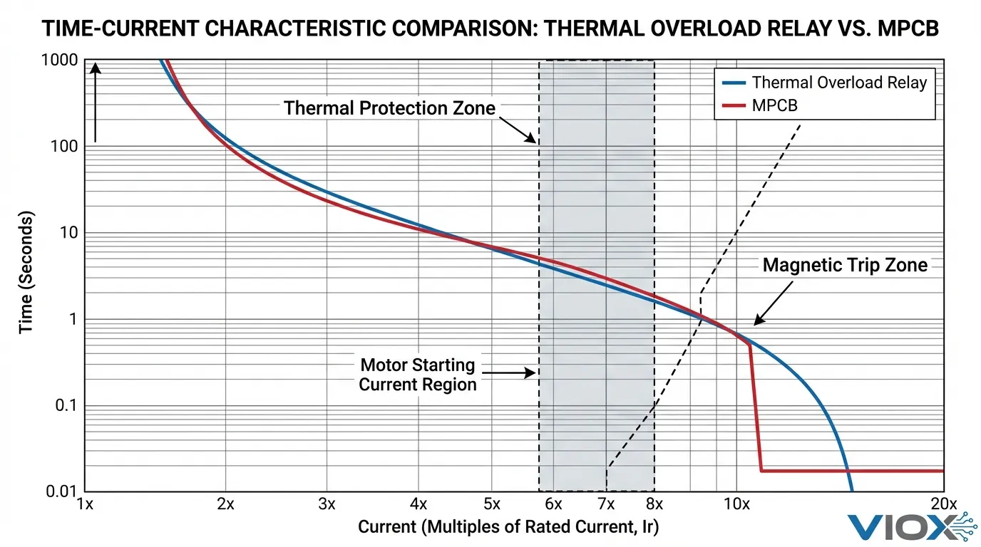
The fundamental principle behind thermal overload relays mirrors the thermal characteristics of electric motors themselves. Motors can tolerate brief overloads during startup—often drawing 600-800% of full-load current for several seconds—but sustained overcurrent conditions cause winding insulation degradation and eventual failure. Thermal overload relays are designed with inverse time-current characteristics that permit these transient surges while protecting against damaging sustained overloads.
How Thermal Overload Relays Work
The operation relies on differential thermal expansion. In bimetallic strip designs, two metals with different thermal expansion coefficients are bonded together. When current flows through the motor circuit, heat generation increases proportionally to I²R losses. This heat transfers to the bimetallic element, causing it to bend toward the metal with the lower expansion coefficient. Once the deflection reaches a predetermined threshold, it mechanically releases a trip mechanism that opens normally-closed contacts in the control circuit.
Eutectic alloy overload relays use a different approach. A heating element surrounds a eutectic alloy solder that holds a ratchet wheel in place. Under overload conditions, the solder melts at its precise eutectic temperature, releasing the ratchet and allowing a spring to rotate the trip mechanism. This design offers excellent repeatability and accuracy, particularly in applications with stable ambient temperatures.
Limitations of Thermal Overload Relays
Despite their reliability, thermal overload relays have inherent limitations that engineers must understand. They provide no short-circuit protection—if a phase-to-phase or phase-to-ground fault occurs, the resulting current can be 10-50 times the motor’s full-load rating, far exceeding the relay’s interrupting capacity. This necessitates an upstream circuit breaker or fuse rated for the available fault current.
Thermal overload relays also lack phase loss detection in basic models. Single-phasing—when one phase of a three-phase supply fails—causes the motor to draw excessive current in the remaining phases while producing reduced torque. Without dedicated phase failure protection, the motor can overheat and fail before the thermal overload trips. Additionally, thermal overload relays cannot manually disconnect the motor for maintenance; they only interrupt the control circuit, requiring the contactor to perform the actual load switching.
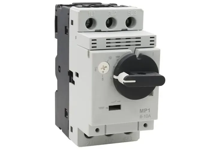
Understanding Motor Protection Circuit Breakers (MPCBs)
Motor Protection Circuit Breakers represent an evolution in motor protection technology, integrating multiple protective functions into a single compact device. An MPCB combines the thermal overload protection of a relay with the instantaneous short-circuit protection of a circuit breaker, plus manual switching capability and often phase failure detection. This integration addresses the limitations of traditional protection schemes while reducing panel complexity.
Dual Protection Mechanism
MPCBs employ a thermal-magnetic trip mechanism that provides two distinct layers of protection. The thermal element—typically an adjustable bimetallic strip—monitors current flow and trips the breaker when sustained overload conditions exceed the preset threshold. This thermal trip operates on an inverse time-current curve similar to thermal overload relays, allowing motor starting currents while protecting against prolonged overloads.
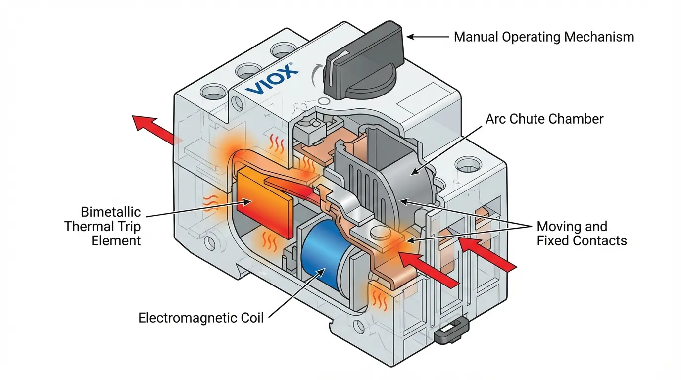
The magnetic trip element provides instantaneous protection against short circuits. When fault current exceeds a predetermined multiple of the rated current (typically 10-14 times), the magnetic field generated by the current actuates a trip mechanism within milliseconds. This rapid response prevents damage to motor windings, cables, and downstream equipment. The magnetic trip operates independently of temperature, ensuring reliable protection even in extreme ambient conditions.
Advanced Features in Modern MPCBs
Contemporary MPCBs incorporate features that extend beyond basic protection. Phase failure sensitivity detects voltage imbalance or complete phase loss, tripping the breaker before single-phasing can damage the motor. Adjustable trip settings allow precise matching to motor characteristics—most MPCBs offer current adjustment ranges of ±20-25% around the nominal rating, enabling one device to protect motors with slightly different full-load currents.
Many MPCBs include trip indication mechanisms that differentiate between thermal overload trips and magnetic short-circuit trips. This diagnostic capability accelerates troubleshooting by immediately identifying the fault type. Some advanced models feature auxiliary contacts for remote signaling, shunt trip coils for emergency shutdown integration, and undervoltage releases that prevent automatic restart after power restoration.
Comprehensive Comparison: Thermal Overload Relay vs. MPCB
| Feature | Thermal Overload Relay | Motor Protection Circuit Breaker (MPCB) |
|---|---|---|
| Overload Protection | Yes (thermal element) | Yes (adjustable thermal element) |
| Short-Circuit Protection | No (requires separate breaker) | Yes (integrated magnetic trip) |
| Phase Failure Detection | No (unless specialized model) | Yes (standard in most models) |
| Manual Switching | No (only trips control circuit) | Yes (manual ON/OFF operation) |
| Trip Response Time (Overload) | 5-30 seconds at 150% FLC | 5-30 seconds at 150% FLC |
| Trip Response Time (Short Circuit) | N/A | <10 milliseconds |
| Current Adjustment Range | Limited (often fixed class) | Wide (typically ±20-25%) |
| Installation Space | Requires contactor + relay + breaker | Single integrated device |
| Wiring Complexity | Higher (multiple components) | Lower (fewer connections) |
| Trip Indication | Basic (manual reset button) | Advanced (thermal/magnetic differentiation) |
| Typical Cost (per motor) | $15-50 (relay only, excludes breaker) | $60-200 (complete protection) |
| Reset Method | Manual or automatic | Manual only |
| Auxiliary Contacts | Yes (standard) | Optional (model-dependent) |
| Best Application | Multi-motor control, VFD outputs | Standalone motor protection, space-constrained panels |
When to Use Thermal Overload Relays
Thermal overload relays remain the optimal choice in specific applications where their characteristics align with system requirements. Variable frequency drive (VFD) applications often benefit from thermal overload relays on the output side. Since VFDs provide inherent short-circuit protection and current limiting, the MPCB’s magnetic trip function becomes redundant. Using a contactor with thermal overload relay on the VFD output provides motor-specific overload protection while allowing the VFD to manage fault conditions.
Multiple motor coordination scenarios favor thermal overload relays. When several motors operate from a common power source with individual control requirements, using contactors with thermal overload relays provides independent overload protection for each motor while sharing upstream short-circuit protection. This architecture reduces costs compared to individual MPCBs for each motor. The relay’s auxiliary contacts integrate seamlessly with PLC control systems, enabling sophisticated interlocking and sequencing logic.
Applications requiring specific trip classes may necessitate thermal overload relays. Trip class ratings (Class 10, 20, 30) define the maximum time allowed for the overload device to trip at 600% of full-load current. High-inertia loads like centrifugal fans or large flywheels require Class 20 or 30 protection to accommodate extended acceleration times. While some MPCBs offer adjustable trip classes, thermal overload relays provide a wider selection of specialized trip characteristics.
When to Use Motor Protection Circuit Breakers
MPCBs excel in applications where their integrated functionality provides tangible benefits. Space-constrained control panels benefit significantly from MPCB installation. By eliminating the separate circuit breaker and reducing the contactor-plus-relay footprint, MPCBs can reduce panel space requirements by 30-40%. This space efficiency translates to smaller enclosures, reduced material costs, and improved heat dissipation within the panel.
Standalone motor applications without complex control requirements are ideal MPCB candidates. Simple on-site motor control for pumps, compressors, or conveyors requires only start/stop functionality with comprehensive protection. An MPCB provides complete protection, manual switching, and fault indication in a single device, eliminating the need for separate components. The reduced wiring complexity decreases installation time and potential connection errors.
Three-phase motor protection particularly benefits from MPCBs with integrated phase failure detection. Single-phasing represents one of the most common motor failure modes, especially in industrial environments with aging infrastructure. MPCBs detect voltage imbalance or phase loss and trip before the motor sustains damage, providing protection that basic thermal overload relays cannot match. This feature alone justifies the MPCB premium in critical applications.
Maintenance accessibility considerations favor MPCBs in certain installations. The manual switching capability allows maintenance personnel to locally isolate motors without accessing remote disconnect switches or control panels. This local isolation improves safety during maintenance and troubleshooting. The clear trip indication—often with color-coded indicators differentiating thermal from magnetic trips—accelerates fault diagnosis and reduces downtime.
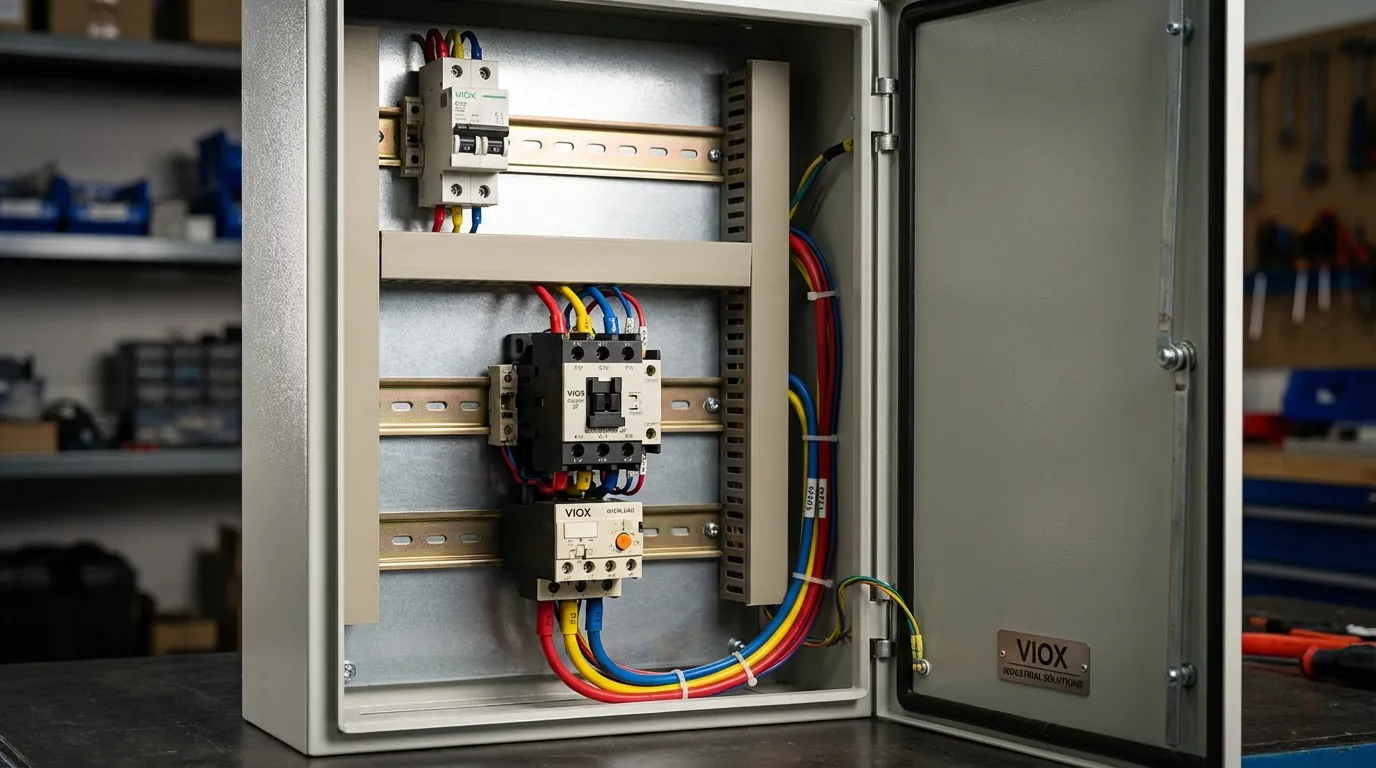
Installation and Wiring Considerations
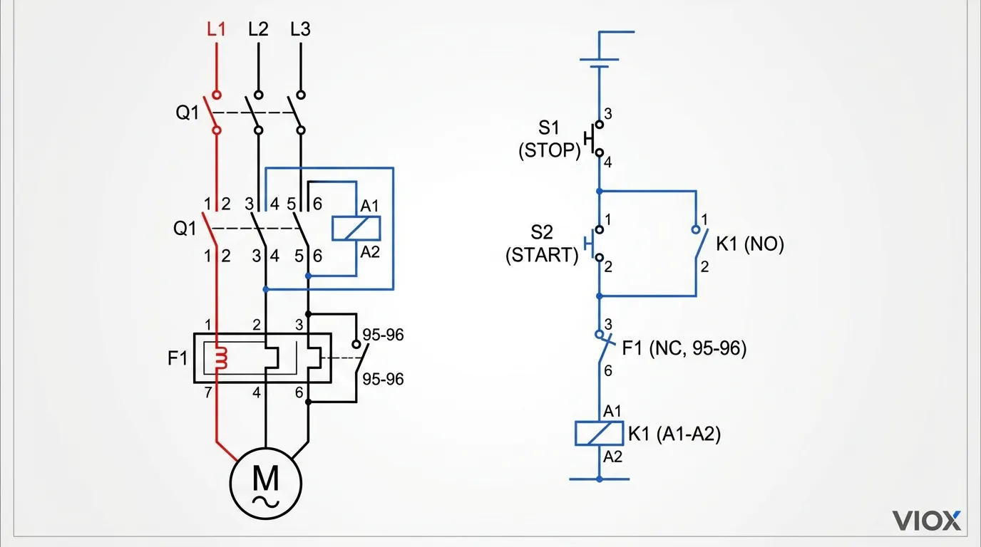
The installation approach differs significantly between thermal overload relays and MPCBs, affecting labor costs and system reliability. Thermal overload relay installations require three primary components: an upstream circuit breaker for short-circuit protection, a contactor for load switching, and the thermal overload relay itself. The circuit breaker connects to the line side of the contactor, the contactor’s load terminals connect to the overload relay’s input, and the overload relay’s output connects to the motor.
Control wiring adds complexity. The contactor coil circuit includes start/stop pushbuttons, the overload relay’s auxiliary contacts (wired in series for automatic trip), and often additional interlocking or indicating devices. Each connection point represents a potential failure mode, and troubleshooting requires understanding the interaction between multiple components. However, this complexity enables sophisticated control schemes with multiple motors, emergency stops, and remote monitoring.
MPCB installations simplify the power circuit dramatically. Line power connects directly to the MPCB input terminals, and the output connects directly to the motor—no intermediate devices required. For applications requiring remote control, an external contactor can be added downstream of the MPCB, but many installations use the MPCB’s manual operation exclusively. Some MPCBs offer optional motor operator attachments that enable remote switching while maintaining the integrated protection benefits.
The wiring time difference is substantial. Industry data suggests thermal overload relay installations require 30-50% more wiring time than equivalent MPCB installations when considering power connections, control wiring, and labeling. This labor differential often offsets the higher component cost of MPCBs, particularly in regions with high labor rates. Additionally, fewer connection points reduce the probability of wiring errors that could compromise protection or create safety hazards.
Cost Analysis: Total Ownership Perspective
Initial component costs tell only part of the story. A comprehensive cost analysis must consider procurement, installation, maintenance, and downtime costs over the equipment lifecycle. Thermal overload relay systems have lower component costs—a quality thermal overload relay costs $15-50, plus a contactor ($30-150) and circuit breaker ($20-80), totaling $65-280 depending on motor size and specifications. However, installation labor typically adds $100-200 per motor point, and the larger panel space may increase enclosure costs by $50-100 per motor.
MPCB systems have higher component costs, ranging from $60-200 for motors up to 15 kW, but installation labor is typically 30-40% lower due to simplified wiring. Panel space savings can reduce enclosure costs, and the reduced component count lowers inventory complexity—one MPCB model with adjustable settings can replace multiple fixed-rating thermal overload relays. Over a 10-year lifecycle, MPCBs often demonstrate lower total cost of ownership despite higher initial prices.
Maintenance costs favor MPCBs in most scenarios. The integrated design eliminates potential compatibility issues between components from different manufacturers. Troubleshooting is faster due to integrated trip indication, and the manual reset requirement (versus automatic reset available in some thermal overload relays) prevents repeated restart attempts that could damage motors. However, MPCB failure requires complete device replacement, while thermal overload relay systems allow individual component replacement.
Standards and Compliance Considerations
Both thermal overload relays and MPCBs must comply with international standards, but the applicable standards differ. Thermal overload relays fall under IEC 60947-4-1 (Contactors and Motor-Starters) in international markets and UL 508 (Industrial Control Equipment) in North America. These standards specify thermal characteristics, trip class ratings, ambient temperature compensation, and coordination with contactors. Understanding these standards ensures proper device selection and system coordination.
MPCBs are governed by IEC 60947-2 (Circuit-Breakers) internationally and UL 508 Type E motor circuit protectors in North America. These standards define breaking capacity, making capacity, coordination with downstream devices, and protection characteristics. The distinction is important: an MPCB certified to IEC 60947-2 provides verified short-circuit interrupting capability, while a thermal overload relay certified only to IEC 60947-4-1 does not.
Coordination studies become critical when selecting between these devices. Proper coordination ensures that the protection device closest to the fault operates first, minimizing disruption to other circuits. Circuit protection coordination requires analyzing time-current curves for all protective devices in the circuit path. MPCBs simplify coordination by integrating overload and short-circuit protection in one device with a single time-current curve, while thermal overload relay systems require coordinating the relay’s overload curve with the upstream breaker’s short-circuit curve.
Practical Selection Framework
Choosing between thermal overload relays and MPCBs requires evaluating multiple factors specific to your application. Start by assessing control complexity. If the motor requires only local start/stop with no remote control, interlocking, or sequencing, an MPCB provides complete protection in the simplest package. If the application involves multiple motors with interdependent operation, coordinated starting sequences, or integration with PLCs, thermal overload relays with contactors offer greater flexibility.
Evaluate available panel space. Measure the physical dimensions required for each approach, considering not just the devices themselves but also wire bending space and heat dissipation clearances. In retrofit applications where panel space is constrained, MPCBs may be the only viable option. For new panel designs, calculate the total enclosure cost difference—sometimes a slightly larger enclosure with thermal overload relays costs less than a compact enclosure with MPCBs.
Consider maintenance capabilities at the installation site. MPCBs require less electrical expertise for basic troubleshooting due to integrated trip indication and simpler wiring. Sites with limited maintenance staff or high technician turnover may benefit from MPCB simplicity. Conversely, facilities with experienced electricians and comprehensive spare parts inventories may prefer the component-level serviceability of thermal overload relay systems.
Analyze motor criticality and failure costs. For critical motors where downtime costs hundreds or thousands of dollars per hour, MPCB phase failure protection provides valuable insurance against single-phasing damage. For non-critical motors where failure causes minimal disruption, basic thermal overload protection may suffice. Calculate the expected value of avoided failures to justify the MPCB premium.
Future Trends in Motor Protection
The motor protection landscape continues evolving with advances in electronics and connectivity. Electronic overload relays represent a middle ground between traditional thermal overload relays and MPCBs. These devices use current transformers and microprocessor-based algorithms to provide precise overload protection with advanced features like ground fault detection, phase imbalance monitoring, and communication capabilities. Electronic overload relays still require separate short-circuit protection but offer superior accuracy and diagnostics compared to thermal devices.
Smart MPCBs with embedded communication protocols are gaining traction in Industry 4.0 environments. These devices provide real-time current monitoring, predictive maintenance alerts based on thermal accumulation, and remote trip/reset capabilities via Ethernet, Profibus, or Modbus protocols. The data generated enables condition-based maintenance strategies that reduce unplanned downtime and extend motor life. Integration with building management systems or SCADA platforms provides unprecedented visibility into motor health and energy consumption.
Solid-state motor protection eliminates mechanical components entirely, using power electronics for both protection and switching. While currently limited to specialized applications due to cost and heat dissipation challenges, solid-state devices offer microsecond response times, infinite adjustment resolution, and complete immunity to mechanical wear. As semiconductor technology advances and costs decline, solid-state protection may eventually replace both thermal overload relays and conventional MPCBs in demanding applications.
FAQ Section
Q: Can I replace a thermal overload relay with an MPCB directly?
A: Not always. If your current setup uses a contactor for remote control or motor reversing, you’ll need to retain the contactor and use the MPCB only for protection, or select an MPCB with remote operating capability. Verify that the MPCB’s breaking capacity meets or exceeds the available fault current at the installation point.
Q: Why do thermal overload relays have different trip classes?
A: Trip classes (10, 20, 30) define the maximum time the relay can take to trip at 600% of rated current. Class 10 trips in 10 seconds or less, suitable for standard motors. Class 20 (20 seconds) and Class 30 (30 seconds) accommodate high-inertia loads with longer acceleration times. Using the wrong class can cause nuisance tripping or inadequate protection.
Q: Do MPCBs work with variable frequency drives?
A: MPCBs can be installed upstream of VFDs for input protection, but they’re generally not recommended on VFD outputs. The VFD’s PWM output waveform can cause nuisance tripping in magnetic trip elements. Use thermal overload relays or the VFD’s built-in motor protection for output-side protection.
Q: How do I size an MPCB for a motor?
A: Select an MPCB with an adjustable current range that includes the motor’s full-load current (FLC) from the nameplate. Set the MPCB’s thermal adjustment to match the FLC. For motors with high starting currents, verify that the MPCB’s magnetic trip threshold (typically 10-14× rated current) won’t cause nuisance tripping during starts.
Q: Can thermal overload relays detect phase loss?
A: Basic thermal overload relays cannot reliably detect phase loss. Some advanced models include phase failure detection, but this feature is standard in most MPCBs. Single-phasing causes motors to draw excessive current in the remaining phases, which may eventually trip a thermal overload, but often not before motor damage occurs.
Q: What’s the typical lifespan of an MPCB vs. thermal overload relay?
A: Both devices have mechanical lifespans of 10,000-100,000 operations depending on load conditions. MPCBs typically have shorter electrical lifespans when interrupting high fault currents repeatedly, as the arc interruption mechanism experiences wear. Thermal overload relays only interrupt control circuits with minimal current, extending their electrical life. Proper maintenance and operation within ratings ensures 15-20 years of service for both.
Conclusion
The choice between thermal overload relays and motor protection circuit breakers ultimately depends on your specific application requirements, budget constraints, and long-term maintenance strategy. Thermal overload relays excel in complex control systems requiring remote operation, multiple motor coordination, or specialized trip characteristics, particularly when paired with contactors and appropriate upstream protection. Their lower component costs and component-level serviceability make them attractive for large installations with experienced maintenance staff.
MPCBs provide comprehensive protection in a compact, integrated package that simplifies installation, reduces panel space, and offers superior protection against phase failures and short circuits. The higher initial cost is often justified by reduced installation labor, smaller enclosures, and faster troubleshooting. For standalone motors, space-constrained applications, or installations with limited maintenance expertise, MPCBs represent the modern standard in motor protection.
As motor protection technology continues advancing toward electronic and smart solutions, both traditional thermal overload relays and conventional MPCBs will gradually incorporate digital features, communication capabilities, and predictive maintenance functions. Understanding the fundamental differences between these protection philosophies positions engineers to make informed decisions today while preparing for the connected, data-driven motor protection systems of tomorrow.
For comprehensive guidance on motor protection strategies and industrial control panel design, VIOX Electric offers a complete range of protection devices, technical support, and application engineering expertise to ensure your motors operate safely and efficiently.
