Quick Answer: Neutral Bar vs Grounding Bar
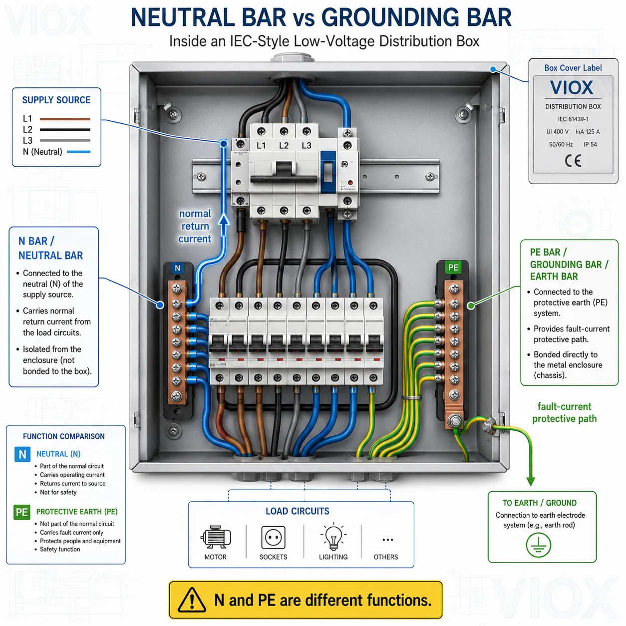
A neutral bar connects neutral conductors and normally carries return current back to the supply source. A grounding bar, also called a ground bar, earth bar, or PE bar, connects protective earth conductors and normally carries current only during fault conditions.
In main service equipment, neutral and ground may be bonded at the designated bonding point. In downstream subpanels or distribution boards, the neutral bar normally remains isolated from the enclosure, while the grounding bar is bonded to the enclosure.
That one rule prevents normal neutral current from flowing through protective earth paths, metal enclosures, conduit, cable shields, DIN rail assemblies, or equipment frames.
Neutral Bar vs Grounding Bar in One Table
| Feature | Neutral bar | Grounding bar / earth bar / PE bar |
|---|---|---|
| Primary function | Collects neutral conductors and provides the normal return path | Collects protective earth conductors and provides a protective fault path |
| Normal current | Yes, it can carry load return current during normal operation | No, it should not carry normal load current |
| Fault role | Part of the grounded current-carrying system where a neutral is used | Helps create an effective fault-current path so protection can operate |
| IEC wording | N bar | PE bar or earth bar |
| North American wording | Neutral bus bar | Ground bar or equipment grounding bar |
| Typical isolation | Isolated from enclosure in downstream panels | Bonded to the metal enclosure where required |
| Typical conductor color | White or gray in North American systems; blue in many IEC systems | Bare/green in North America; green-yellow in IEC systems |
| Terminal rule | Usually one neutral conductor per terminal, according to panel listing | Multiple PE conductors may be permitted only if the bar and terminal listing allow it |
| Wrong-use risk | Neutral current may energize protective parts if bonded incorrectly | Exposed metal parts may carry normal current if used as a neutral path |
For distribution-box context, VIOX’s Distribution Box and Selection Guide explains how MCBs, RCBOs, busbars, neutral bars, earth bars, and SPDs fit together inside a modular box.
What Is a Neutral Bar?
A neutral bar is a conductive busbar or terminal assembly used to connect the neutral conductors of multiple circuits. In a single-phase AC circuit, the neutral conductor normally completes the circuit by carrying return current back toward the supply source. In three-phase systems, neutral current depends on load balance and harmonic content, but the neutral conductor is still a current-carrying conductor when used.
In panel drawings and IEC-style distribution boards, the neutral bar is often labeled:
- N
- N bar
- neutral busbar
- neutral terminal bar
- neutral link
A neutral bar is not a spare grounding point. It is part of the normal current-carrying circuit. That is why neutral termination quality matters: loose neutral connections can cause overheating, unstable voltage, equipment malfunction, and serious safety hazards.
What Is a Grounding Bar or Earth Bar?
A grounding bar is a conductive bar used to connect protective earth conductors. In IEC terminology, it is commonly called a PE bar or earth bar. In North American terminology, it may be called a ground bar or equipment grounding bar.
Its purpose is safety, not normal load return. The grounding bar connects:
- protective earth conductors
- equipment grounding conductors
- bonding conductors
- metallic enclosure bonding points
- SPD earth leads where applicable
- cabinet doors, mounting plates, or removable metal parts where required by design
During a fault, the grounding/PE system provides a low-impedance protective path so the appropriate protective device can operate. In real engineering terms, the goal is not simply to "send current into the earth." The fault-current path must return effectively to the source or protective system so breakers, fuses, RCDs, RCBOs, or other protective devices can respond as intended.
If the ground bar must be insulated from a mounting surface for a specific design, use hardware designed for that purpose. VIOX’s guide on what a ground bar insulator kit is is a useful follow-up for that hardware boundary.
NEC vs IEC Terminology: Neutral, Ground, N, and PE
Different markets use different language for the same safety concepts. Mixing the words without understanding the function is a common source of design mistakes.
| Term | NEC / North American wording | IEC / international wording | Function |
|---|---|---|---|
| Neutral bar | Neutral bus bar | N bar | Carries normal return current where a neutral conductor is used |
| Grounding bar | Ground bar / equipment grounding bar | PE bar / earth bar | Connects protective earth conductors and fault-current paths |
| Neutral conductor | Grounded conductor | N conductor | Current-carrying return path |
| Ground conductor | Equipment grounding conductor | PE conductor | Protective fault path, normally not current-carrying |
| Neutral-ground bond | Main bonding jumper or system bonding jumper | N-PE bond at defined system point | Establishes the designed reference and fault path at the permitted point |
The names change by region, but the principle does not: N carries normal return current. PE is the protective path. They must not be casually mixed.
Main Panel vs Subpanel: When Are Neutral and Ground Bonded?
The bonding rule is the point where many installation errors begin.
Main Service Equipment
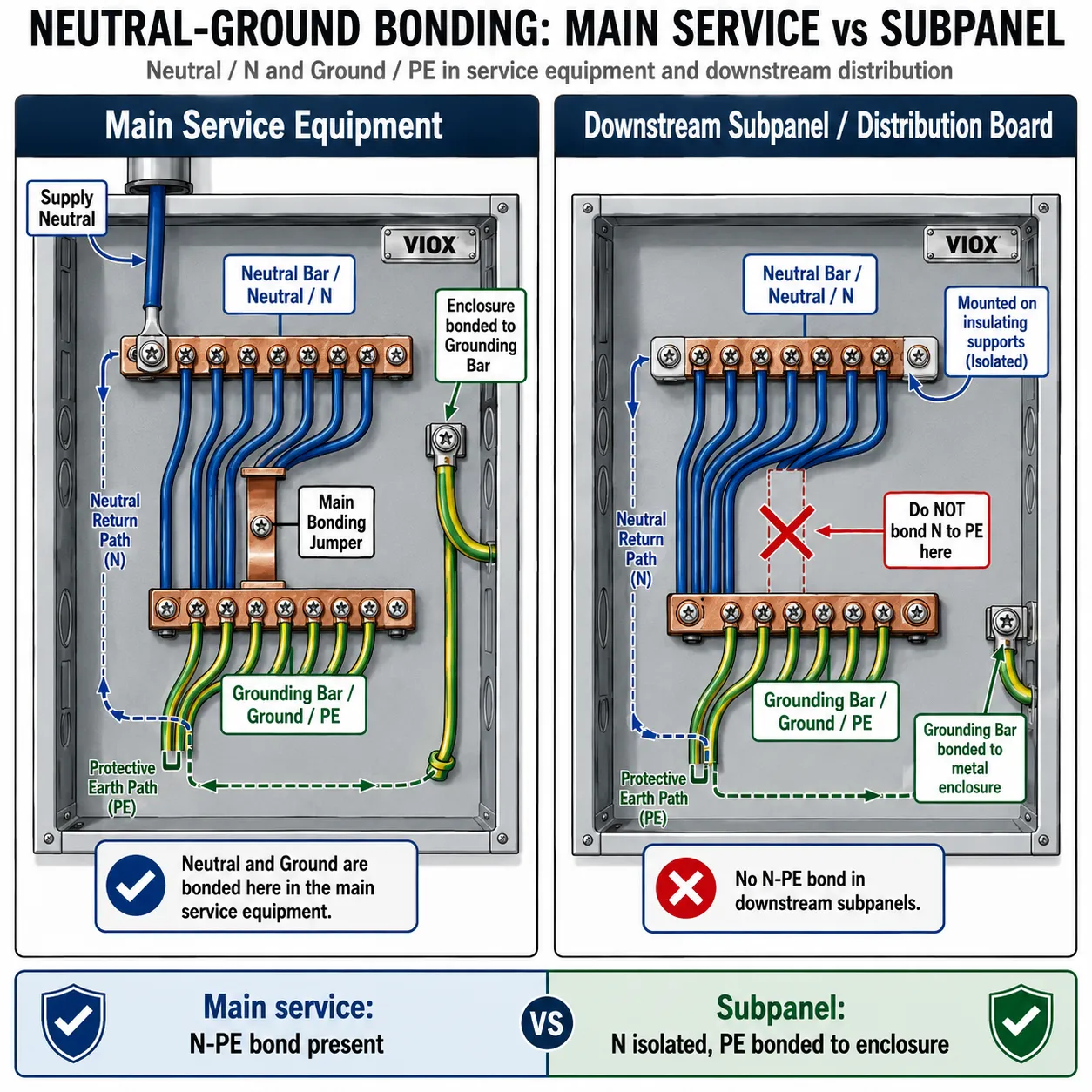
In North American service equipment, the neutral and equipment grounding conductors are bonded at the designated service disconnect or service equipment bonding point. This is normally done with a main bonding jumper, bonding screw, or bonding strap approved for that equipment.
This bond connects the grounded conductor system, equipment grounding system, enclosure, and grounding electrode system according to the installation rules for that service.
The important detail is that this bond belongs at the designated point, not wherever it is convenient.
Downstream Subpanels and Distribution Boards
In a downstream subpanel or distribution board, the neutral bar normally remains isolated from the enclosure. The grounding bar is bonded to the enclosure.
That separation prevents normal neutral current from flowing on:
- protective earth conductors
- metal conduits
- cable armor
- enclosure bodies
- equipment frames
- DIN rails and mounting structures
If neutral and ground are bonded again downstream, the installation creates parallel return paths. Current that should stay on the neutral conductor can flow through grounding paths and exposed metalwork.
Separately Derived Systems
Transformers, generators, UPS systems, and some inverter systems may create separately derived systems with their own bonding rules. The principle remains the same: bond only at the point required by the system design and applicable code.
IEC View: N Bar, PE Bar, TN-S, TN-C-S, TT, and IT Systems
IEC-style installations often discuss neutral and earth bars through the earthing arrangement. This is especially important for global B2B buyers, panel builders, and OEMs because the same enclosure layout may be adapted for different markets.
| System | Neutral / PE arrangement | What it means for N bar and PE bar |
|---|---|---|
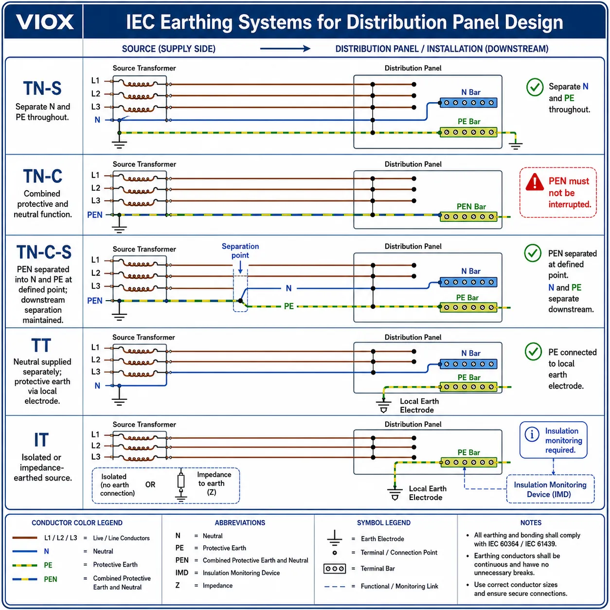
| TN-S | Neutral and protective earth are separate throughout the installation | Use separate N and PE bars; PE bar bonds to exposed conductive parts |
| TN-C | Neutral and protective earth are combined throughout the relevant section as a PEN conductor | No separate N bar and PE bar exist in the combined section; the PEN conductor must not be interrupted, and RCD application is limited unless the system is converted to a separated arrangement downstream |
| TN-C-S | PEN conductor is separated into N and PE at a defined point | After separation, N and PE must remain separate downstream |
| TT | Installation has its own local earth electrode; neutral is supplied separately | PE bar connects to local earthing system; RCD protection is often central to fault protection |
| IT | System is isolated from earth or earthed through impedance | PE bar remains essential; insulation monitoring and first-fault behavior affect design |
This is where an IEC panel builder must be careful. A layout that works for TN-S may not automatically fit TT or IT without reviewing the protection method, RCD/RCBO strategy, SPD mode, and local wiring rules.
In practice, once a PEN conductor is separated into distinct N and PE conductors, the downstream installation is no longer pure TN-C; it becomes TN-C-S from that separation point. From there, N and PE must remain separated downstream unless a specific separately derived system or local rule requires a new defined bonding point.
For naming boundaries between enclosures, boxes, and boards, see Electrical Enclosure vs Distribution Box vs Distribution Board.
Why N/PE Separation Matters for RCDs, RCBOs, and SPDs
Neutral and PE separation is not just a wiring neatness issue. It directly affects protective devices.
RCDs and RCBOs
An RCD or RCBO compares current flowing out and returning through the intended live conductors. If neutral current leaks into the PE path downstream of the device, the residual-current measurement can become unreliable or trip unexpectedly.
Common symptoms of bad N/PE handling include:
- nuisance tripping
- RCBOs that trip only when certain loads operate
- unexpected voltage on metalwork
- current measured on PE conductors during normal operation
- difficult fault diagnosis because neutral and protective paths are mixed
If the article reader is comparing protective concepts, the VIOX guide on grounding vs GFCI vs surge protection is the right supporting page.
SPDs
Surge protective devices depend on short, direct protection paths to N and/or PE depending on the protection mode. If the PE bar is poorly located, poorly bonded, or mixed with neutral incorrectly, the surge discharge path can become longer or less predictable.
For SPD installation, the important practical rules are:
- connect the SPD to the correct N and PE points for the earthing system
- keep PE leads short and direct according to manufacturer instructions
- avoid unnecessary loops
- do not use the neutral bar as a substitute for the PE bar
- verify N-PE protection mode where required
For detailed surge-protection installation risks, see SPD Installation Mistakes and How to Fix Them.
Common Wiring Mistakes in Distribution Boxes
| Mistake | Why it is dangerous | Better practice |
|---|---|---|
| Bonding neutral and ground in a downstream subpanel | Neutral current can flow on grounding paths, metal enclosures, conduit, and equipment frames | Keep neutral isolated and bond the PE/grounding bar to the enclosure |
| Putting neutral and ground under the same terminal | Loose connection, overheating, and code/listing violation risk | Use terminals according to the panel listing and manufacturer’s instructions |
| Missing the main bonding jumper | Fault current may not clear correctly and the enclosure may not be properly bonded | Bond only at the designated main bonding point or separately derived system point |
| Treating the PE bar as a neutral bar | Exposed metal parts may carry normal return current | Keep N and PE functions separate |
| Ignoring SPD PE connection | Surge discharge path becomes too long, indirect, or ineffective | Keep SPD PE lead short and direct according to the wiring diagram |
| Using an undersized or overcrowded bar | Terminations overheat, loosen, or become difficult to inspect | Select a bar with adequate current rating, terminal capacity, and conductor range |
| Not bonding removable metal parts | Doors or mounting plates may not have a reliable protective path | Use approved bonding straps or conductors where required |
| Assuming color is enough for identification | Wire colors vary by region and old installations may be inconsistent | Verify by function, drawing, test method, and labeling |
For broader connection hardware selection, the terminal block product range and terminal block selection guide are useful when designing control panels or distribution assemblies.
How to Identify Neutral and Grounding Bars in a Panel
Do not rely on one clue alone. Identify bars by function, mounting, bonding, labeling, and wiring.
Neutral Bar Identification
A neutral bar is typically:
- labeled N, Neutral, or similar
- connected to neutral conductors
- isolated from the enclosure in downstream panels
- connected to the service neutral or supply neutral path
- arranged so each neutral conductor uses the permitted terminal method
In a North American panel, neutral conductors are often white or gray. In many IEC systems, neutral conductors are blue. Do not use color as the only test.
Grounding Bar / PE Bar Identification
A grounding bar or PE bar is typically:
- labeled PE, Earth, Ground, or GND
- bonded to the metal enclosure where required
- connected to protective earth conductors
- connected to bonding conductors for enclosure parts
- used as the reference point for SPD PE connection where the design requires it
In North America, grounding conductors are often bare copper or green. In IEC systems, PE conductors are commonly green-yellow.
The Safe Inspection Sequence
Before energizing or modifying a panel, a qualified person should verify:
- whether the panel is service equipment, a subpanel, a distribution board, or a separately derived system point
- where the N-PE bond is permitted or required
- whether the neutral bar is isolated from the enclosure where required
- whether the PE bar is bonded to the enclosure
- whether RCDs, RCBOs, and SPDs are connected to the intended N/PE points
- whether conductor terminations match the panel and bar listing
- whether labels match the drawings
Field Check: Three Tests That Reveal a Bad N-PE Bond
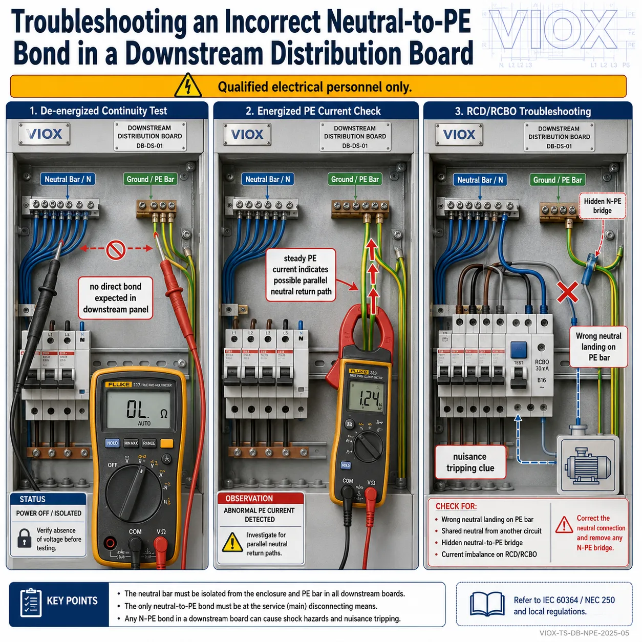
These checks are for qualified electrical personnel only. They are useful because incorrect N-PE bonding often looks visually acceptable until the circuit is measured.
- De-energized continuity check. With the downstream panel isolated and verified de-energized, measure between the neutral bar and PE bar. In a subpanel or downstream distribution board where N and PE should be separated, they should not show a direct bond. A low-resistance reading suggests a bonding screw, strap, shared terminal, or connected load path needs investigation.
- PE current check under load. With the system energized and normal loads operating, clamp the main PE conductor or grounding conductor feeding the downstream panel. In a correctly separated system, normal load current should not be returning through PE. Measurable amperes on PE under steady load often indicate parallel neutral return paths or an unintended N-PE connection.
- RCD/RCBO symptom check. If an RCD or RCBO trips only when a specific branch circuit or load is connected, isolate that circuit and check whether neutral has been landed on the wrong bar or tied to PE downstream of the device. In panel troubleshooting, nuisance tripping is often the symptom; a hidden N-PE bridge is the cause.
For enclosure layout decisions, see VIOX’s guide to electrical enclosure mounting plates and the distribution box product page.
FAQ
What is the main difference between a neutral bar and a grounding bar?
A neutral bar connects neutral conductors and normally carries return current. A grounding bar connects protective earth or equipment grounding conductors and normally carries current only during fault conditions.
Is a grounding bar the same as an earth bar or PE bar?
In many IEC-style systems, yes. Grounding bar, earth bar, and PE bar usually refer to the bar used for protective earth conductors. The exact terminology depends on the market and wiring standard.
Can neutral and ground be on the same bar?
Only at the defined bonding point, such as service equipment or a separately derived system point where the applicable code and equipment design allow it. Downstream, treat N and PE as separate unless the project documentation says otherwise.
Why must neutral and ground be separated in a subpanel?
Because a second N-PE bond creates parallel return paths. The quick field clue is PE current during normal load operation; PE should not be carrying steady neutral return current.
Does the ground bar carry current?
Under normal conditions, it should not carry load current. It may carry current during a fault, surge event, leakage event, or abnormal condition depending on the protective system.
Does the neutral bar need to be insulated?
In downstream panels, usually yes: the neutral bar is mounted on insulating supports so it does not bond to the enclosure. At the defined main bonding point, the arrangement is intentionally different.
What is the IEC name for a ground bar?
The common IEC-style term is PE bar or earth bar. PE means protective earth.
What happens if I use the PE bar as a neutral bar?
You turn protective metalwork into part of the normal return path. That is exactly what PE is designed to avoid.
How does this affect SPD installation?
SPDs need a correct and short connection to PE and/or N depending on the protection mode and earthing system. Poor PE bar location, long leads, or incorrect N/PE bonding can reduce surge protection effectiveness.
Should a neutral bar and grounding bar be selected like terminal blocks?
They should be selected by conductor size, current rating, terminal capacity, material, mounting method, insulation requirements, and the panel’s listing or design specification. They are not generic strips of metal.
Conclusion
The neutral bar and grounding bar may look similar, but they do different jobs. The neutral bar is part of the normal current return path. The grounding bar, PE bar, or earth bar is part of the protective fault path and bonding system.
For a residential main panel/subpanel, the key question is where neutral and ground are bonded. For IEC distribution boards and panel-builder applications, the key question is how N and PE are separated under TN-S, TN-C-S, TT, or IT earthing rules.
The safest design approach is simple: keep N and PE functions distinct, bond them only at the permitted point, terminate conductors according to the panel listing, and route RCD/RCBO/SPD connections according to the actual system design.
