직접적인 답변: MCCB 내부에는 무엇이 있는가?
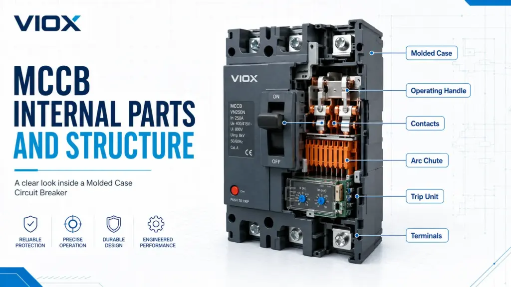
MCCB(배선용 차단기)는 몰드 절연 케이스, 고정 및 가동 접점, 조작 기구, 트립 장치, 아크 슈트, 전원 및 부하 단자로 구성되며, 보조 접점, 션트 트립, 알람 접점, 부족전압 트립 장치, 모터 조작 장치와 같은 선택적 액세서리를 포함합니다.
이러한 부품들은 상호 작용하여 정상 전류를 통전하고, 과부하 또는 단락 상태를 감지하며, 접점을 개방하고, 아크를 소멸시키며, 차단기의 정격 용량 내에서 결함이 발생한 회로를 분리합니다.
기본적인 정의, 정격 및 적용 분야를 먼저 확인해야 한다면 VIOX의 MCCB란 무엇인가요? 가이드를 읽어보십시오. 이 페이지는 MCCB 내부 구조, 부품 명칭 및 구성 요소의 기능에 중점을 둡니다.
한눈에 보는 MCCB 내부 구조
| MCCB 부품 | 주요 기능 | 왜 중요한가 |
|---|---|---|
| 몰드형 절연 케이스 | 내부 부품 고정 및 절연 | 기계적 지지 및 전기적 절연 제공 |
| 조작 핸들 | 수동 ON/OFF/RESET 조작 | 현장 제어 및 상태 표시 기능 제공 |
| 작동 메커니즘 | 축적된 기계적 에너지를 이용한 접점 개폐 | 트립 시 신속한 접점 분리 보장 |
| 고정 접점 및 가동 접점 | 전류 통전 및 차단 | 접점 재질 및 압력이 발열과 내구성에 미치는 영향 |
| 아크 슈트 | 아크 분할, 냉각 및 소호 | 안전한 단락 차단을 위한 핵심 요소 |
| 트립 장치 | 과부하 및 단락 감지 | 보호 동작 특성 결정 |
| 터미널 | 케이블 또는 버스바 연결 | 연결 품질이 온도 상승 및 신뢰성에 미치는 영향 |
| 액세서리 구획 | 제어 및 신호 액세서리 수용 | 원격 트립, 상태 피드백, 인터록 및 자동화 기능 제공 |
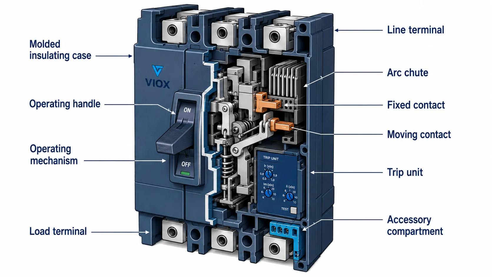
MCCB 부품도: 표시 항목
유용한 배선용 차단기(MCCB) 다이어그램에는 다음 섹션이 라벨과 함께 표시되어야 합니다:
전원측 단자다이어그램은 단순히 외함만을 보여주어서는 안 됩니다. MCCB 내부 구조도의 가치는 전류의 흐름, 접점이 열리는 위치, 아크가 소멸되는 지점, 그리고 트립 유닛이 어떻게 기구를 작동시키는지를 설명하는 데 있습니다.
MCCB의 일반적인 내부 섹션은 다음과 같습니다.
몰드 케이스는 MCCB의 외부 절연체입니다. 이 명칭은 제품의 이름에서 유래되었습니다.
케이스는 다음과 같은 여러 기능을 수행합니다:
- 내부 통전 부품을 지지합니다.
- 전기적 절연을 제공합니다.
- 먼지 및 우발적인 접촉으로부터 메커니즘을 보호합니다.
- 내부 이격 거리를 유지합니다.
- 제품 설계 내에서 고장 차단 시 발생하는 응력을 억제하는 데 도움을 줍니다.
몰드 케이스는 단순한 플라스틱 덮개가 아닙니다. 실제 고장 상황에서 차단기 본체는 장치 정격 내에서 열, 압력, 기계적 충격 및 아크 차단 응력을 견뎌야 합니다.
조작 핸들
핸들은 MCCB의 외부로 노출된 제어 부품입니다. 일반적으로 차단기의 상태가 ON, OFF 또는 TRIPPED(트립) 상태인지 표시합니다.
많은 MCCB에서 트립 위치는 OFF 위치와 정확히 일치하지 않습니다. 작업자는 다시 ON으로 전환하기 전에 핸들을 OFF 위치로 완전히 이동시켜야 할 수 있습니다. 이는 재투입 전 내부 래치 메커니즘을 초기화하는 데 도움이 됩니다.
핸들은 다음과 같은 용도로도 유용합니다:
- 현장 격리
- 수동 전환
- 유지보수 식별
- 액세서리 또는 핸들 설계에 따른 잠금 장치 부착
3. 작동 메커니즘
조작 기구는 기계적 에너지를 저장하고 방출하여 접점을 개폐합니다. 트립 발생 시, 사용자가 핸들을 잡고 있더라도 기구는 접점을 신속하고 확실하게 분리해야 합니다.
주요 기구 기능은 다음과 같습니다:
- 스냅 동작 개폐
- 적절한 설계에서의 트립 프리(trip-free) 동작
- 접점 압력 제어
- 트립 장치와 접점 시스템 간의 연동
- 트립 후 복귀
이것이 MCCB가 단순한 대형 스위치가 아닌 이유 중 하나입니다. MCCB는 내부 해제 기구를 갖춘 보호용 개폐 장치입니다.
4. 고정 및 가동 접점
고정 및 가동 접점은 정상 작동 중에 전류를 흐르게 합니다. MCCB가 트립되거나 OFF 상태로 전환되면 이 접점들은 분리됩니다.
접점 설계는 다음 사항에 영향을 미칩니다:
- 온도 상승
- 접촉 저항
- 전기적 내구성
- 단락 차단 성능
- 심각한 결함 조건 하에서의 용착 위험
높은 고장 전류가 발생하면 접점 분리 시 아크가 생성됩니다. 이 아크는 아크 슈트와 내부 아크 경로에 의해 제어되어야 합니다.
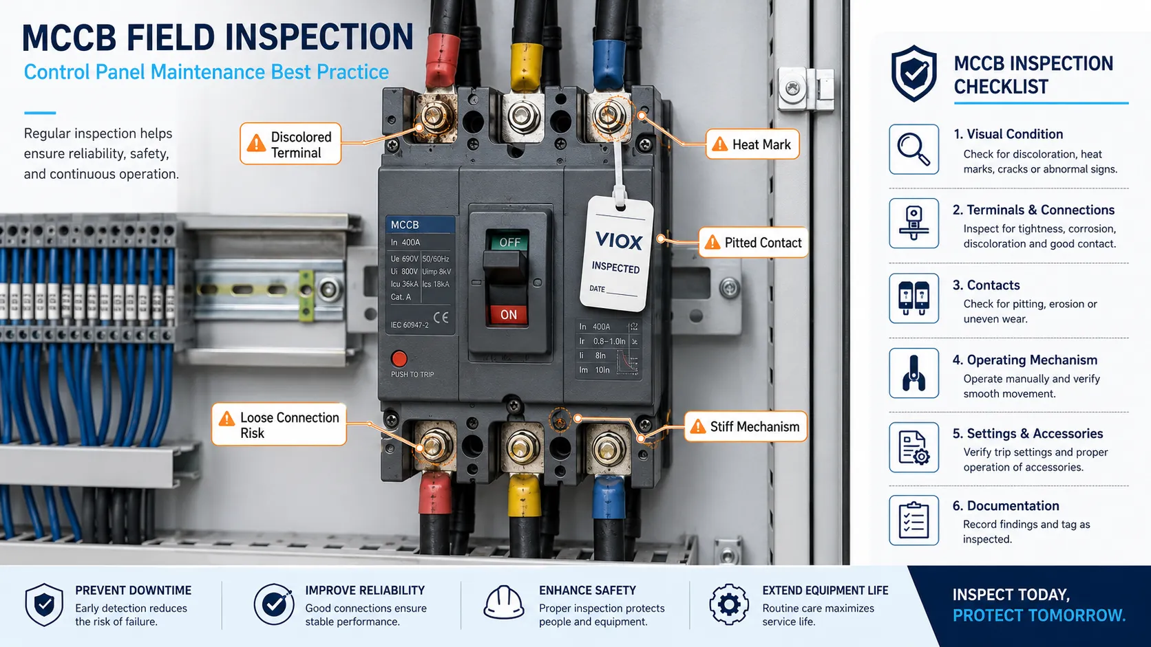
실제 배전반 점검 시 가장 우려되는 징후는 종종 눈에 띄는 외부 손상이 아닙니다. 단자 변색, 연결 부위 근처의 열 흔적, 접점의 피팅(pitting) 현상, 뻑뻑한 조작 메커니즘, 또는 심각한 결함을 차단한 후 기계적 일관성이 느껴지지 않는 차단기와 같은 작지만 심각한 내부 증상들입니다. 이러한 증상들은 여기서 논의된 접점, 단자, 메커니즘, 트립 유닛, 아크 슈트와 같은 동일한 내부 부품들의 문제점을 나타냅니다.
5. 아크 슈트 및 아크 차단 구조
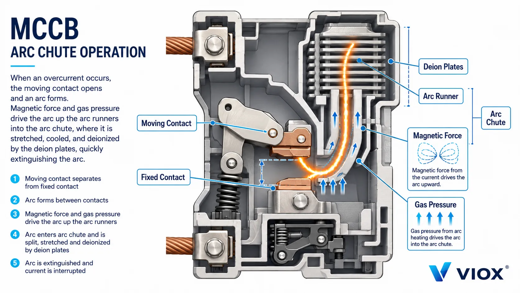
아크 슈트는 MCCB의 가장 중요한 내부 부품 중 하나입니다. 부하 또는 고장 전류 상태에서 접점이 분리될 때 그 사이에 아크가 형성됩니다. 아크 슈트는 아크를 더 작은 조각으로 분할하고, 길이를 늘리고, 냉각하여 소멸을 돕습니다.
아크가 우연히 아크 슈트로 이동하는 것은 아닙니다. 많은 차단기 설계에서 전류 경로, 접점 형상, 아크 러너 및 자기력은 아크를 접점 영역에서 멀리 떨어뜨려 분할판(splitter plates)으로 유도하는 역할을 합니다. 전류가 상승하면 아크 경로 주변의 전자기력이 아크 루트를 아크 러너를 따라 밀어냅니다. 동시에 아크 챔버 내부의 뜨거운 가스 압력이 아크를 이동시키고 늘리는 데 도움을 줍니다. 아크가 소호 그리드에 진입하면 더 작은 아크 세그먼트로 분할되고 냉각되며, 전류가 차단될 때까지 에너지를 잃게 됩니다.
적절한 아크 제어가 없으면 차단기는 단락 전류를 안전하게 차단할 수 없습니다.
아크 차단 구조에는 다음이 포함될 수 있습니다:
- 아크 러너(Arc runners)
- 소호 그리드(deion plates)
- 아크 소호판
- 아크 챔버
- 제품 설계에 따라 가스 발생 또는 내열성 소재 사용
- 설계에 따른 배기 경로
아크 슈트 설계는 차단 용량과 밀접한 관련이 있습니다. 이것이 동일한 정격 전류를 가진 두 개의 MCCB라도 동일한 고장 레벨에 적합하지 않을 수 있는 이유입니다.
다음과 같은 정격 용어에 대해서는 Icu, Ics, Icw및 Icm, VIOX의 회로 차단기 정격 가이드를 참조하십시오..
6. 트립 유닛
트립 유닛은 MCCB의 보호 두뇌 역할을 합니다. 비정상적인 전류를 감지하고 필요 시 조작 기구를 해제합니다.
열-자기식 트립 장치
열동-전자식 트립 유닛은 일반적으로 다음을 포함합니다:
- 과부하 보호를 위한 열동 소자
- 단락 보호를 위한 전자 소자
열동 소자는 시간 지연을 두고 반응하는 반면, 전자 소자는 높은 고장 전류에 대해 더 빠르게 반응합니다.
전자식 트립 장치
전자식 트립 유닛은 센서와 전자 회로를 사용하여 전류를 측정하고 보호 기능을 작동시킵니다. 제품군에 따라 다음 기능을 지원할 수 있습니다:
- 조정 가능한 장시간 보호
- 단시간 보호
- 순시 보호
- 접지 오류 보호
- 계측
- 통신
- 고급 시스템에서의 구역 선택적 인터록(ZSI)
상세 비교는 다음을 참조하십시오 전자 대 열-자기 MCCB.
7. 단자 및 연결부
MCCB 단자는 차단기를 케이블, 러그 또는 버스바에 연결합니다. 단자 연결이 불량하면 차단기 정격이 적절하더라도 과열이 발생할 수 있습니다.
설치 시 다음 사항을 확인하십시오:
- 도체 유형 및 규격
- 러그 호환성
- 단자 토크
- 부스바 정렬
- 상 간격
- 방열
- 제조사가 지정한 경우의 라인/부하 방향
“불량 차단기”로 오인되는 많은 현장 고장은 실제로는 느슨한 단자, 잘못된 러그, 부스바 접촉 불량 또는 인클로저 내부의 열 축적과 같은 연결 문제입니다.
8. 액세서리 및 보조 부품
많은 MCCB는 내부 또는 외부 액세서리를 지원합니다.
| 액세서리 | 기능 |
|---|---|
| 보조 연락처 | ON/OFF 상태 보고 |
| 알람 연락처 | 트립 상태 보고 |
| 션트 트립(Shunt trip) | 코일에 전압이 인가될 때 차단기를 원격으로 트립시킴 |
| 부족전압 트립 장치(Undervoltage release) | 제어 전압이 너무 낮을 때 트립시키거나 투입을 방지함 |
| 모터 조작 장치(Motor operator) | 원격 개폐 가능 |
| 로터리 핸들 | 도어 장착형 조작 가능 |
| 기계적 인터록 | 절체 또는 전원 선택 시스템에서 안전하지 않은 동시 투입 방지 |
액세서리는 MCCB를 단순 보호 장치에서 제어, 모니터링 또는 자동화 시스템의 일부로 전환합니다.
고장 발생 시 MCCB 부품의 작동 원리
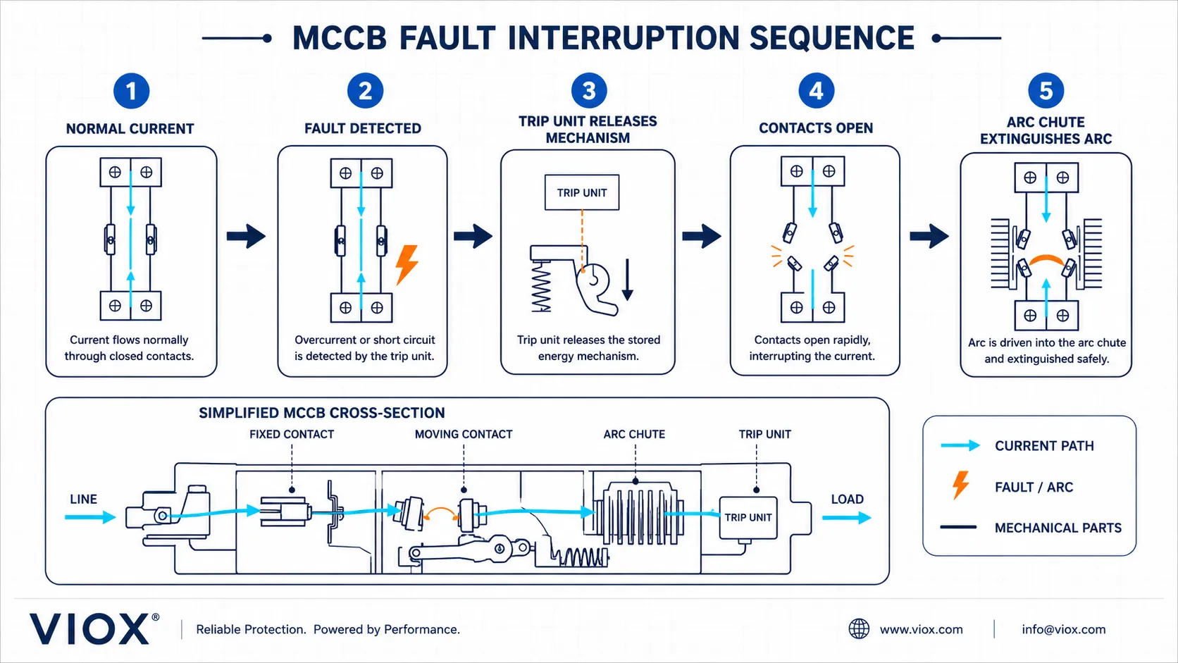
단락 발생 시 시퀀스는 다음과 같습니다:
- 고장 전류가 급격히 상승합니다.
- 트립 유닛이 비정상적인 전류를 감지합니다.
- 트립 유닛이 조작 기구를 해제합니다.
- 조작 기구가 가동 접점과 고정 접점을 분리합니다.
- 접점 사이에 아크가 발생합니다.
- 아크가 아크 슈트 내부로 유도됩니다.
- 아크 슈트가 아크를 분할하고 냉각합니다.
- 차단기의 정격 용량 내에서 전류가 차단됩니다.
- 핸들이 트립 상태를 표시합니다.
- 고장이 해결된 후에만 차단기를 점검하고 재설정합니다.
이 순서는 트립 유닛, 메커니즘, 접점 및 아크 슈트를 왜 함께 고려해야 하는지 설명합니다. 고품질 MCCB는 단일 부품으로 정의되지 않으며, 정격 시험 조건 하에서 전체 차단 시스템이 어떻게 작동하는지에 따라 정의됩니다.
MCCB 내부 부품 vs MCB 내부 부품
MCCB와 MCB는 기능적 개념은 유사하지만 부하 수준이 다릅니다.
| 부품 또는 기능 | MCB | MCCB |
|---|---|---|
| 주택 | 소형 모듈식 본체 | 더 큰 몰드 케이스 |
| 연락처 | 더 작은 최종 회로 부하 | 더 높은 전류를 위한 더 큰 접점 시스템 |
| 트립 장치 | 일반적으로 고정된 열-자기 특성 | 열-자기식 또는 전자식, 종종 더 많은 조정 가능 |
| 아크 슈트 | 더 작은 아크 소호실 | 더 큰 아크 차단 구조 |
| 액세서리 | 모델에 따라 제한적 | 더 폭넓은 액세서리 옵션 |
| 응용 프로그램 | 최종 회로 | 피더, 산업용 패널, 모터, 배전 |
일반적인 제품군 비교는 VIOX를 참조하십시오 MCCB 대 MCB 가이드.
표준 MCCB에는 무엇이 포함되어 있습니까?
표준 배선용 차단기(MCCB)는 일반적으로 다음을 포함합니다:
- 몰드 절연 하우징
- 조작 핸들
- 개폐 기구
- 고정 접점
- 가동 접점
- 아크 슈트
- 열동-전자식 또는 전자식 트립 장치
- 라인 및 부하 단자
- 트립 표시 메커니즘
- 옵션 액세서리 슬롯 또는 구획
정확한 레이아웃은 제조사, 프레임 크기, 트립 유닛 및 액세서리 구성에 따라 다릅니다. 실제 제품 세부 정보는 항상 제조사의 데이터시트 및 설치 매뉴얼을 참조하십시오.
MCCB 내부 구조 FAQ
MCCB의 주요 부품은 무엇입니까?
주요 부품은 몰드 케이스, 조작 핸들, 조작 메커니즘, 고정 및 가동 접점, 아크 슈트, 트립 유닛, 단자 및 옵션 액세서리입니다.
MCCB 내부에서 가장 중요한 부품은 무엇입니까?
단독으로 작동하는 부품은 없습니다. 트립 유닛이 결함을 감지하고, 메커니즘이 접점을 개방하며, 아크 슈트가 아크를 소멸시킵니다. 이 세 가지 모두 결함 차단 시 매우 중요합니다.
MCCB의 아크 슈트란 무엇입니까?
아크 슈트는 부하 또는 단락 전류 상태에서 접점이 열릴 때 발생하는 아크를 분할, 냉각 및 소멸시키는 내부 구조물입니다.
MCCB의 트립 유닛이란 무엇입니까?
트립 유닛은 과부하 또는 단락 전류를 감지하여 조작 메커니즘을 해제합니다. 열동-전자식 또는 전자식일 수 있습니다.
열동-전자식 MCCB와 전자식 MCCB 부품의 차이점은 무엇입니까?
열동-전자식 MCCB는 바이메탈과 전자석 요소를 사용합니다. 전자식 MCCB는 센서와 전자 회로를 사용하며, 종종 더 많은 조정 가능한 보호 기능을 제공합니다.
배선용 차단기(MCCB) 도면은 무엇을 보여줍니까?
유용한 다이어그램은 단자, 접점, 조작 기구, 트립 장치, 아크 슈트, 몰드 케이스 및 액세서리와 함께 전류 경로 및 고장 차단 시퀀스를 보여줍니다.
MCCB 내부 부품을 수리할 수 있습니까?
대부분의 일반적인 현장 적용 환경에서 MCCB 내부 부품은 사용자가 수리하지 않습니다. MCCB가 손상되거나 과열되었거나, 기계적으로 마모되었거나, 심각한 고장을 차단한 경우 제조업체의 지침을 따르고 필요 시 장치를 교체하십시오.
결론
MCCB의 내부 구조는 왜 이 장치가 더 높은 부하의 저압 회로를 보호할 수 있는지 설명해 줍니다. 몰드 케이스는 장치를 지지하고 절연합니다. 접점은 전류를 통전하고 차단합니다. 트립 장치는 과부하 및 단락을 감지합니다. 조작 기구는 접점을 개방합니다. 아크 슈트는 고장 아크를 소호합니다. 액세서리는 제어 및 모니터링 기능을 추가합니다.
기본 의미와 적용에 대해서는 다음부터 시작하십시오. MCCB란 무엇인가요?. 제품 선택에 대해서는 다음으로 계속하십시오. MCCB 선택 가이드 그리고 MCCB 제품 페이지.
