ブログ

ブログのカテゴリー

ATS-switching-time-comparison-timeline-showing-8ms-20ms-50ms-and-06s-transfer-speeds-with-STS-UPS-supported-transfer-fast-ATS-and-motor-operated-ATS-architectures

ATS切替時間の解説:8ms、20ms、50ms、0.6秒の転送速度

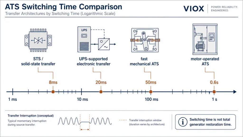
How Fast Does an Automatic Transfer Switch Actually Switch? ATS switching time is the transition interval during which the load is transferred from one power source to another. In practical systems, it can range from sub-cycle transfer in static transfer switch (STS) architectures to hundreds of milliseconds in conventional mechanical automatic transfer switches. This device-level switching time is not the same as total restoration time, which may include source detection, generator start-up, warm-up, transfer delay, and retransfer logic. When engineers compare 8ms, 20ms, 50ms, or 0.6s transfer-speed claims, they are not always comparing the same type of device. An 8ms transfer usually points to solid-state or UPS-supported switching. A 0.6s […]

ATS切替時間の解説:8ms、20ms、50ms、0.6秒の転送速度 続きを読む »

Why 10kA MCBs Are Hard to Mass-Produce: Type Testing, Arc Extinction, and Rating Verification

10kA配線用遮断器(MCB)の大量生産が困難な理由:型式試験、消弧、および定格検証

A 10kA MCB is a miniature circuit breaker rated to interrupt a prospective short-circuit current of 10 kiloamperes under specified test conditions. On a product label, 10kA looks like one simple number. In manufacturing, it is not simple at all. Compared with a 6kA MCB, a 10kA MCB must manage higher arc energy, stronger electrodynamic forces, greater contact stress, higher gas pressure inside the arc chamber, and more severe housing and insulation stress during interruption. Passing a type test with carefully prepared samples is one challenge. Producing thousands or millions of units with the same interruption margin is a different challenge. This article explains why real 10kA MCBs are harder

10kA配線用遮断器(MCB)の大量生産が困難な理由:型式試験、消弧、および定格検証 続きを読む »

1000V DC MCB Design Challenges: Arc Extinction, Multi-Pole Series Breaking, and Rating Verification

1000V DC MCBの設計課題:アーク消弧、多極直列遮断、および定格検証

High-voltage DC miniature circuit breakers look simple from the outside, but a real 800V or 1000V DC MCB is not just an AC breaker with a new label. The core challenge is that DC current has no natural zero-crossing. Once a DC arc forms between opening contacts, it can continue burning unless the breaker forces the current to zero through arc voltage, magnetic blowout, arc splitting, insulation recovery, and synchronized contact opening. That is why reliable 1000V DC MCBs are difficult to design and why the rating printed on the housing is not enough. Buyers and panel builders must verify the actual DC breaking rating, pole wiring method, polarity requirement,

1000V DC MCBの設計課題:アーク消弧、多極直列遮断、および定格検証 続きを読む »

kWh vs MWh vs MW in Battery Energy Storage: C-Rate, P-Rate, SOC, SOH, and DOD Explained

バッテリーエネルギー貯蔵におけるkWh、MWh、MW:Cレート、Pレート、SOC、SOH、DODの解説

If you are new to battery energy storage, the units can feel like alphabet soup: kWh, MWh, MW, C-rate, P-rate, SOC, SOH, DOD, Ah, Wh, and battery notations such as 1P416S. They are related, but they do not measure the same thing. The short answer is simple: kWh, MWh, and GWh measure energy: how much electricity a battery can store or deliver. kW, MW, and GW measure power: how fast that energy can be charged or discharged. C-rate measures current relative to battery capacity. P-rate measures power relative to stored energy. SOC, SOH, and DOD describe battery operating state, ageing, and used capacity. For the narrower difference between power and

バッテリーエネルギー貯蔵におけるkWh、MWh、MW:Cレート、Pレート、SOC、SOH、DODの解説 続きを読む »

TN vs TT vs IT Earthing Systems

TN、TT、IT接地システム:各国における低圧ネットワークの接地方式の違い

Earthing systems define how a low-voltage electrical network connects its power source, exposed metal parts, protective conductors, and the physical earth. The three main IEC earthing arrangements are TN, TT, and IT. They all aim to reduce electric shock and fire risk, but they do it in different ways. The short answer: TN systems use a protective conductor connected back to the supply source. Earth-fault current usually returns through a metallic path, so fault current is relatively high. TT systems use a local earth electrode at the installation. Earth-fault current returns through the soil, so fault current is often lower and residual current devices (RCDs) become essential. IT systems isolate

TN、TT、IT接地システム:各国における低圧ネットワークの接地方式の違い 続きを読む »

VIOX SPD

BESS用サージ保護:DC、AC、および信号用SPD選定ガイド

Quick Answer Surge protection for a battery energy storage system (BESS) should cover three layers: the DC side between battery cabinets and the power conversion system, the AC side connected to the grid or load distribution, and the communication/signal lines used by the battery management system, SCADA, Ethernet, RS485, and auxiliary controls. A BESS is not protected by installing one SPD at one panel. It needs a coordinated protection architecture: DC SPDs at battery and inverter interfaces, AC SPDs at grid and distribution points, and signal SPDs wherever control or communication cables enter or leave cabinets. Why BESS Surge Protection Is Different Battery energy storage systems combine high DC voltage,

BESS用サージ保護:DC、AC、および信号用SPD選定ガイド 続きを読む »

直流コンタクタに特殊な消弧機能が必要な理由:ゼロクロス、磁気吹き消し、および選定ミス

The Core Problem: DC Current Has No Natural Zero Crossing DC contactors need special arc-extinction design because DC current has no natural zero crossing. In an alternating current (AC) circuit, the current naturally passes through zero twice per cycle: 100 times per second at 50 Hz or 120 times per second at 60 Hz. That zero-current moment helps an AC arc collapse. Comparison of AC natural zero-crossing arc extinction versus DC arc behavior, highlighting why DC requires forced extinction mechanisms. In a direct current (DC) circuit, current flows in one direction continuously. When the contactor opens under load, the arc between the contacts does not get a natural zero-current window.

直流コンタクタに特殊な消弧機能が必要な理由:ゼロクロス、磁気吹き消し、および選定ミス 続きを読む »

Technical cutaway diagram of an electrical enclosure showing a removable mounting plate, DIN rails, wire ducts, and control components

電気エンクロージャー用取付プレートガイド:種類、材質、および選定のヒント

Direct Answer An electrical enclosure mounting plate is the removable or fixed internal panel used to support electrical components inside an enclosure. It is also called a back panel, subpanel, mounting board, or mounting backplate depending on the market and enclosure style. Technical cutaway view of an electrical enclosure, illustrating a fully populated removable mounting plate with DIN rails, wire ducts, and control components. Its job is simple but important: it gives circuit breakers, contactors, terminal blocks, power supplies, programmable logic controllers (PLCs), relays, busbars, and wiring accessories a stable mechanical base without drilling every device directly into the enclosure wall. For most control panels and distribution boxes, choose the

電気エンクロージャー用取付プレートガイド:種類、材質、および選定のヒント 続きを読む »

Old UK fuse box with rewireable fuses and no visible RCD protection showing signs that a consumer unit may need upgrading

古い住宅用分電盤の交換が必要かを見極める方法

You open the cupboard under the stairs and find a fuse box that still uses fuse wire. Or maybe it has miniature circuit breakers, but no RCD test button anywhere. The lights work. The sockets work. Nothing smells burnt. So is it actually dangerous, or is someone simply trying to sell you a new consumer unit? This guide is written for UK domestic installations, especially homes in England and Wales where BS 7671, Part P notification, EICR practice, RCD/RCBO protection, and consumer-unit terminology apply. If you are working in a market that uses load centres, panelboards, NEC rules, or NEMA equipment language, the same safety principles may be relevant, but

古い住宅用分電盤の交換が必要かを見極める方法 続きを読む »

Technician-using-infrared-thermography-to-identify-a-localized-overheating-terminal-block-inside-a-control-panel

制御盤における端子台の過熱:原因、診断、および予防

The control panel is still running, no breaker has tripped, and the machine operator has reported only an occasional fault. Then the cabinet door opens: there is a faint burnt smell, one terminal housing has started to discolor, and the thermal camera shows a bright hotspot in an otherwise normal terminal row. Technician using infrared thermography to identify a localized overheating terminal block inside a control panel. This is how many terminal-block failures begin. The connection may continue carrying current for weeks or months while heat slowly damages the conductor, insulation, and surrounding components. By the time the panel stops working, the original cause can be hidden beneath melted plastic

制御盤における端子台の過熱:原因、診断、および予防 続きを読む »

今すぐ見積もりを依頼する