In questa pagina
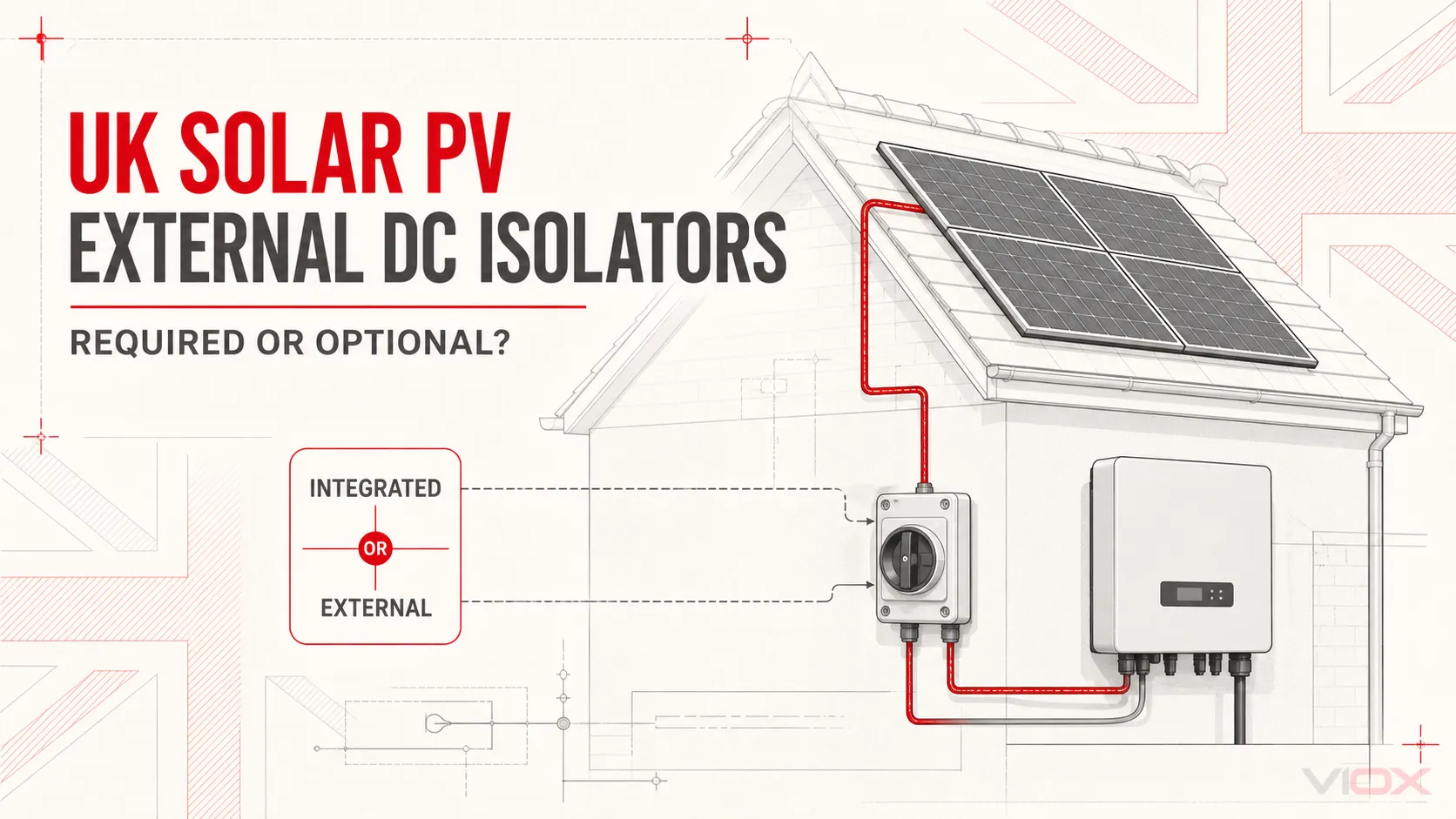
Un impianto fotovoltaico (FV) nel Regno Unito necessita di un mezzo idoneo per isolare l'inverter sia dalle alimentazioni in corrente alternata (AC) che in corrente continua (DC) per una manutenzione in sicurezza. Tuttavia, ciò non non significa che ogni sistema richieda automaticamente un sezionatore DC esterno separato accanto all'inverter.
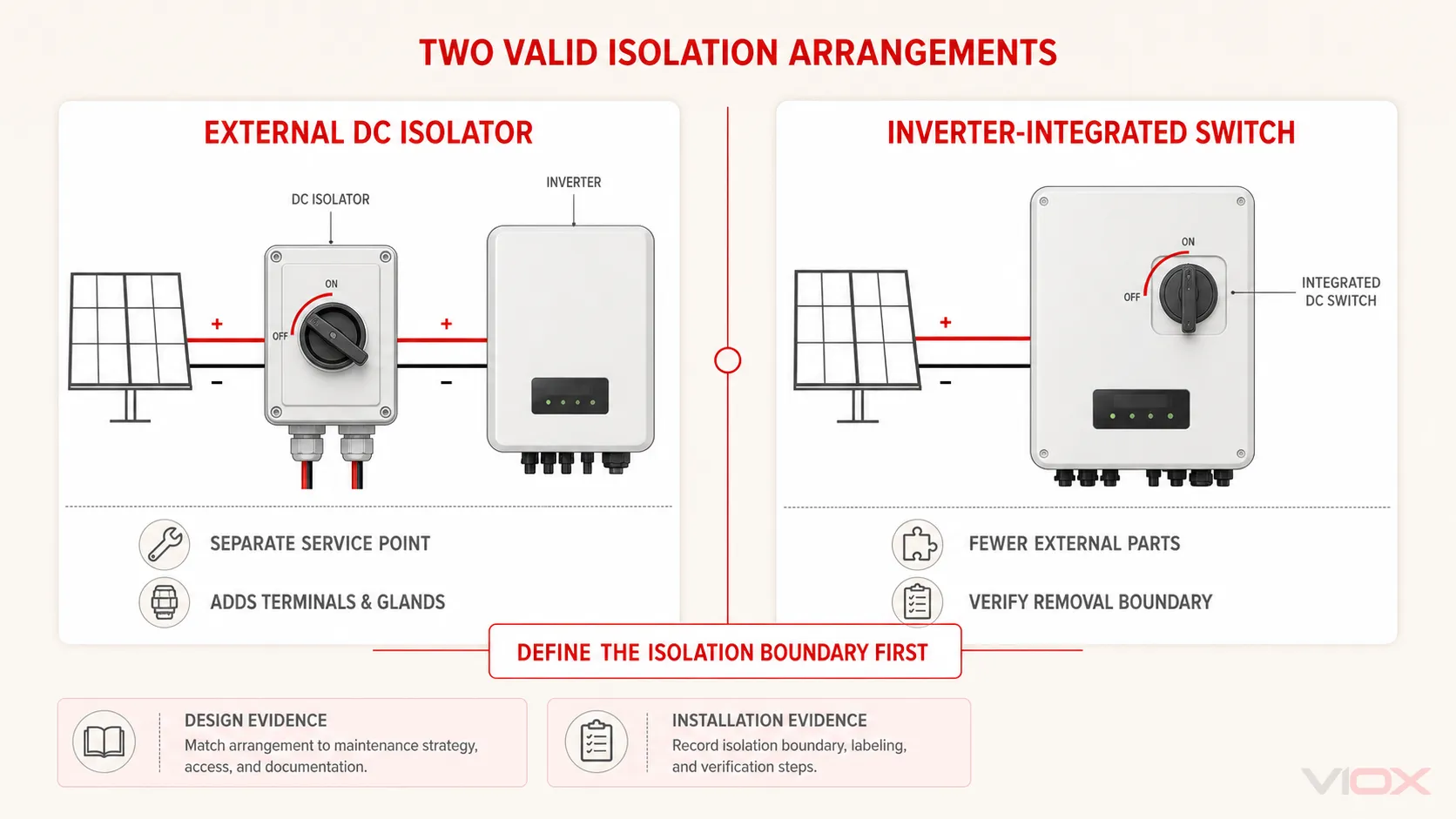
La configurazione corretta dipende dai dispositivi di commutazione integrati nell'inverter, dal limite di isolamento necessario per la manutenzione, dalla configurazione dell'array fotovoltaico, dalle istruzioni dell'apparecchiatura e dai requisiti applicabili al progetto. Un interruttore-sezionatore per impianti fotovoltaici esterno è una soluzione. In alcuni progetti, un dispositivo integrato o un interruttore automatico confermato come idoneo all'isolamento può svolgere la funzione richiesta.
L'importante questione tecnica non è quindi semplicemente: “Un sezionatore esterno è comune?”. È invece:
Quale dispositivo e quale posizione forniscono la funzione di isolamento richiesta senza introdurre un punto di guasto non correttamente dimensionato, installato male o non necessario?
Punti di forza
- I sistemi fotovoltaici nel Regno Unito necessitano di una strategia di isolamento appropriata sul lato DC, ma un involucro esterno separato non è un requisito universale per ogni installazione.
- È possibile fare affidamento sull'interruttore DC integrato di un inverter solo quando la sua funzione, i valori nominali, l'accessibilità, il limite di isolamento e le istruzioni del produttore soddisfano i requisiti del progetto.
- Laddove sia richiesto l'isolamento sotto carico, utilizzare un dispositivo idoneo per l'inserzione, l'interruzione e l'isolamento alla tensione e alla corrente DC fotovoltaiche calcolate.
- Ai sensi della norma BS EN IEC 60947-3, la categoria DC-PV0 non è una categoria di commutazione sotto carico. Le categorie DC-PV1 e DC-PV2 coprono diverse condizioni dei circuiti fotovoltaici.
- Un sezionatore esterno aggiunge contatti, morsetti, ingressi cavi e un involucro. Una specifica o un'installazione inadeguate possono renderlo un pericolo anziché un miglioramento della sicurezza.
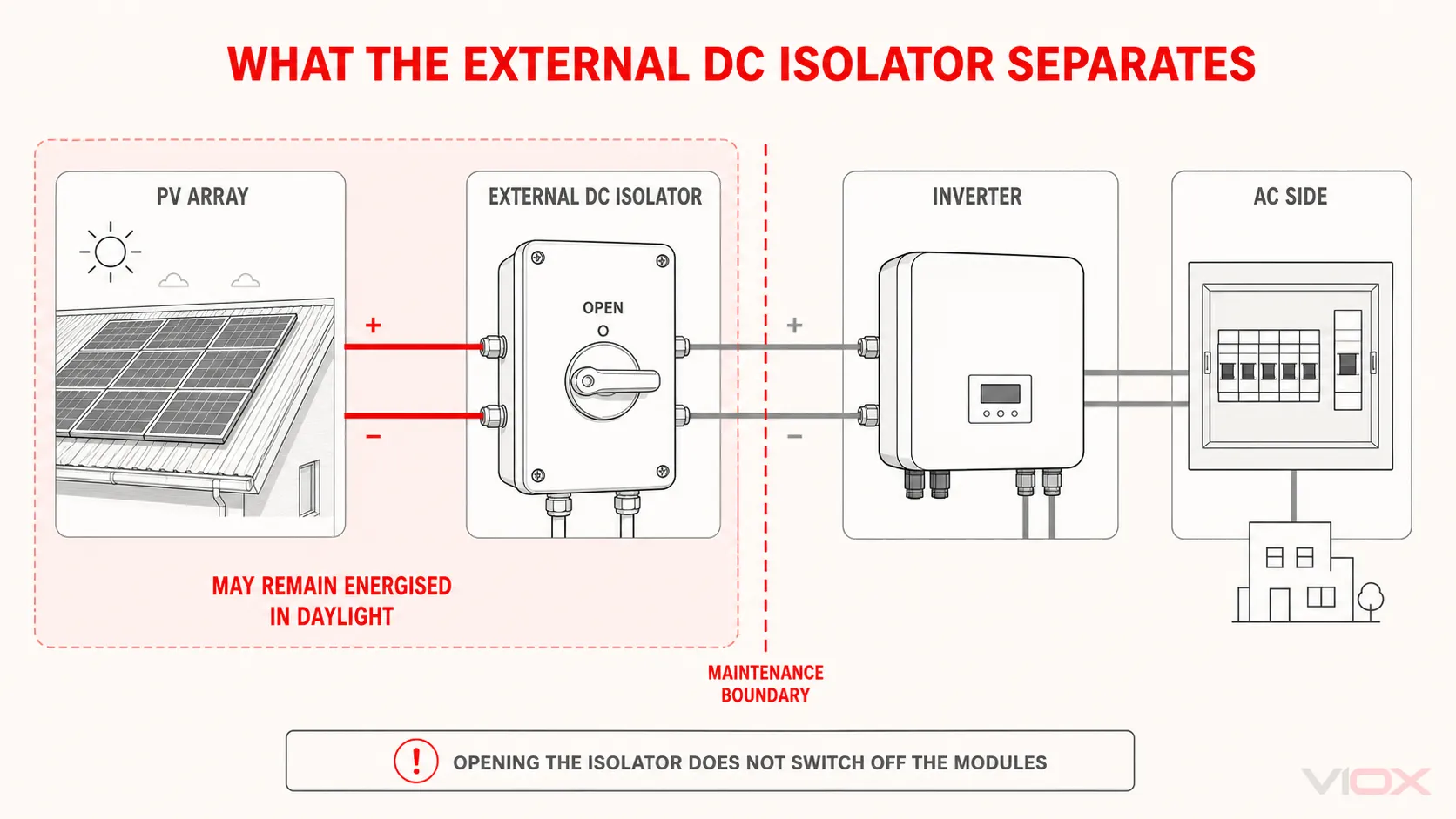
- L'apertura di un sezionatore CC non interrompe la generazione di tensione da parte dei moduli. I conduttori tra l'impianto e il punto di sezionamento aperto possono rimanere sotto tensione durante le ore diurne.
Quando è opportuno utilizzare un sezionatore CC esterno?
La seguente tabella è uno strumento di screening progettuale e non sostituisce l'edizione vigente della norma BS 7671, il Codice di Pratica IET, le istruzioni del produttore o una valutazione del rischio specifica per il progetto.
| Condizione del sistema | Un sezionatore CC esterno separato è probabilmente utile? | Cosa deve essere verificato? |
|---|---|---|
| L'inverter è dotato di un interruttore CC integrato e accessibile e la relativa documentazione conferma il servizio di isolamento e commutazione richiesto. | Potrebbe non essere necessario se duplica semplicemente una funzione già prevista | Funzione del dispositivo, valori nominali in CC, limite di manutenzione sicura, accessibilità, dispositivi di blocco dove richiesti e istruzioni dell'inverter |
| L'inverter deve essere rimosso mentre il cavo FV rimane collegato all'impianto dell'edificio | Spesso utile perché può creare un punto di isolamento di servizio indipendente dall'inverter | Quali conduttori rimangono sotto tensione, accessibilità dei morsetti, posizione, capacità di interruzione del carico e procedura di isolamento sicuro |
| Diverse stringhe sono collegate in parallelo | Spesso appropriato all'uscita combinata o al limite dell'apparecchiatura pertinente | Corrente di progetto combinata, possibile corrente inversa, categoria di utilizzo CC-FV, configurazione dei poli e strategia di protezione contro le sovracorrenti |
| Una string box richiede un sezionatore principale locale | Comunemente appropriato come interruttore-sezionatore integrato o adiacente | Corrente combinata, tensione massima, condizioni dell'involucro e distinzione tra isolamento e protezione da sovracorrente |
| Un interruttore automatico CC idoneo è già previsto | Un sezionatore separato potrebbe non essere necessario se solo per duplicazione | L'interruttore deve essere esplicitamente idoneo per la funzione di isolamento e manovra richiesta, non solo per la protezione da sovracorrente CC |
| Il sezionatore proposto sarebbe esposto su un tetto o su una parete esterna | Solo quando il vantaggio dell'isolamento giustifica i rischi ambientali e di connessione aggiuntivi | Controllo delle infiltrazioni d'acqua, esposizione ai raggi UV e alla temperatura, ingresso dei cavi, integrità dell'involucro, accesso e manutenzione |
| Il progetto esistente o i documenti contrattuali specificano un punto di isolamento esterno | Solitamente richiesto a meno che il progetto non venga formalmente revisionato | Specifica applicabile, approvazione del progettista, requisiti del produttore, registri di ispezione e documentazione di consegna |
Questo quadro spiega perché gli isolatori esterni sono comuni negli impianti britannici, senza considerare la prassi comune come una regola legale universale.
Perché gli isolatori CC sono diventati comuni nel fotovoltaico nel Regno Unito
1. L'inverter necessita di un confine pratico per la manutenzione
I moduli solari producono tensione CC ogni volta che è presente luce sufficiente. Spegnere l'alimentazione CA dell'edificio non elimina la fonte fotovoltaica. Un tecnico che effettua la manutenzione di un inverter necessita quindi di un metodo definito per separarlo dai conduttori CC lato campo.
Un sezionatore esterno vicino all'inverter fornisce un punto di manovra locale visibile. Può inoltre rimanere collegato al cablaggio fisso quando l'inverter viene rimosso. Questa pratica funzione di servizio è uno dei motivi per cui i dispositivi esterni sono diventati una parte comune degli impianti fotovoltaici nel Regno Unito.
2. L'isolamento esterno è facile da identificare e documentare
Un involucro dedicato può rendere chiaro il punto di isolamento a installatori, ispettori e personale di manutenzione. L'attuale modello di messa in servizio MIS 3002 registra la corrente nominale, la tensione nominale, l'ubicazione e il controllo funzionale del sezionatore dell'array. Ciò dimostra l'importanza di documentare il sistema di isolamento, sebbene il modello stesso non debba essere interpretato come prova che ogni progetto richieda un involucro esterno separato.
3. I design delle apparecchiature più vecchie e miste non forniscono tutti la stessa funzione integrata
Gli inverter moderni includono comunemente un interruttore CC, ma le funzioni del prodotto e i limiti di manutenzione differiscono. Alcuni interruttori integrati possono isolare i circuiti interni dell'inverter lasciando sotto tensione determinati terminali o cavi collegati. Altri potrebbero non fornire le caratteristiche di manovra, blocco o accessibilità necessarie per una specifica procedura.
Il manuale del prodotto e la progettazione del sistema, non la sola presenza di una manopola rotativa, devono stabilire cosa isola effettivamente l'interruttore.
4. I sistemi a stringhe multiple necessitano di un'architettura di commutazione deliberata
Le stringhe fotovoltaiche in parallelo modificano la corrente e le possibili condizioni di flusso di corrente nel circuito combinato. Un sezionatore all'uscita della scatola di giunzione o all'ingresso dell'inverter può fornire un pratico punto di disconnessione comune. Il dispositivo deve tuttavia essere scelto in base alle condizioni del circuito combinato; installare un involucro familiare senza verificarne la capacità di interruzione dipendente dalla tensione non è adeguato.
È richiesto un sezionatore CC esterno dalla norma BS 7671?
Evitare di ridurre questa domanda a una risposta di una sola parola.
La guida IET stabilisce che gli inverter richiedono un mezzo di sezionamento sia dal lato CA che da quello CC per la manutenzione. Quando il progettista sceglie uno o più sezionatori CC esterni, tali dispositivi devono essere correttamente dimensionati per lo specifico impianto fotovoltaico. La stessa guida osserva che un interruttore automatico idoneo al sezionamento può essere utilizzato anche ai sensi della norma 712.537.2.2.102 della BS 7671.
Ciò crea un'importante distinzione:
| Livello di requisito | Significato ingegneristico |
|---|---|
| Funzione richiesta | Il progetto deve fornire le necessarie funzioni di sezionamento e commutazione per l'apparecchiatura e le operazioni di manutenzione. |
| Dispositivo possibile | Un sezionatore CC fotovoltaico esterno con taratura corretta può fornire tale funzione. |
| Possibile alternativa | Un interruttore integrato o un interruttore automatico idoneo possono essere accettabili quando le loro capacità documentate e la disposizione dell'installazione soddisfano il requisito. |
| Non stabilito dall'aspetto | Una maniglia rotativa, una marcatura “ON/OFF” o un valore di corrente elevato non dimostrano di per sé l'idoneità al sezionamento o all'interruzione del carico alla tensione CC del sistema. |
Per i lavori MCS, la norma MIS 3002:2025 Issue 2.0 richiede che i sistemi siano progettati e installati in conformità con la seconda edizione del Codice di Pratica IET per i sistemi fotovoltaici solari collegati alla rete, fatte salve le aggiunte e le eccezioni dichiarate dalla norma stessa. Specifica inoltre che l'ultima versione della BS 7671 ha la precedenza in caso di conflitto tra i requisiti.
Poiché gli standard e le istruzioni dei prodotti cambiano, il progettista o l'installatore deve verificare le edizioni applicabili alla data del progetto invece di copiare una disposizione da un'installazione precedente.
Sezionatore esterno vs Interruttore CC integrato nell'inverter
Nessuna delle due configurazioni è automaticamente superiore. Il confronto riguarda la funzionalità, l'accessibilità e i punti di guasto aggiuntivi.
| Fattore decisionale | Sezionatore CC fotovoltaico esterno | Interruttore CC integrato nell'inverter |
|---|---|---|
| Separazione di servizio durante la sostituzione dell'inverter | Può rimanere con il cablaggio fisso e fornire un confine separato | Può rimanere meccanicamente parte dell'inverter; verificare come viene eseguita la rimozione |
| Identificazione visiva | Spesso chiara e etichettata localmente | Dipende dal design e dall'etichettatura dell'inverter |
| Terminali CC e ingressi cavi aggiuntivi | Sì | Solitamente meno componenti esterni |
| Esposizione a pioggia, raggi UV, calore e condensa | Dipende fortemente dalla posizione e dall'installazione dell'involucro | Dipende dalla posizione e dalla costruzione dell'inverter |
| Verifica specifica del modello | Obbligatorio | Obbligatorio |
| Rischio di duplicazione non necessaria | Possibile | Non applicabile quando è il mezzo di sezionamento selezionato |
Un dispositivo esterno è giustificato quando fornisce un reale vantaggio in termini di manutenzione o controllo del sistema. Aggiungerne uno solo perché “i sistemi nel Regno Unito ne hanno sempre uno” non è una logica di progettazione sufficiente.
Come specificare un sezionatore CC fotovoltaico esterno
Se il progetto richiede un dispositivo esterno, la specifica dovrebbe partire dal circuito, non dalla corrente nominale di catalogo.
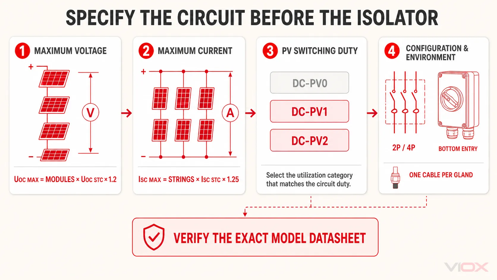
1. Calcolare la tensione fotovoltaica massima
La tensione a circuito aperto del fotovoltaico aumenta in condizioni di freddo. La guida alla selezione IET corrente presenta il seguente percorso di progettazione:
UOC MAX = numero di moduli in serie × UOC STC × 1,2La guida osserva inoltre che un metodo alternativo può utilizzare la temperatura più bassa del sito e il coefficiente di temperatura della tensione del modulo. Il metodo richiesto per il progetto deve essere applicato in modo coerente, utilizzando dati del modulo verificati.
L'isolatore selezionato deve quindi essere verificato alla tensione calcolata. La corrente di interruzione ammissibile di un dispositivo può diminuire all'aumentare della tensione CC.
2. Calcolare la corrente massima del circuito
Per le stringhe in parallelo, la stessa guida IET presenta:
ISC MAX = numero di stringhe in parallelo × ISC STC × 1,25Il dispositivo di manovra all'uscita combinata deve essere selezionato in base alla corrente di progetto combinata. La necessità di una protezione da sovracorrente per le stringhe è una decisione separata; un sezionatore manuale non sostituisce fusibili o interruttori automatici.
3. Selezionare la categoria di utilizzo FV corretta
La norma BS EN IEC 60947-3 include categorie specifiche per il fotovoltaico:
| Categoria di utilizzo | Servizio tipico | Limitazione principale |
|---|---|---|
| DC-PV0 | Sezionamento in assenza di corrente | Non classificato per l'apertura o la chiusura sotto carico; non idoneo laddove l'isolamento dell'inverter richieda l'interruzione sotto carico |
| DC-PV1 | Stringa FV singola o circuiti in cui non possono verificarsi sovracorrenti significative | Verificare che il circuito effettivo soddisfi questa condizione |
| DC-PV2 | Circuiti FV in cui possono verificarsi sovracorrenti significative e la corrente può fluire in entrambe le direzioni, come nel caso di stringhe in parallelo sullo stesso inverter | Spesso pertinente a circuiti combinati o a stringhe in parallelo |
Non dedurre la categoria di utilizzo da una fotografia del prodotto o da un'etichetta generica di “sezionatore solare”. Ottenere la scheda tecnica esatta e la documentazione di conformità per il modello citato.
4. Verificare la configurazione dei poli e il cablaggio
Gli interruttori-sezionatori bipolari e quadripolari possono avere capacità di tensione e corrente in corrente continua (DC) differenti. È possibile collegare più contatti in serie per estendere il percorso efficace dell'arco; altre configurazioni possono utilizzare collegamenti in serie e in parallelo. La disposizione consentita è specifica per ogni prodotto.
Verificare:
- l'esatta configurazione dei terminali e dei collegamenti;
- se il design è sensibile alla polarità;
- la tensione/corrente nominale in DC per quella configurazione;
- i collegamenti forniti dal produttore e lo schema di installazione;
- i requisiti di disconnessione simultanea dei conduttori; e
- l'idoneità per le operazioni di chiusura, apertura e isolamento previste.
Non dare mai per scontato che un collegamento diretto o uno schema di cablaggio utilizzato su un altro modello sia valido.
5. Corrispondenza con l'ambiente di installazione
Per un'unità esterna, il grado di protezione IP dichiarato è solo il punto di partenza. Le prestazioni dell'involucro possono essere compromesse da un ingresso dei cavi o da un montaggio inadeguati.
La norma MIS 3002 suggerisce che, per mantenere il grado di protezione IP appropriato in ambienti esterni, potrebbe essere necessario l'ingresso dei cavi dal basso, l'uso di un anello di gocciolamento (drip loop) e un solo cavo per pressacavo. L'IET sottolinea inoltre l'importanza del riscaldamento solare e dell'esposizione ai raggi UV, specialmente su pareti esposte a sud, nonché la necessità di preservare l'integrità dell'involucro durante il fissaggio dell'unità.
Verificare quanto segue in conformità con le istruzioni di installazione e del produttore:
- esposizione ad acqua, condensa, polvere, raggi UV e temperatura ambiente;
- direzione di ingresso dei cavi e idoneità dei pressacavi;
- un solo cavo di dimensioni corrette per ogni pressacavo;
- punti di fissaggio che non compromettano la tenuta dell'involucro;
- idoneità del morsetto per la classe del conduttore;
- eventuale trattamento richiesto con puntalini o guaine; e
- coppia di serraggio specifica per il modello e requisiti di ispezione.
Perché un sezionatore aggiuntivo può aumentare il rischio
Un sezionatore non diventa più sicuro solo perché è esterno o etichettato per uso solare. Esso aggiunge un involucro, contatti di commutazione, terminazioni, pressacavi e lavoro di installazione, tutti elementi che devono rimanere affidabili nell'ambiente di utilizzo reale.
L'indagine del BRE del governo britannico sugli incendi che hanno coinvolto sistemi fotovoltaici ha identificato tre problemi ricorrenti nei sezionatori CC: scarsa progettazione o costruzione del prodotto, dispositivi sottodimensionati rispetto alla tensione o alla corrente fotovoltaica collegata e installazione inadeguata. Negli incidenti esaminati in quella parte del rapporto, nove sezionatori installati in modo errato sono stati associati a incendi o eventi termici. Quattro incidenti hanno coinvolto l'ingresso di acqua nei sezionatori CC attraverso pressacavi rivolti verso l'alto.
Questi risultati non significano che i sezionatori esterni non debbano mai essere utilizzati. Significano che il vantaggio dell'isolamento deve essere accompagnato da una corretta selezione del prodotto, configurazione, lavorazione dell'involucro, ispezione e manutenzione. La panoramica del governo rileva inoltre che l'incidenza di incendi legati al fotovoltaico è stata complessivamente molto bassa, quindi le prove dovrebbero supportare una migliore ingegneria piuttosto che affermazioni allarmistiche.
Una lista di controllo per l'approvvigionamento e la verifica della progettazione
Prima di approvare un sezionatore CC esterno per un progetto fotovoltaico nel Regno Unito, richiedere e verificare:
- il produttore esatto e il numero di modello;
- i calcoli della tensione e della corrente di progetto fotovoltaico massima;
- la portata nominale del dispositivo a quella tensione CC, non solo la sua corrente nominale di targa;
- la documentazione di conformità all'edizione applicabile della norma BS EN IEC 60947-3;
- la categoria di utilizzo DC-PV0, DC-PV1 o DC-PV2 come richiesto dal circuito;
- le marcature e le funzioni di chiusura, apertura e sezionamento;
- la configurazione bipolare o quadripolare e lo schema elettrico approvato;
- limitazioni di polarità e direzione della corrente;
- classe dei conduttori dei terminali e requisiti di preparazione;
- gradi di protezione dell'involucro e ambientali appropriati per il luogo di installazione;
- coppia di serraggio del produttore e istruzioni di installazione;
- requisiti di blocco e indicazione di posizione per la procedura di manutenzione;
- interazione con l'interruttore integrato dell'inverter;
- l'esatto limite di isolamento mostrato nello schema unifilare; e
- registri di ispezione, messa in servizio e consegna.
Se è necessaria anche una funzione di protezione da sovracorrente, esaminare i ruoli distinti in Sezionatore CC vs Interruttore automatico CC nelle scatole di combinazione solari. Per una spiegazione più ampia del dispositivo stesso, vedere Cos'è un sezionatore solare CC?.
La conclusione
I sezionatori CC esterni sono comuni negli impianti fotovoltaici nel Regno Unito perché possono fornire un confine di manutenzione chiaro e accessibile tra il cablaggio dell'impianto fotovoltaico e l'inverter. Tuttavia, la pratica comune non equivale a un requisito universale.
La progettazione deve innanzitutto definire la funzione e il confine di isolamento. Deve quindi determinare se tale funzione sia fornita al meglio da un interruttore integrato nell'inverter, da un interruttore automatico idoneo o da un sezionatore CC fotovoltaico esterno. Se viene selezionata un'unità esterna, la sua categoria di utilizzo fotovoltaico, la capacità di interruzione dipendente dalla tensione, la corrente nominale, la configurazione dei poli, l'ambiente di installazione e la documentazione del modello devono corrispondere al circuito reale.
Per i progetti che richiedono un dispositivo separato, esaminare la Gamma di sezionatori fotovoltaici CC VIOX e richiedere la scheda tecnica del modello esatto e i documenti di conformità prima della specifica. La collocazione di una famiglia di prodotti su un sito web non costituisce prova che un particolare modello soddisfi i requisiti britannici di un progetto.
Domande Frequenti
È legalmente richiesto un sezionatore CC esterno per ogni impianto fotovoltaico nel Regno Unito?
Non considerarlo un requisito universale. L'installazione necessita dei mezzi di sezionamento e commutazione richiesti, ma l'implementazione accettabile dipende dall'apparecchiatura, dalla progettazione del sistema, dalla versione applicabile della norma BS 7671, dalla guida IET e dai requisiti del progetto. Un involucro esterno separato è una possibile implementazione, non l'unica.
L'interruttore CC integrato nell'inverter può sostituire un sezionatore esterno?
Può farlo quando la documentazione del produttore conferma le funzioni di commutazione e sezionamento richieste, le caratteristiche nominali, l'accessibilità e il limite di manutenzione. Verificare cosa rimane sotto tensione quando l'interruttore è aperto e come l'inverter può essere rimosso in sicurezza.
È possibile utilizzare un interruttore automatico CC al posto di un sezionatore CC?
Potenzialmente. La guida IET osserva che un interruttore automatico idoneo al sezionamento può essere utilizzato secondo le disposizioni pertinenti della norma BS 7671. La sua capacità di interruzione in CC e l'idoneità al sezionamento devono essere esplicitamente stabilite; un interruttore non è automaticamente un sezionatore solo perché dispone di una posizione OFF.
È possibile utilizzare un sezionatore CA sul lato CC del fotovoltaico?
Solo se il dispositivo specifico possiede una classificazione CC documentata ed è idoneo per le operazioni di chiusura, apertura e sezionamento in CC richieste alla tensione e alla corrente di sistema calcolate. Una classificazione CA da sola non è trasferibile al servizio fotovoltaico in CC, poiché gli archi in CC sostenuti sono più difficili da estinguere.
Un sezionatore CC sul tetto è più sicuro di un sezionatore lato inverter?
Non necessariamente. Le posizioni sul tetto o esposte possono aumentare i rischi legati all'acqua, ai raggi UV, alla temperatura, all'accesso e alla manutenzione. Posizionare il punto di sezionamento in base al confine di isolamento richiesto e a una valutazione progettuale documentata, non basandosi sul presupposto generale che più sezionatori significhino sempre maggiore sicurezza.
L'apertura del sezionatore CC rende sicuro ogni cavo fotovoltaico?
No. I moduli solari possono continuare a generare tensione durante le ore diurne. L'apertura di un sezionatore interrompe il circuito in quel punto, ma i conduttori tra i moduli e il dispositivo aperto possono rimanere sotto tensione. Un lavoro sicuro richiede una procedura di isolamento e verifica approvata, eseguita da personale competente.