

On this page
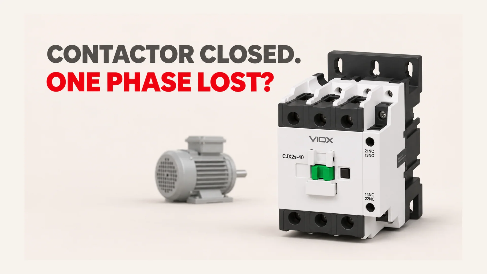
Yes. A three-pole contactor can pull in while one main pole fails to conduct, leaving a three-phase motor with an open supply line. A burnt or loose contact can also remain conductive but develop excessive resistance, causing voltage unbalance under load before it fails completely. Hearing the contactor click, seeing its indicator move, or receiving ordinary auxiliary-contact feedback does not prove that all three power paths are healthy.
If the motor hums without accelerating, loses torque, develops unusual heat, or repeatedly trips its overload, stop it. Do not keep restarting it to see whether the problem clears.
This guide concerns line-fed, low-voltage three-phase induction motors. Variable-frequency drive outputs, star-delta starters, and reversing arrangements require their own circuit-specific diagnosis.
Key Takeaways
- Separate a fully open pole from a high-resistance pole: both can harm a motor, but they produce different evidence.
- Locate the fault through the supply, contactor, overload, cable, and motor path. A motor symptom alone does not identify the failed component.
- A continuity beep or a voltage reading on the motor side is insufficient proof of healthy load conduction.
- An upstream voltage monitor may see a healthy supply while a contactor pole downstream has failed.
- Repair the cause and verify motor condition and protection before returning the starter to service.
How One Contactor Pole Creates the Problem
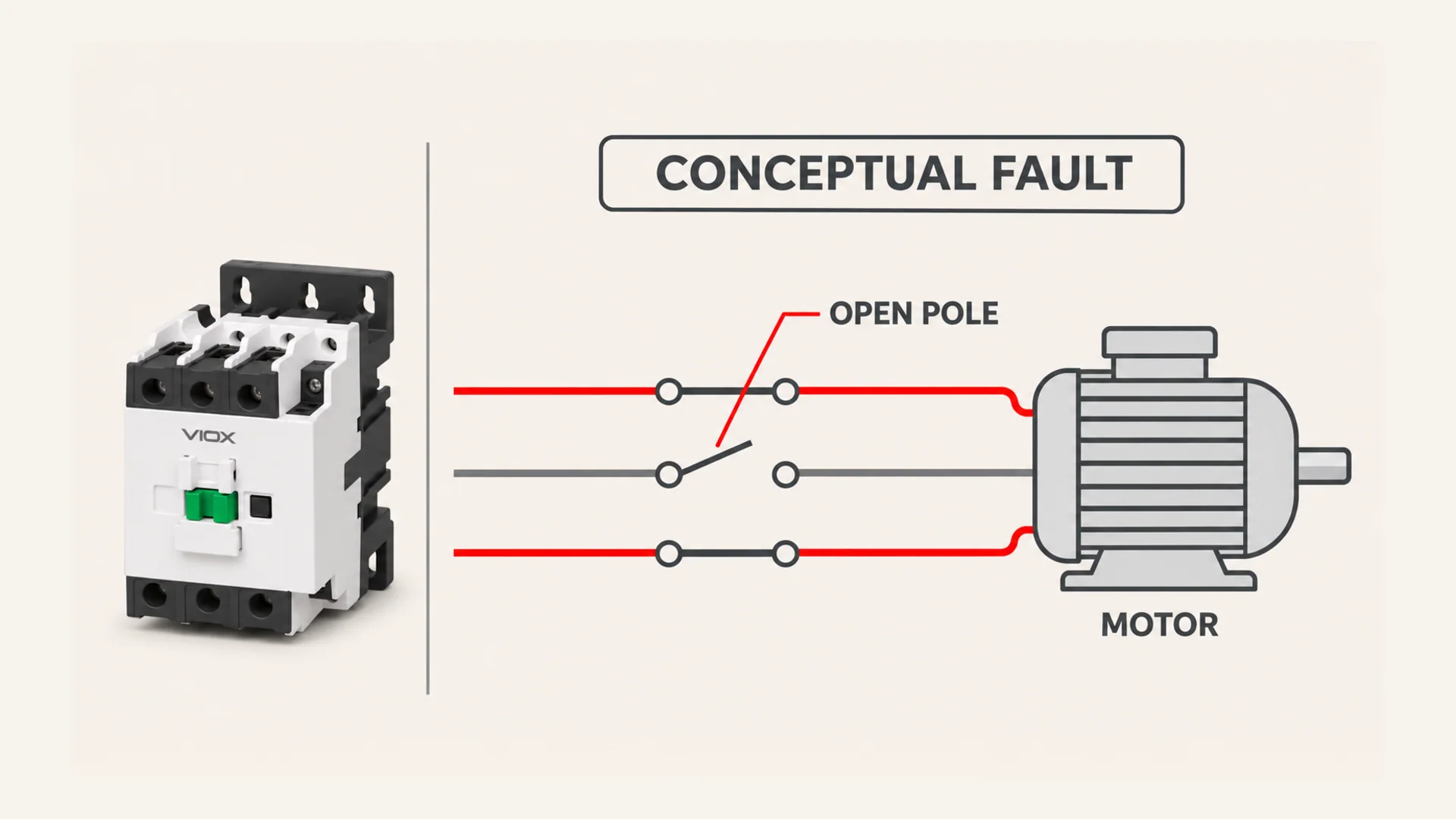
In a normal three-pole starter, the coil moves a common mechanism, but each main pole still has its own contact interfaces and terminations. One can deteriorate while the others remain usable.
| Condition | Electrical consequence | Diagnostic meaning |
|---|---|---|
| One pole has excessive contact or termination resistance | Local heating and a load-dependent voltage drop; motor-terminal voltages can become unbalanced | A resistive phase path, not necessarily a complete open phase |
| One pole does not make contact, or a connection in that pole is open | One motor supply line is interrupted | A possible source of single-phasing, even though the mechanism pulled in |
| The coil drops out or the mechanism never closes | Normally all main poles open | A control or actuator problem; not automatically a single failed pole |
Burning can be a consequence as well as a cause. A loose termination, inadequate contact pressure, unsuitable switching duty, persistent chatter, or a previous fault can damage a pole. Conversely, discoloration alone does not establish that the contact has failed. The U.S. Department of Energy lists loose, pitted, worn, or poorly adjusted controller contacts among poor connections associated with heating in its motor selection and application guide.
Do not confuse a power-pole fault with a burnt coil. The coil operates the mechanism; the main contacts carry motor current. A healthy coil can operate a contactor whose power path is defective.
Why the Motor May Keep Turning
A rotating induction motor may continue running after a supply phase is lost, depending on its load and operating condition. Continued motion therefore does not prove a healthy three-phase supply. The Louisiana Transportation Research Center describes this condition as single-phasing in its motor-protection training material.
The two remaining supply lines provide a single-phase source across them. This is not a healthy “two-phase” operating mode for the original three-phase motor.
At standstill, an ordinary three-phase induction motor supplied through only two lines generally cannot self-start without another starting or phase-conversion arrangement. It may hum or stall instead. Michigan State University’s phase-converter note explains that starting boundary.
Unequal currents and abnormal magnetic conditions can increase losses and heat. Even before a complete open circuit develops, a resistive connection can create harmful unbalance: DOE explains that small voltage differences can cause much larger current differences, torque pulsations, and overheating in its voltage-unbalance tip sheet.
There is no universal “burns out in 60 seconds” rule. Damage depends on load, cooling, motor construction, fault severity, prior temperature, and protective response. The correct response is to stop and diagnose, not to estimate how long it can keep running.
Diagnose the Phase Path, Not Just the Contactor
Before physical inspection or resistance testing, isolate all relevant power and control sources, apply the site’s lockout procedure, and verify absence of voltage. Account for backfeeds and stored energy. Switching the coil off is not isolation. In U.S. workplaces, OSHA 1910.333 addresses these practices; use applicable local rules elsewhere.
The table below is an interpretation framework for qualified electrical personnel. It does not instruct an operator to run a damaged motor for a live test. Use existing event records and de-energized checks first. Any necessary energized measurement needs a justified, controlled procedure, suitable instruments, and protective measures.
| Evidence pattern | What it suggests | Next action |
|---|---|---|
| Supply abnormal before the contactor | Upstream fuse, breaker pole, connection, feeder, or supply fault | Localize upstream; do not replace the contactor solely from the motor symptom |
| Incoming supply acceptable, but one isolated contactor pole fails the permitted state/continuity check | Open or mechanically unreliable main-contact path | Confirm the fault is within the contactor; replace or use an approved service part |
| A particular pole or terminal has abnormal heat and a disproportionate drop under previously recorded or safely authorized load conditions | Resistive contact, termination, or conductor interface | Separate the terminal from the internal contact path; inspect the full heat-affected connection |
| Contactor paths are satisfactory, but the affected phase is interrupted farther downstream | Overload power path, cable, terminal, or motor fault | Continue localization toward the motor rather than condemning the contactor |
| One motor line current is absent or strongly reduced | An open or severely impaired phase path is possible | Establish where the interruption occurs; current alone does not identify the component |
| All phase currents disappear as the armature releases | Control dropout or a protective stop | Follow the control-circuit diagnosis, not a single-pole assumption |
Divide the circuit into three sections
Supply section: Establish whether the incoming supply was healthy at the time of the symptom. Identify whether the evidence was recorded before or after protective devices, since a failed fuse or connection can otherwise be missed.
Contactor section: Assess each complete pole path and its terminations using the exact device’s permitted test method. If a fault is attributed to a main contact, distinguish it from a loose lug or heat-damaged conductor beside it. A voltage-drop measurement across a pole is a different measurement from a phase-to-phase voltage comparison; record which was used.
Downstream section: Check the overload power path, connections, motor cable, and motor. Normal voltage at the contactor output does not establish continuity through every component after it. Isolated motor continuity tests can locate some defects; insulation and winding-condition assessment may require a motor specialist.
For the general coil and contact test sequence, use the VIOX contactor multimeter testing guide. If the mechanism repeatedly drops out, use the buzzing and chattering diagnostic guide instead of treating every event as a burnt pole.
Three Readings That Can Mislead You
“The auxiliary contact says it is on”
An ordinary auxiliary contact reports its own mechanical state. It does not measure the conductivity of each main pole. A control system can receive an on signal while a damaged power contact remains open or resistive. Special monitored contact arrangements also have defined limits; do not infer a three-pole conduction test from their name.
“The meter beeps across the contact”
A handheld meter tests with a small current. A conductive path at that current does not prove acceptable operation at motor load. Ordinary meters may not resolve small resistance changes, and connected windings or parallel paths can distort readings. Use manufacturer criteria and appropriate equipment; do not invent a universal milliohm replacement limit.
“There is voltage on all three motor terminals”
A running motor can produce a voltage on an interrupted phase through electromagnetic coupling. Connected circuits can also create misleading readings. A voltage indication therefore does not prove that the missing supply path can deliver load current. Equally, absence of useful current does not prove that a conductor is safe to touch. Interpret voltage and current together with circuit state and isolated path tests.
Why a Phase Monitor May Miss a Failed Pole
A voltage relay can only evaluate the electrical quantities connected to its sensing inputs. If it monitors the incoming supply before the contactor, a failed contactor pole is outside that measured boundary. The relay can correctly report healthy input voltage while the motor has an interrupted line downstream.
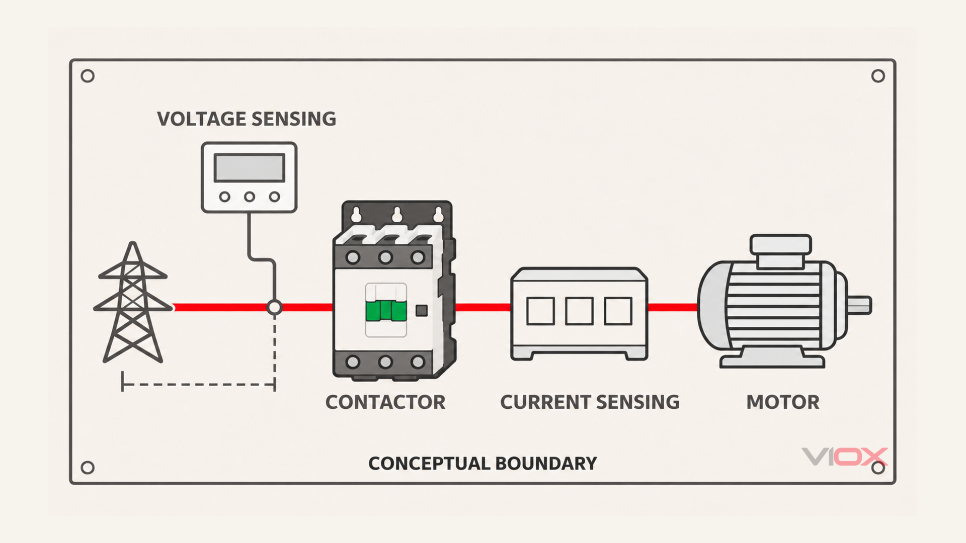
Do not solve this by casually moving voltage-monitor wires to the motor side. Off-state voltage, start permissives, relay supply, induced voltage, and restart logic all affect that design. Use an engineered arrangement suited to the relay and starter.
| Protective function | What must be verified for this fault |
|---|---|
| Upstream voltage/phase monitor | Sensing location and whether the failed contact lies within its observed circuit |
| Thermal overload relay | Explicit phase-failure sensitivity, settings, trip behavior, and suitability for the motor duty |
| Electronic overload or motor relay | Which current-loss, current-unbalance, or negative-sequence functions are actually included and enabled |
| Breaker or fuse | Appropriate short-circuit and overcurrent coordination; not assumed to provide dedicated phase-loss diagnosis |
| Embedded motor temperature protection | Sensor position and trip chain; it supplements other functions rather than repairing the open phase |
Current-based protection can observe an abnormal motor-current condition that an upstream voltage-only monitor cannot. Its coverage still depends on sensor location, pickup levels, delays, and the actual relay algorithm. No device name guarantees that a particular motor will be protected under every load condition. See the VIOX low-voltage motor protection guide for the broader function boundaries.
Repair the Cause and Verify Before Restart
Replace a contactor with unreliable main contacts, heat-damaged insulation, or mechanical damage unless its manufacturer provides an appropriate service procedure and approved parts. Do not bridge the failed pole, hold the mechanism closed, file contacts without authorization, or enlarge protection settings to keep the motor running.
An approved replacement still needs the correct load-duty rating, operating voltage, coil supply, auxiliary arrangement, mounting, and coordinated protection. IEC 60947-4-1 addresses contactors and motor-starters; its official scope is not proof that any two devices with similar current markings are interchangeable. The VIOX AC contactor range provides series options; confirm the exact model and coil code for the application.
Before a controlled return to service, the responsible technician should document:
- Fault location: Which pole, termination, or downstream component failed, and what evidence identified it?
- Root cause: Were load duty, control chatter, connection quality, environmental conditions, or a previous fault involved?
- Affected equipment: Are conductors, lugs, overload components, cable, and the motor fit for service after the heat exposure?
- Protective coverage: Will the installed sensing and trip chain respond to the relevant phase-loss condition, without defeating start or safety logic?
- Restoration evidence: After repairs and the required pre-start checks, does a controlled commissioning run show acceptable three-phase voltage, current, acceleration, and thermal behavior against the equipment criteria?
If the repair is complete but the motor still has abnormal current, heat, noise, or acceleration, stop and investigate further. Replacing a visibly burnt contactor does not prove that the motor escaped damage or that the original cause was removed.
Sources
- U.S. DOE: Premium Efficiency Motor Selection and Application Guide
- U.S. DOE: Eliminate Voltage Unbalance
- Louisiana Transportation Research Center: Electrical Safety and Protection, Chapter 6
- Michigan State University: Electrical Tech Note 322, Phase Converters
- OSHA: 29 CFR 1910.333
- IEC 60947-4-1:2023, corrected version 2026-03