

On this page
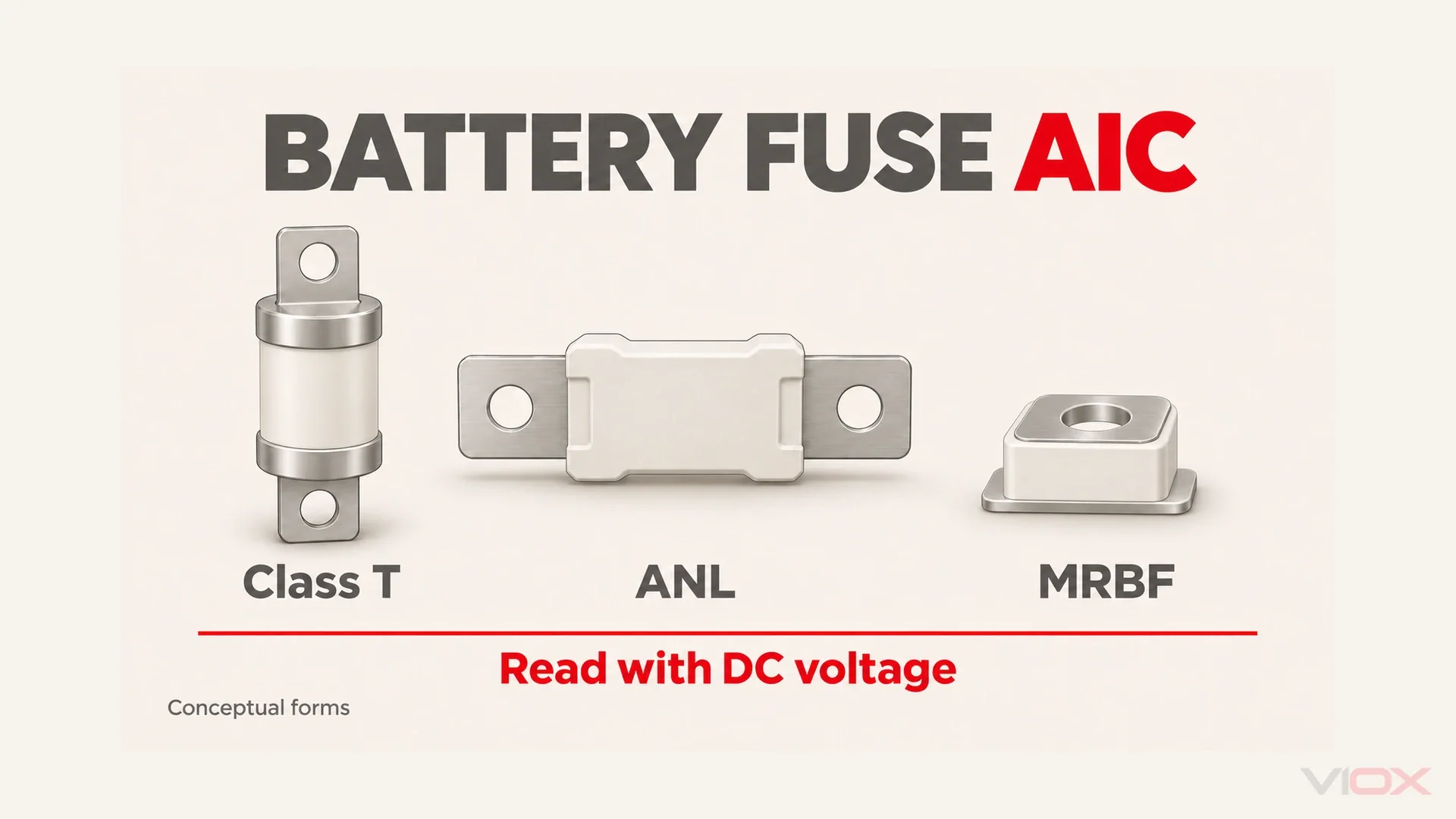
For a lithium battery main fuse, check ampere interrupting capacity (AIC) at the applicable DC voltage before choosing the fuse’s ampere rating. Matching the operating current does not establish that the fuse can safely clear a battery short circuit.
| Form: Blue Sea example | Published DC interrupt capacity | Selection boundary |
|---|---|---|
| Class T: 5120 | 20,000A @ 125V DC | Higher interruption capability; verify complete application |
| ANL: 5136 | 6,000A @ 80V DC | Reject when required fault duty exceeds this value |
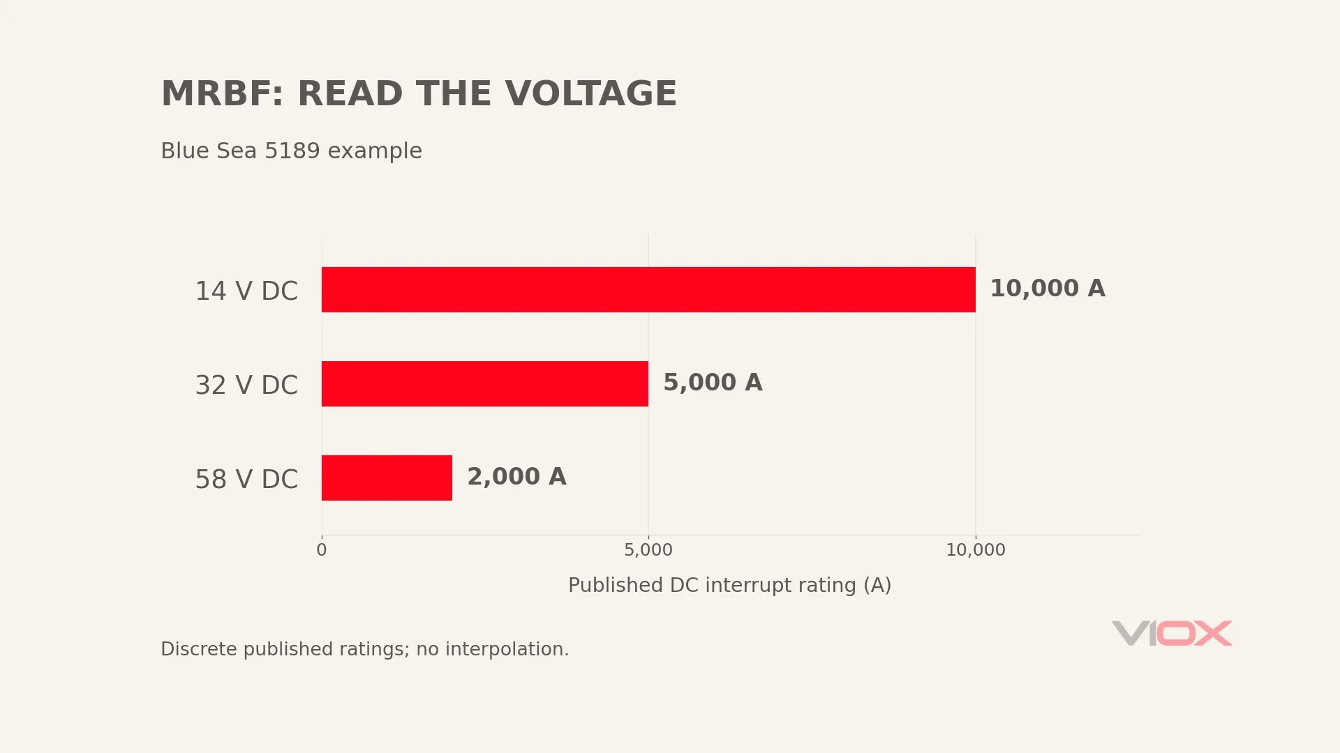
| MRBF: 5189 | 10,000A @ 14V; 5,000A @ 32V; 2,000A @ 58V DC | Use the applicable voltage entry |
These manufacturer examples, documented in Sources, are not universal ratings for every similarly shaped fuse. AIC is the first screening gate here; voltage, operating current, clearing behavior and holder suitability still matter.
1. Why Lithium Changed the Fuse Question
A fuse’s ampere rating describes its current-carrying and operating characteristics under specified conditions. Its interrupt rating addresses a different event: whether it can stop the prospective fault current at the stated voltage. Neither value substitutes for the other.
Lithium iron phosphate (LiFePO4) battery systems can deliver severe short-circuit current because the source and connecting path may have very low resistance. A protection arrangement carried over from a lead-acid installation therefore needs a new fault-duty assessment. This does not mean every lithium battery produces the same fault current, or that every lead-acid bank has a mild fault duty.
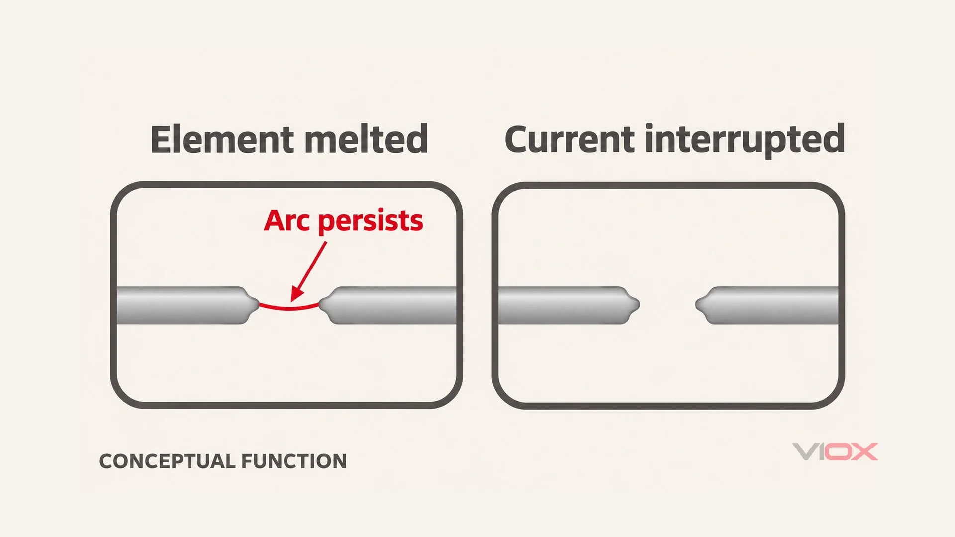
If the duty exceeds the fuse’s interrupt capability, the element may melt without safely clearing the circuit. An arc can continue across the opened element; conductive damage or enclosure rupture may follow. A blown-looking fuse is not proof that the fault was successfully interrupted. Do not expect a battery management system (BMS) operating-current specification to establish the external fuse’s interrupt duty.
For an off-grid, RV, marine or residential storage project, record the actual source configuration. Chemistry, capacity and nominal voltage identify the starting point; manufacturer fault-current evidence and the applicable installation rules govern the design. The battery energy storage systems guide covers the surrounding system rather than this fuse-form decision.
2. How Much AIC Do You Actually Need?
Start With the Battery Manufacturer’s Short-Circuit Data
Request the battery or assembled bank’s short-circuit current (SCC), the conditions behind it, and the source configuration to which it applies. A maximum continuous discharge current, a short-duration output limit and a BMS trip threshold are different specifications. Do not copy one into the SCC field because it is the largest current printed on the datasheet.
Check whether the document describes an individual battery or the assembled bank. Parallel sources and other connected sources can change the duty at the main fuse. Series-connected capacity must not be added as though the batteries were in parallel. If the configuration is not covered by the supplied data, ask for a bank-level assessment rather than inventing a multiplier.
The decision compares the documented fault duty at the proposed device location with an applicable DC interrupt rating. It does not involve deliberately shorting a battery, nor measuring its fault current with an ordinary clamp meter. Keep fault-current assessment and live-system work with a qualified designer or installer.
Ask the supplier to identify the document revision and explain whether the value includes any internal protective device. If interruption depends on an internal device operating, obtain the applicable evidence for that arrangement instead of assuming every BMS will limit a fault in the same way. If the supplier cannot establish what the number represents, record SCC as unresolved. An unexplained number is not a sound basis for declaring one of the three fuse forms suitable.
When SCC Is Unknown: A Bounded ABYC Estimation Route
ABYC E-11-2025 is a marine electrical standard. Its clause 11.10.1.3.2.2 provides a chemistry-based calculation route when battery SCC is unknown: for lithium-ion batteries, use 5kA per 100Ah. The associated lead-acid fallback uses 3kA per 100Ah, with thin-plate pure lead treated with lithium-ion instead. Flooded-battery provisions have their own scope; do not apply that lead-acid figure indiscriminately.
This article uses the lithium route as an explicit screening assumption:
Estimated fault-current requirement = 5kA × bank capacity in Ah / 100Ah.
It is not a measurement, a universal relationship between capacity and internal resistance, or a global rule for stationary storage and RV installations. E-11 also has other provisions and alternatives. These two examples do not reproduce the complete standard or authorize unrestricted extrapolation to larger banks. Confirm the governing installation rules and exact source arrangement before accepting the requirement.
Example A: A Nominal 48V, 200Ah LiFePO4 Bank
Assume SCC is unavailable, the stated capacity describes the bank, and the marine fallback route is applicable. For the shared comparison, assume the verified maximum system voltage does not exceed 58V DC. If it exceeds that limit, the MRBF example already fails the voltage check.
5kA × 200Ah / 100Ah = 10kA estimated requirement.
Using the published examples in the opening table:
- MRBF’s 2,000A @ 58V DC entry is below 10kA: it fails this interruption screen. Its 10,000A @ 14V entry cannot be imported into a higher-voltage installation.
- ANL’s 6,000A @ 80V DC entry is also below 10kA: this named example fails the same screen.
- Class T’s 20,000A @ 125V DC entry exceeds 10kA: it passes the interruption comparison, subject to the voltage assumption and exact product applicability.
That last result does not choose the fuse’s ampere rating or approve the installation. The conductor, load, clearing characteristic, holder and installation conditions remain separate checks. If maximum system voltage is unknown, the final result remains incomplete even when the current comparison looks favorable.
Example B: A Nominal 12V, 100Ah LiFePO4 Bank
Under the same stated fallback assumptions:
5kA × 100Ah / 100Ah = 5kA estimated requirement.
An MRBF entry of 10,000A @ 14V DC exceeds this current requirement. It is a valid candidate only if the maximum operating and charging voltage, and the manufacturer’s application conditions, permit using that entry. “12V nominal” alone does not prove this.
If the system exceeds that voltage point, do not interpolate a new AIC. Check a manufacturer-supported higher-voltage entry. The published 5,000A @ 32V DC entry equals the estimated requirement; where the actual voltage and instructions permit it, the numerical interruption comparison passes at equality. Equality does not establish spare capacity or resolve uncertainty in the source assessment. Class T and the named ANL example also exceed the estimated current requirement at their respective stated voltages, subject to their application conditions.
3. The Three Forms, One by One
Class T: A Strong Candidate for Higher Fault Duty
The Blue Sea 5120 example publishes 20,000A @ 125V DC and identifies UL 248-15 Class T listing. Class T’s current-limiting behavior is a useful characteristic, but it must not become an assumed fixed ceiling on every fault. The exact fuse’s operating data and applicable fault conditions determine its behavior.
Use a holder specifically intended for the selected fuse and current range. For example, the manufacturer’s linked block range of 225-400A is a compatibility range, not a recommendation to fit that ampere rating to every lithium bank. The actual protection setting still follows the circuit and equipment requirements.
Keep different manufacturers’ data separate. Eaton’s JJN documentation is useful evidence for Class T construction and current-limiting characteristics; it does not turn Blue Sea’s voltage-tagged specification into a universal Class T number. Read the exact part’s DC entry. An AC interrupt rating cannot fill an absent DC field.
Class T is therefore a strong candidate in the larger worked example, not an automatic requirement established merely by the word “lithium.” Nor does the format guarantee adequacy if a verified fault duty exceeds the chosen part’s published capability.
ANL: Evaluate Its Published Limit, Not Its Reputation
ANL appears in many existing low-voltage battery and inverter installations. A familiar bolted format and a matching ampere rating can make it an attractive replacement, but neither establishes interruption adequacy after changing the battery bank.
Blue Sea 5136 currently publishes 6,000A @ 80V DC. Use that exact model-and-voltage statement rather than an undated reseller description or a universal ANL value. It is lower than the Class T example, but the comparison is not a tenfold difference and the devices have different declared voltage points.
For the 200Ah fallback example, that ANL value is insufficient. For a smaller or manufacturer-documented source duty within its declared capability, ANL is not categorically excluded by the chemistry name. The complete application still needs verification. Conversely, an oversized ANL ampere rating cannot compensate for an insufficient interrupt rating.
MRBF: Convenient Packaging With a Voltage-Dependent Limit
Marine Rated Battery Fuses (MRBF) offer a compact terminal-block arrangement. Use the compatible fuse block and assembly instructions; terminal mounting does not mean the bare fuse can be attached in any improvised arrangement.
The verified Blue Sea 5189 specification is:
| Stated DC voltage | Published interrupt capacity |
|---|---|
| 14V DC | 10,000A |
| 32V DC | 5,000A |
| 58V DC | 2,000A |
The same form can consequently be a candidate in the smaller worked screen and fail the larger, higher-voltage screen. That is the useful distinction. Calling MRBF universally unsuitable for lithium would hide the smaller-system case; calling it a “10kA fuse” without the voltage would hide the failure case.
Choose its convenience only after the electrical checks pass. Neither a compact mounting position nor an impressive current rating proves that the assembled connection and fault duty are acceptable.
4. The Voltage Trap
Interrupt capacity is tied to a stated test voltage and conditions. DC current does not have the recurring natural current zeros of an AC waveform. As the supply voltage rises, sustaining an arc across an opened path becomes a more demanding interruption problem. The fuse must achieve complete clearing, not simply create a melted gap.
That explains why a manufacturer’s published AIC can decrease at higher DC voltages. It does not provide a formula for deriving unlisted values. Use the declared entries and application instructions; do not draw a line between the MRBF ratings and calculate a supposed intermediate approval.
The voltage used for selection must also represent the system’s maximum relevant duty, including charging conditions, rather than its convenient nominal name. The 12V example needs this check before claiming the 14V entry. The 48V example likewise needs confirmation against the selected device’s voltage rating.
A seller’s short description saying only “10,000A AIC” is incomplete evidence, not proof that the underlying product is counterfeit. Request the model-specific voltage pairing. Also distinguish a fuse-link rating from a holder or complete-assembly rating: the documents must cover the parts actually installed.
Record the current and voltage together in the specification. Writing the pair prevents a future replacement from retaining the ampere value while silently substituting a different voltage-duty capability.
5. Decision Table: Which Form Passes the AIC Screen?
This table uses only the two stated capacity estimates and the published examples. “Pass” means the interruption comparison is satisfied under the listed conditions. It does not approve the fuse’s operating-current selection, complete assembly or installation.
| Nominal bank and assumption | Estimated requirement | Class T example | ANL example | MRBF example |
|---|---|---|---|---|
| 12V, 100Ah; fallback applicable; maximum voltage verified | 5kA | Pass at 20kA @ 125V DC, within application limits | Pass at 6kA @ 80V DC, within application limits | Conditional: 10kA @ 14V only if applicable; 5kA @ 32V can meet the estimate where authorized |
| 48V, 200Ah; fallback applicable; maximum voltage verified | 10kA | Pass at 20kA @ 125V DC, within application limits | Fail: 6kA @ 80V DC is insufficient | Fail: applicable 2kA @ 58V DC entry is insufficient |
| Either bank; SCC, maximum voltage or applicable instructions unresolved | Not established | Evidence needed | Evidence needed | Evidence needed |
Before specification, retain a short evidence record: source configuration, SCC document or stated estimation route, maximum DC voltage, exact fuse identity, applicable interrupt rating, holder identity and the outstanding operating-characteristic checks. A change to the bank or charging arrangement should trigger review of that record.
For an existing installation, compare the fitted part with that record rather than relying on the shape visible through a cover. A physically compatible replacement may have different electrical limits. If a candidate passes the AIC comparison but the holder or clearing data is missing, retain it as a candidate and request the missing evidence; do not upgrade the result to approved. This separates a defensible technical shortlist from an instruction to energize the system.
Position the main protection close to the battery source in accordance with the applicable installation requirements and equipment instructions. This is a qualitative source-protection principle; it is not a complete marine placement rule or a main/branch wiring plan.
VIOX does not sell Class T, ANL or MRBF fuses. Its IEC fuse families must not be called Class T equivalents. For any brand, including candidates in the VIOX fuse range, documented DC interruption capability at the applicable voltage must cover the verified fault duty before further selection can proceed. Missing data leaves suitability unverified: do not specify the product for this battery duty until that evidence is supplied. A gPV fuse is intended for PV string protection; that role does not establish battery main-protection suitability.
6. FAQ
Can I use an ANL fuse on a LiFePO4 battery bank?
Potentially, if the exact fuse’s DC voltage and interrupt capability cover the verified duty and the remaining protection requirements are satisfied. The named 6,000A @ 80V DC example exceeds the smaller 5kA estimate but fails the larger 10kA estimate. Chemistry alone neither approves nor rejects every ANL.
Why does my fuse’s AIC rating change with voltage?
The opened fuse must extinguish the DC arc under its rated conditions. Higher voltage can make that task more demanding, so the manufacturer may publish different interrupt capacities at different voltages. Use the applicable pair; do not interpolate or carry a lower-voltage rating into another system.
Is a DC circuit breaker a substitute for a Class T fuse?
Only after its DC interrupt capability covers the fault duty and its voltage, operating behavior, installation and equipment requirements are verified. Reset capability is not an AIC substitute. The DC circuit breaker guide for solar, battery and EV systems covers that separate selection route.
How do I find my battery bank’s short-circuit current?
First request manufacturer data covering the actual bank and conditions. Do not substitute continuous discharge current or a BMS trip setting. If SCC is unavailable, use an estimation route permitted by the governing design basis; this article illustrates the scoped ABYC lithium fallback, not a universal measurement method.
Does every battery in a parallel bank need its own fuse?
Main protection does not, by itself, establish protection for every battery connection or possible backfeed path. Individual protection depends on the actual arrangement, equipment instructions and applicable installation rules. The main battery fuse and branch interrupt-rating guide explains why one high-AIC main fuse does not automatically validate downstream protection; a qualified designer must determine the bank’s layout.
7. Sources
- Blue Sea Systems 5120 Class T fuse: 20,000A @ 125V DC, listed class and linked compatible block range.
- Blue Sea Systems 5136 ANL fuse: 6,000A @ 80V DC.
- Blue Sea Systems 5189 MRBF terminal fuse: three voltage-tagged interruption ratings.
- ABYC E-11-2025, AC and DC Electrical Systems on Boats: clauses 11.10.1.3.2.1-2 and Table 3C for the bounded marine estimation discussion. Publicly reproduced text excerpts were checked; this guide is not a full-standard compliance review.
- Eaton Bussmann JJN Technical Data 1025, July 2023: Class T family characteristics and current limitation; exact-part ratings remain controlling.