في هذه الصفحة
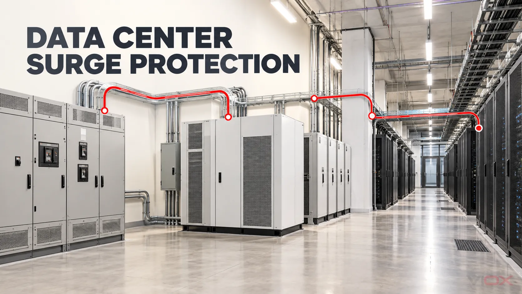
يجب أن يتبع تصميم الحماية من زيادة التيار في مركز البيانات كل مسار موصل، وليس مجرد قائمة منتجات عامة من ثلاثة مستويات. ابدأ بالمخطط أحادي الخط وتتبع مصدر المرافق، ومصدر المولد، ومفتاح التحويل التلقائي (ATS)، ولوحة التوزيع الرئيسية ذات الجهد المنخفض، ومدخل ومسار تجاوز وحدة إمداد الطاقة غير المنقطعة (UPS)، والتوزيع في اتجاه التيار، ووحدة توزيع الطاقة (PDU) أو لوحة الطاقة البعيدة (RPP)، وتغذية الحوامل، وواجهات البيانات أو التحكم النحاسية المكشوفة.
تعامل مع كل انتقال كحد حماية محتمل. قم بتعيين جهاز حماية من زيادة التيار الكهربائي (SPD) فقط بعد التأكد من جهد النظام، وترتيب التأريض، والتعرض المتوقع لزيادة التيار، وهدف تحمل المعدات، وتيار القصر الكهربائي المحتمل، ومسار التوصيل، وأدلة التنسيق. إن وجود UPS أو PDU للحامل أو تصنيف kA عالٍ لا يكمل هذه المراجعة بحد ذاته.
حد التصميم: هذا الدليل عبارة عن سير عمل هندسي مفاهيمي، وليس تعليمات لتوصيل أطراف التوصيل أو اعتماد مشروع. يمكن أن تحتوي أنظمة طاقة مراكز البيانات على مصادر طاقة متعددة، وطاقة مخزنة، ومسارات تجاوز، ومستويات أعطال عالية. يتطلب التصميم النهائي، والتركيب، والاختبار، والصيانة موظفين مؤهلين، والمخطط أحادي الخط المعتمد، وتعليمات المعدات، والكود المعمول به، والدراسات الخاصة بالمشروع.
حدد مسار زيادة التيار الكهربائي الكامل في مركز البيانات
تعتمد توافرية مركز البيانات على بنية الطاقة الكاملة، وليس فقط على مصدر التغذية الرئيسي. قد يمر مسار التشغيل العادي عبر لوحة مفاتيح رئيسية، أو UPS، أو PDU، أو RPP، أو مجرى قضبان التوصيل (busway) قبل الوصول إلى معدات تكنولوجيا المعلومات. أثناء تعطل المصدر أو إجراء أعمال الصيانة، قد تمر الطاقة بدلاً من ذلك عبر مولد، أو مغذٍ بديل، أو مسار تجاوز ثابت (static bypass)، أو مسار تجاوز للصيانة، أو مسار توزيع ثانٍ من النوع A/B.
لذلك يجب أن تمثل مراجعة الاندفاع الكهربائي (surge review) كل حالة يمكن أن تظل فيها المعدات تحت الجهد الكهربائي:
مصدر المرافق ── لوحة مفاتيح LV الرئيسية ── دخل UPS ── خرج UPS ── PDU/RPP ── خزانة A
      │                    │                    ▲
      │                    └── تجاوز UPS ──────┘
      │
مولد ── مفاتيح المولد ── ATS ──────┘

مصدر/مسار بديل ── لوحة مفاتيح B ── UPS B ── توزيع B ── خزانة B

خدمات نحاسية خارجية ── الشبكة / BMS / الحريق / الأمن / ضوابط التبريد ── معدات تكنولوجيا المعلومات
هذه خريطة حدودية وليست طوبولوجيا قياسية. تستخدم بعض المنشآت أنظمة UPS مركزية، بينما يستخدم البعض الآخر بنيات UPS موزعة أو معيارية، وقد تختلف النقطة التي يتم عندها اشتقاق أو تبديل المحايد (neutral). ISO/IEC 22237-3:2021 تضع مصادر الطاقة، والتوزيع الداخلي، وربط الاتصالات، والحماية من الصواعق، وقياس جودة الطاقة ضمن نطاق توزيع الطاقة في مركز البيانات. وجهة النظر النظامية هذه هي السبب في أن دراسة SPD لا يمكن أن تتوقف عند مدخل الخدمة. إن VIOX الأوسع صفحة تطبيقات مراكز البيانات والاتصالات تحدد الحماية من الاندفاع الكهربائي جنباً إلى جنب مع النقل، والمراقبة، وحماية الفرع، والتوزيع دون استبدال مراجعة تصميم SPD هذه.
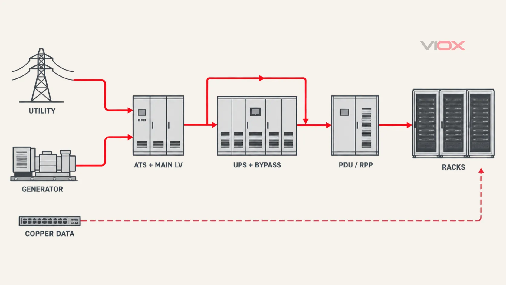
الحدود الثمانية التي يجب تحديدها على المخطط أحادي الخط
| حد فاصل | سؤال المراجعة الأولي | الأدلة مطلوبة قبل الموافقة | إغفال شائع |
|---|---|---|---|
| خدمة المرافق ولوحة التوزيع الرئيسية للجهد المنخفض (LV) | ما هو حمل الاندفاع الخارجي الذي يمكن أن يصل إلى مدخل المنشأة؟ | ترتيب التغذية والتأريض، وسياق الصواعق، والجهد الاسمي والجهد المستمر الأقصى، وفئة/نوع SPD المطبق، ومستوى الحماية، وبيانات تيار القصر وحماية النسخ الاحتياطي | الاختيار بناءً على رقم تيار التفريغ الأكبر فقط |
| مسار المولد ومفتاح التحويل التلقائي (ATS) | هل يمكن للمصدر البديل، أو المغذي المكشوف، أو مخطط التحويل، أو ترتيب الربط أن يخلق تعرضاً منفصلاً؟ | المخطط أحادي الخط للمولد و ATS، ومسار الموصل، وخصائص المصدر، ومعالجة المحايد، وظروف الأعطال، وتعليمات المعدات | حماية دخل الشبكة فقط |
| دخل UPS العادي | ما هي العابرة التي يمكن أن تصل إلى المقوم أو مرحلة الدخل؟ | تحمل دخل UPS والتعليمات، وبيانات SPD المنبع، ومسار الموصل المثبت، وظروف المصدر والأعطال | بافتراض أن ملصق UPS يثبت وجود حماية خارجية كافية |
| مسار التجاوز (bypass) لـ UPS | هل يمكن لمسار التجاوز (bypass) تغذية الحمل متجاوزاً مسار التحويل العادي؟ | طوبولوجيا التجاوز الساكن وتجاوز الصيانة، ومصدر التجاوز، وحالات التبديل، ومتطلبات الشركة المصنعة | مراجعة مسار UPS العادي وليس مسار التجاوز |
| مخرج UPS وتوزيع الطاقة في المراحل اللاحقة | هل هناك حاجة إلى مرحلة SPD إضافية لتحقيق الهدف المطلوب عند طرف توصيل الجهاز؟ | طوبولوجيا المخرج، والعزل الجلفاني أو المحايد المشتق حيثما ينطبق ذلك، ومسافة الكابلات، وقدرة تحمل المعدات اللاحقة، وتوافق الشركة المصنعة | تركيب SPD عند المخرج كإجراء روتيني دون التحقق من سلوك UPS |
| وحدة توزيع الطاقة (PDU)، ولوحة توزيع الطاقة عن بُعد (RPP)، ومسار القضبان النحاسية (busway)، والتوزيع الفرعي | هل يخدم حد التوزيع منطقة حماية متميزة أو مساراً طويلاً في اتجاه التيار؟ | طوبولوجيا المحول أو بدون محول، وتخطيط الفرع، وتيار القصر الكهربائي، وقدرة تحمل المعدات، وأدلة التنسيق | بافتراض أن كل وحدة توزيع طاقة (PDU) تحتوي على حماية مناسبة من الاندفاع الكهربائي |
| تغذيات طاقة الحامل (Rack) | هل يمكن لمرحلة نقطة الاستخدام تحسين هدف طرف توصيل المعدات النهائي دون إنشاء تتابع غير مُتحقق منه؟ | جهد تغذية الحامل، وخصائص وحدة توزيع الطاقة (PDU)، وواجهة المعدات النهائية، وبيانات التنسيق بين المنبع والمصب | التعامل مع شريط الحامل العادي كجهاز حماية من الاندفاع الكهربائي (SPD) من النوع 3 مُتحقق منه |
| بيانات النحاس، والمراقبة، وواجهات التحكم | هل يمكن لتيار الاندفاع الدخول أو الخروج عبر مسار موصل غير مخصص للطاقة؟ | جهد الواجهة، التيار، عرض النطاق الترددي/معدل البيانات، فئة PoE حيثما كان ذلك مناسباً، تخصيص الدبوس/الزوج، التدريع، الربط، الموصل، معيار الاختبار | حماية طاقة AC مع ترك واجهات النحاس المكشوفة دون مراجعة |
جهاز الـ UPS ليس هو مواصفات الحماية من زيادة التيار
يحل جهاز UPS وجهاز SPD مشكلات أساسية مختلفة. يمكن لجهاز UPS توفير طاقة احتياطية أثناء انقطاع التيار وقد يقوم بتنظيم أو تهيئة الطاقة وفقاً لطوبولوجيته. يتم تقييم جهاز SPD لقدرته على تحديد الجهد العابر وتحويل تيار الاندفاع في ظل ظروف اختبار محددة. تحتوي بعض طرازات UPS على مكونات داخلية لتحديد الاندفاع، ولكن وجودها، وأنماط الحماية، وواجب الاختبار، وترتيب فاصل الدائرة، وحدود التنسيق تعتمد على الطراز.
اطلب وثائق UPS الدقيقة بدلاً من الاعتماد على الكلام يو بي إس:
- ما هي أطراف توصيل الدخل، والتجاوز (bypass)، والخرج الموجودة؟
- ما هي المسارات التي تظل متصلة في حالات التشغيل العادي، والبطارية، والتجاوز الساكن (static-bypass)، وتجاوز الصيانة (maintenance-bypass)، وحالات العطل؟
- هل تعلن الشركة المصنعة عن وجود حماية داخلية من الاندفاع، وبموجب أي طريقة اختبار وأنماط؟
- ما هي ترتيبات SPD الخارجية المسموح بها أو المطلوبة؟
- هل يمكن أن يؤثر إضافة SPD على مراقبة التيار المتبقي، أو مراقبة العزل، أو المرشحات، أو توافق المصدر، أو تنسيق الحماية؟
- هل المخرج مشتق بشكل منفصل، أو معزول بمحول، أو بدون محول، أو يتم تبديله بطريقة تغير مرجع التأريض؟
يمكن أن تختلف الإجابة بين أنظمة التحويل المزدوج، والتفاعلية مع الخط، والأنظمة النمطية، والأنظمة القائمة على محولات، والأنظمة بدون محولات. لا تضع SPD على مخرج UPS لمجرد أن المخطط يبدو غير مكتمل. تحقق من دائرة المخرج الفعلية، وتعليمات الشركة المصنعة، وحالات التشغيل العادية وحالات التجاوز (bypass)، والهدف من المصب.
كما أن SPD لا يصحح الجهد الزائد المستمر، أو الجهد المنخفض، أو خطأ التردد، أو التشوه التوافقي، أو فقدان الطور، أو أمر النقل غير الصحيح. تتطلب هذه الظروف وظائف المراقبة والتحكم والحماية وجودة الطاقة المناسبة.
راجع المرافق والمولد و الـ ATS كمسارات مصدر منفصلة
غالباً ما تلتقي تغذيات المرافق والمولد عند مفتاح التحويل التلقائي (ATS)، لكنها ليست نفس مسار الاندفاع. يمكن أن تختلف مسارات الموصلات الخاصة بها، والتعرض، ومعاوقة المصدر، وترتيب المحايد، وظروف القصر الكهربائي المحتملة.
حدود المرافق ولوحة التوزيع الرئيسية
عند نقطة دخول المنشأة، حدد ما إذا كان التصميم يجب أن يعالج التيار المتعلق بالصواعق، أو عابرات تبديل المرافق، أو الاضطرابات الموصلة الأخرى. حدد إطار التركيب المعمول به والعلاقة بأي نظام حماية خارجي من الصواعق. إذا كان تيار الصاعقة يمكن أن يعبر الحدود، فلا يمكن استنتاج الخدمة المطلوبة من جهاز من النوع 2 في المصب أو جهاز كبير Imax القيمة وحدها.
بالنسبة لأنظمة AC القائمة على معايير IEC،, IEC 61643-11:2025, ، تُستخدم مع IEC 61643-01:2024, ، تحدد متطلبات المنتج، والاختبارات، والتصنيفات لأجهزة SPD ذات الجهد المنخفض التي تعمل بنظام AC. IEC 61643-12:2020 تتناول الاختيار، والموقع، والتشغيل، والتنسيق. يُعد إقرار المنتج والتطبيق المثبت طبقتين منفصلتين من الأدلة؛ وكلاهما مطلوب.
الحد الفاصل بين المولد و ATS
لا تستخدم قاعدة عامة لمسافة الكابلات لتقرير ما إذا كان جانب المولد أو مخرج ATS يحتاج إلى جهاز SPD آخر. يمكن للمسافة أن تغير التعرض، والاقتران، والتذبذب، وقيمة مرحلة الحماية اللاحقة، لكنها ليست بديلاً عن دراسة المسار والتنسيق الفعلية.
مراجعة:
- سواء كان مغذي المولد داخلياً، أو خارجياً، أو مدفوناً، أو علوياً، أو ممدداً بالقرب من مسارات تيار الصواعق؛;
- سواء كانت الملحقات المساعدة للمولد، أو عناصر التحكم، أو السخانات، أو الشواحن، أو موصلات الاتصال تنشئ واجهات إضافية؛;
- طريقة الانتقال في مفتاح التحويل التلقائي (ATS) وكل مصدر متصل؛;
- معالجة المحايد (N) سواء كان مبدلاً أو غير مبدل وأنماط الحماية الناتجة عن ذلك؛;
- تيار القصر الكهربائي المحتمل في ظل تشغيل المرافق والمولد؛;
- ما إذا كان جهاز حماية من اندفاع التيار (SPD) في جانب واحد يظل متصلاً وفعالاً في كل حالة من حالات مفتاح التحويل التلقائي (ATS)؛;
- ما إذا كانت الشركة المصنعة لمفتاح التحويل التلقائي (ATS) تحدد مواقع مسموح بها لجهاز حماية من اندفاع التيار (SPD) أو ترتيبات توصيل معينة.
قد تكون أحداث التبديل جزءاً من بيئة العابر، لكن جهاز حماية من اندفاع التيار (SPD) لا يصلح مفتاح تحويل تلقائي (ATS) معطلاً ولا ينظم مخرجاً مستمراً غير صحيح. حافظ على فصل الحماية من العابرين عن التحكم في النقل، ومراقبة الجهد/التردد، والحماية من التيار الزائد، وحماية المولد.
تعامل مع حالات الـ UPS العادية، وحالة التجاوز (Bypass)، وحالة الصيانة كمشكلة تصميم واحدة
يعد مسار التجاوز (bypass) أهم سبب خاص بمركز البيانات لعدم إعادة استخدام تخطيط عام لجهاز حماية من اندفاع التيار (SPD) في اللوحة. عندما ينتقل نظام إمداد الطاقة غير المنقطع (UPS) إلى التجاوز الثابت، أو عندما يضعه الفنيون في وضع تجاوز الصيانة، فقد يتم تغذية الحمل الحرج عبر مسار يتجاوز جزءاً من سلسلة التحويل العادية.
لكل وحدة أو نظام UPS، ارسم جدول الحالة:
| حالة التشغيل | مسار المصدر إلى الحمل | حدود SPD المتصلة لا تزال | التحقق المطلوب |
|---|---|---|---|
| التحويل العادي | المصدر العادي ← دخل/تحويل UPS ← خرج UPS | خاص بالمشروع | طوبولوجيا الدخل والخرج، الحماية الداخلية، توافق SPD الخارجي |
| التشغيل بالبطارية | مصدر الطاقة المخزنة ← العاكس ← مخرج UPS | خاص بالمشروع | مرجع المخرج، موصلات التجاوز المتصلة، حالة الحماية في اتجاه الحمل |
| التجاوز الساكن | مصدر التجاوز ← المفتاح الساكن ← الحمل | قد يتجاوز مسار التحويل العادي | مسار التعرض والحماية لمصدر التجاوز |
| تجاوز الصيانة | تجاوز الصيانة ← التوزيع في اتجاه الحمل | يمكنه عزل الـ UPS وحمايته الداخلية | يتم الحفاظ على الحماية أثناء عزل الـ UPS |
| التشغيل عبر مصدر بديل | المولد أو مسار التغذية الثاني ← ATS/لوحة المفاتيح ← الـ UPS أو مسار التجاوز (bypass) | يمكن أن يغير تيار القصر للمصدر ومرجع المحايد (neutral) | مدى ملاءمة الـ SPD للقصر الكهربائي وأنماط الحماية في هذه الحالة |
إذا كانت المسارات A و B تغذي معدات تقنية معلومات ذات سلكين، أكمل هذا الجدول لكلا المسارين. الجهاز الموجود على المسار A لا يحمي المسار B لمجرد أن المسارين ينتهيان في نفس الخزانة (rack).
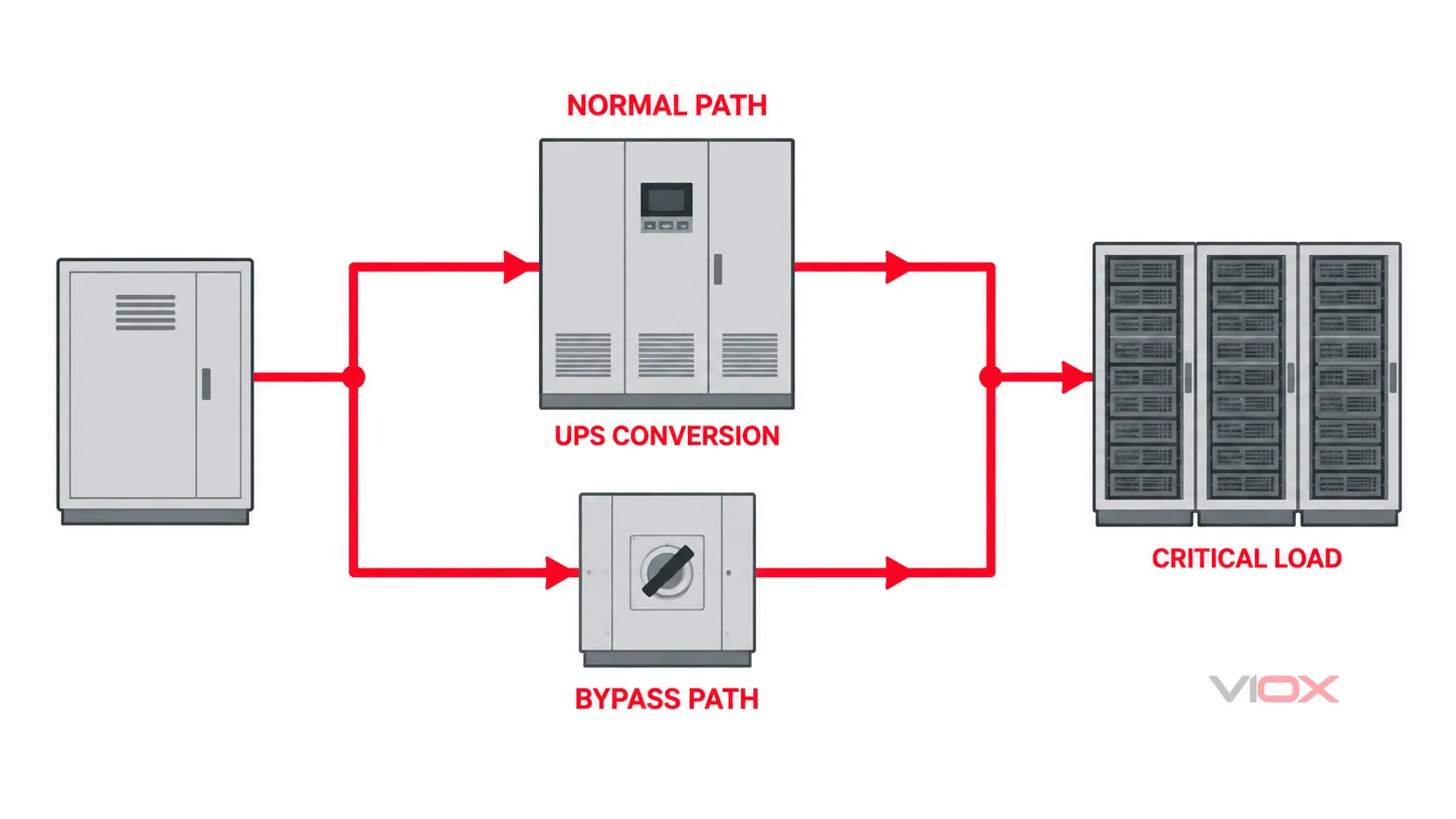
حماية الـ PDU، و الـ RPP، ومسارات التغذية (Busway)، والخزائن (Rack)
يمكن أن يشمل توزيع مركز البيانات في اتجاه الحمل (downstream) وحدات توزيع الطاقة (PDUs) المعتمدة على محولات، ووحدات توزيع الطاقة بدون محولات، ولوحات توزيع الطاقة الفرعية (RPPs)، ولوحات التوزيع، ووحدات التفرع من قضبان التوصيل (busway)، ووحدات توزيع الطاقة في الخزانات (rack PDUs)، ومراقبة دوائر التفرع. تصف هذه الأسماء أدوار التوزيع؛ وهي لا تثبت وجود وظيفة محددة للحد من الاندفاعات الكهربائية.
حدد ما إذا كانت مرحلة المصب مبررة من خلال طرح أربعة أسئلة:
- هل هذه عقدة كهربائية متميزة؟ قد يؤدي وجود محول، أو مسار طويل، أو غرفة منفصلة، أو مغذٍ خارجي، أو حدود ربط جديدة إلى تغيير مستوى التعرض والإجهاد على طرف توصيل المعدات.
- ما الذي يجب حمايته عند تلك العقدة؟ حدد هدف تحمل النبضات أو حماية الشركة المصنعة لإلكترونيات وحدة توزيع الطاقة (PDU)، ومراقبة الفرع، ومعدات الحامل (Rack)، ومنافذ التحكم المتصلة.
- ما الذي تتركه مرحلة المنبع عند هذه العقدة؟ استخدم أدلة التنسيق للجهد والطاقة المثبتة، وليس ملصق جهاز المنبع وحده.
- هل يمكن لجهاز SPD المقترح في المصب أن يصمد وينسق؟ تأكد من مستوى الحماية، وواجب التفريغ، وملاءمة تيار القصر، والحماية الاحتياطية، ومسار التوصيل، وأدلة التنسيق مع الشركة المصنعة.
VIOX دليل تنسيق وتتابع SPD يطور بوابات التحقق الأربع تلك بالتفصيل. يستخدم دليل مركز البيانات هذا نفس الطريقة ولكنه لا يغني عن حسابات المشروع أو أدلة اقتران الأجهزة الدقيقة.
على مستوى الحامل (rack)، تأكد مما إذا كانت وحدة توزيع الطاقة الذكية (rPDU) تقوم ببساطة بتوزيع الطاقة، أو مراقبتها، أو تبديل المخارج، أو توفر أيضاً وظيفة حماية معلنة من زيادة التيار. المصطلحات التسويقية مثل مفلترة, مكيفةأو محمية ليست بدائل لمعيار الاختبار، وأنماط الحماية، وبيانات جهد التحديد، وتعليمات التنسيق.
احمِ مسارات البيانات والتحكم الموصلة بشكل منفصل
يمكن تنسيق حماية الطاقة بشكل صحيح بينما لا يزال العابر يعبر واجهة نحاسية للاتصالات أو المراقبة أو التحكم. قد تشمل المسارات ذات الصلة:
- إيثرنت والطاقة عبر الإيثرنت (PoE)؛;
- تغذيات الاتصالات ودوائر النواقل النحاسية؛;
- RS-485، وModbus، وBACnet، ووحدات الإدخال/الإخراج (I/O) عن بُعد؛;
- مستشعرات ووحدات تحكم نظام إدارة المباني (BMS)؛;
- واجهات الكشف عن الحريق، والتحكم في الوصول، وكاميرات المراقبة (CCTV)، وأنظمة الأمن؛;
- روابط مراقبة المولد، ومفتاح التحويل التلقائي (ATS)، ونظام الطاقة غير المنقطعة (UPS)، ووحدة توزيع الطاقة (PDU)، والبطاريات؛;
- عناصر تحكم محطة التبريد والمعدات الخارجية عن بُعد؛;
- الهوائيات، والكابلات المحورية، ودروع الكابلات المعدنية.
لا يمكن اختيار SPD للطاقة لهذه الواجهات. يجب أن يحافظ جهاز الحماية على الإشارة الطبيعية مع تحديد أنماط الاندفاع ذات الصلة. يتطلب ذلك الحد الأقصى للإشارة المستمرة أو جهد التغذية، أو التيار، أو التردد، أو معدل البيانات، أو النطاق الترددي، أو فقدان الإدخال، أو ترتيب الموصل/الزوج، أو التدريع، أو طريقة التأريض، أو الموصل، وبيانات الاختبار المعمول بها.
IEC 61643-21:2025 يغطي المتطلبات وطرق الاختبار لأجهزة SPD المتصلة بشبكات الاتصالات والإشارات، بما في ذلك الخطوط التي توفر الطاقة أيضاً مثل PoE. IEC 61643-22:2015 يتناول اختيارها وموقعها وتنسيقها وصيانتها. كما تتعامل IEEE مع أجهزة حماية الاندفاع الخاصة بتكنولوجيا المعلومات والاتصالات (ICT) كنطاق تطبيق منفصل في IEEE C62.43.1-2020.
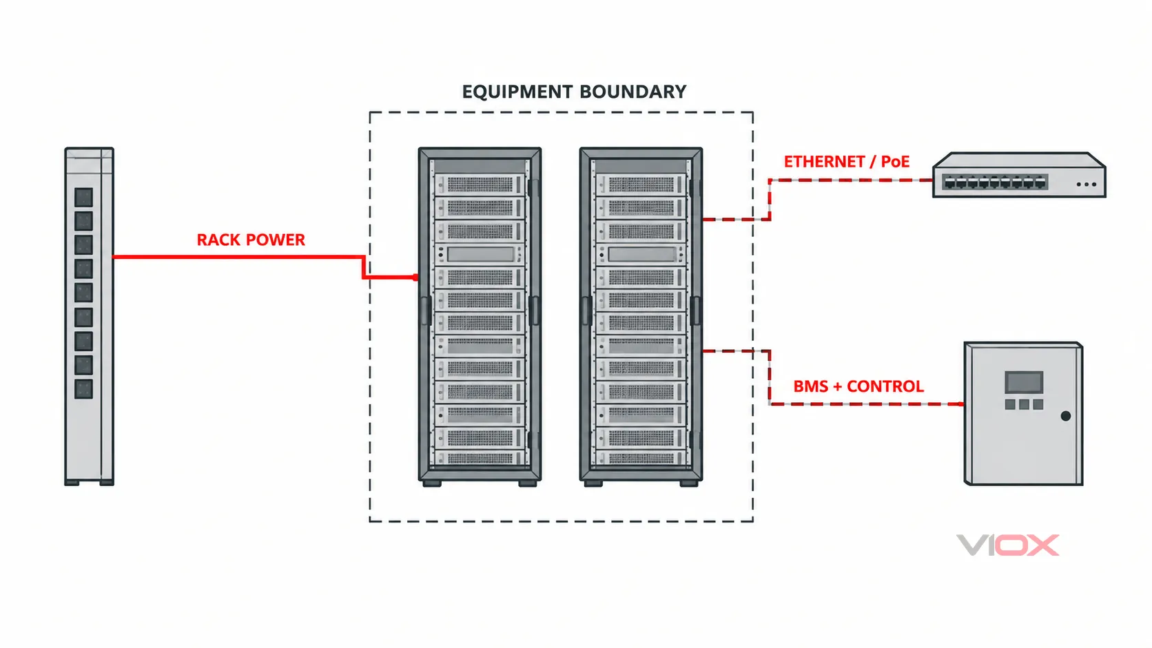
استخدم VIOX دليل اختيار واقي اندفاع التيار للإشارة لاختيار مستوى الواجهة. حيثما توفر الألياف الضوئية رابطاً غير موصل للكهرباء بشكل حقيقي، يمكنها إزالة مسار اندفاع واحد، ولكن لا تزال عناصر القوة المعدنية، والدروع، وموصلات الطاقة، والحاويات، ومسارات الربط تتطلب المراجعة.
حافظ على التكرارية A/B خلال كل حالة تشغيل
تغير التكرارية في مراكز البيانات مراجعة الاندفاع بطريقتين. أولاً، إنها تنشئ المزيد من المصادر ومسارات التوزيع. ثانياً، يمكن لحالات الصيانة أو الأعطال أن تضع المسارين المنطقيين مؤقتاً على مصدر مشترك في المنبع أو تتجاوز الحدود.
لكل مسار A/B، حدد:
- المصدر الطبيعي والمصدر البديل؛;
- حالة ATS أو لوحة المفاتيح الكهربائية؛;
- وحدة UPS، والدخل، والمسار الالتفافي (bypass)، والخرج؛;
- مسار PDU/RPP أو مجرى التغذية (busway)؛;
- تغذية الخزانة (rack) وتوصيل المعدات ذات الكابل المزدوج؛;
- نقاط التأريض والربط المشتركة؛;
- عناصر التحكم والمراقبة والاتصالات النحاسية المتقاطعة؛;
- كل حالة يتم فيها عزل المكون لأغراض الصيانة.
ثم اسأل عما إذا كان فشل أحد أجهزة SPD، أو تشغيل فاصل، أو تشغيل جهاز احتياطي، أو عزل الصيانة يمكن أن يؤدي إلى إزالة الحماية من كلا المسارين. لا تتطلب الموثوقية بالضرورة وجود أجهزة مكررة في كل نقطة مادية، ولكن يجب أن يوضح سجل التصميم حالات التعرض وفقدان الحماية التي يمكن لكل مسار تحملها.
حدد الأدلة، وليس مجرد رقم الـ kA
لكل جهاز حماية من اندفاع التيار (SPD) مقترح يعمل بالتيار المتردد (AC)، اجمع مجموعة متسقة من المتطلبات. تعتمد مسميات التصريح الدقيقة على إطار العمل المطبق سواء كان IEC أو UL أو الإطار المحلي، لذا لا تقارن كميات الاختبار غير المتشابهة وكأنها قابلة للتبديل.
| المتطلبات | ما يجب تسجيله | لماذا يغير ذلك القرار |
|---|---|---|
| النظام | الجهد الاسمي، التردد، الأطوار، ترتيب التأريض، أقصى جهد مستمر عبر كل نمط | يحدد الجهد المتوافق وترتيب نمط الحماية |
| الموقع والوظيفة | حدود المنشأة، سياق الصواعق، العقد في المنبع/المصب، فئة/نوع SPD المطبق | يحدد واجب الاندفاع المخصص للموقع |
| أداء الحماية | أعلى, ، VPR، جهد التحديد المقاس، أو التصريح الخاص بنمط معين |
يدعم هدف جهد طرف توصيل المعدات |
| واجب التفريغ | Iimp, في, Imax, ، تيار التفريغ الاسمي، أو بيانات النبضة القابلة للتطبيق |
يصف الأداء تحت واجبات اختبار مختلفة؛ القيم ليست قابلة للتبديل |
| حالات الأعطال | تيار القصر الكهربائي المتوقع، إعلان القصر الكهربائي لـ SPD مثل SCCR أو Isccr, ، الحماية الاحتياطية المطلوبة |
يمنع استخدام SPD بما يتجاوز أدلة تيار العطل وجهاز الحماية الخاص به |
| سلوك TOV | سلوك الجهد الزائد المؤقت المعلن للنظام والأنماط | يعالج إجهاد تردد الطاقة بشكل منفصل عن أداء النبضة |
| التنسيق | نماذج دقيقة للمنبع/المصب، الفصل، فك الارتباط، وأدلة التنسيق مع الشركة المصنعة | يوضح ما إذا كانت المراحل المتعددة تعمل كنظام واحد معتمد |
| التركيب | طول موصل التوصيل، المسار، مساحة الحلقة، طريقة التفريع، الحاوية، والظروف البيئية | يمكن أن تؤدي حثية الموصل المركب ومساره إلى رفع الجهد عند المعدات المحمية |
| القابلية للصيانة | مؤشر مرئي، منطق التلامس عن بُعد، وحدة قابلة للاستبدال، طريقة العزل، استراتيجية قطع الغيار | يحدد كيفية اكتشاف فقدان الحماية واستعادتها |
استخدم دليل VIOX لـ قراءة ورقة البيانات الخاصة بـ SPD عند ترجمة هذه الحقول في طلب عرض أسعار (RFQ). لا تقم بإضافة المنبع والمصب أعلى القيم، تعادل Imax مع Iimp, ، أو تعامل مع أكبر رقم kA كدليل على أقل جهد حماية مركب.
التحكم في متغيرات التركيب
حتى جهاز SPD المختار بشكل صحيح يمكن أن يكون أداؤه ضعيفاً عندما يضيف مسار توصيله جهداً إضافياً أو عندما يسلك تيار الاندفاع مسار ربط غير محكوم. راجع حلقة التوصيل الكاملة:
- حافظ على موصلات توصيل SPD قصيرة ومباشرة بقدر ما تسمح به طريقة التركيب المعتمدة؛;
- تجنب الحلقات غير الضرورية، والانحرافات الحادة في المسار، والفصل بين الموصلات التي يجب أن تشترك في مسار تيار الاندفاع؛;
- نسق توصيلات الخط، والمحايد، والتأريض الوقائي، والربط مع نظام التأريض وأنماط الحماية المطلوبة؛;
- تحقق من المصهر الاحتياطي أو قاطع الدائرة وتيار العطل المحتمل عند نقطة التوصيل الفعلية؛;
- حافظ على ربط حماية الطاقة والإشارة بالمرجع المقصود دون إنشاء مسار غير مراجع بين المناطق؛;
- اتبع التعليمات الخاصة بـ SPD، ولوحة التوزيع، وUPS، وATS، وPDU، ومعدات الإشارة بدقة.
IEC 62305-4:2024 يتناول تدابير الحماية من الاندفاعات الكهربائية على مستوى النظام للأنظمة الكهربائية والإلكترونية داخل المنشآت. ويشمل نطاقه التصميم، والتركيب، والفحص، والصيانة، والاختبار، وليس فقط اختيار المكون الوقائي.
جعل فقدان الحماية مرئياً
يمكن لـ SPD فصل عنصر الحماية التالف بينما تظل دائرة مركز البيانات تحت الجهد. قد يستمر الحمل في العمل مع حماية من الاندفاعات الكهربائية منخفضة أو معدومة، لذا فإن المؤشر الأخضر الذي يظهر أثناء التشغيل ليس ضماناً لمدى الحياة.
تعريف:
- الحالة الطبيعية وحالة الإنذار لكل مؤشر مرئي؛;
- منطق التوصيل مفتوح عادةً (NO)، ومغلق عادةً (NC)، والمشترك (COM) لأي تلامس عن بُعد؛;
- أي نظام إدارة مباني (BMS)، أو نظام التحكم الإشرافي وتحصيل البيانات (SCADA)، أو مدخل إنذار يستقبل الإشارة؛;
- ما إذا كان الإنذار يحدد وحدة واحدة، أو نمطاً واحداً، أو تجميعة واحدة، أو مجرد حالة مشتركة؛;
- استجابة الفحص، وطريقة العزل الآمن، وقطعة الغيار، والتحقق من استعادة التشغيل؛;
- كيفية الحفاظ على حالة الحماية أثناء الصيانة المخطط لها أو استبدال الوحدات.
يُبلغ طرف التوصيل عن بُعد بشكل عام عن حالة الجهاز؛ فهو لا يقيس مقدار الاندفاع الكهربائي ولا يحسب بدقة العمر التشغيلي المتبقي. قم بتوجيه منطق الحالة التفصيلي إلى VIOX دليل الإشارات عن بُعد لـ SPD وتخطيط الاستبدال القائم على الحالة إلى دليل دورة حياة SPD الصناعي وتقادم MOV.
ورقة عمل مراجعة الخط الأحادي لـ SPD في مراكز البيانات
أكمل صفاً واحداً لكل مصدر، وتجاوز، وتوزيع، وحامل (rack)، وحدود إشارة موصلة. كرر الصفوف للمسارين A و B وللحالات التي تغير مسار التيار بشكل جوهري.
| المجال | إدخال المشروع |
|---|---|
| معرف الحدود ومرجع الخط الواحد | [لوحة / قضيب توزيع / مغذي / واجهة] |
| حالات التشغيل باستخدام هذا المسار | [عادي / مولد / تجاوز ثابت / تجاوز صيانة / بطارية / أخرى] |
| المصدر وترتيب التأريض | [مرافق / مولد / مخرج UPS / نظام مشتق؛ TN / TT / IT / خاص بالمشروع] |
| الجهد الاسمي والجهد المستمر الأقصى | [القيمة ووضع الحماية] |
| المعدات المتصلة وهدف التحمل | [المعدات / التحمل المعلن / هدف التصميم] |
| التعرض الخارجي والمولد محلياً | [سياق البرق / التحويل / المسار الخارجي / المسار المزدوج] |
| وظيفة SPD المقترحة والإطار المطبق | [الطاقة أو الإشارة؛ النوع/الفئة/معيار الاختبار] |
| أدلة مستوى الحماية | [Up / VPR / جهد التحديد المقاس / بيانات تحديد الإشارة] |
| أدلة واجب التفريغ | [Iimp / In / Imax / Uoc / بيانات اختبار الإشارة المطبقة] |
| تيار العطل المحتمل وأدلة القصر الكهربائي لـ SPD | [تيار العطل / SCCR / Isccr / إقرار آخر] |
| ترتيب الحماية الاحتياطية وفصل التيار | [الجهاز / التصنيف / تعليمات الشركة المصنعة] |
| أدلة التنسيق بين الأجهزة في المنبع والمصب | [الموديلات الدقيقة / جدول / تركيبة مختبرة / حسابات] |
| مسار التوصيل والربط | [طول الموصل / المسار / نقطة ربط التأريض الوقائي PE / معالجة الدرع] |
| الحالة وطريقة الصيانة | [مؤشر / تلامس عن بُعد / دخل إنذار / وصول للاستبدال] |
| المسألة المفتوحة والمراجع المسؤول | [غير معروف / مستند مطلوب / المالك / تاريخ الاستحقاق] |
كتلة طلب عرض السعر (RFQ)
أرسل المعلومات التالية عند طلب اختيار أو عرض سعر لـ SPD:
المشروع / السوق:
معيار أو كود التركيب المطبق:
مراجعة المخطط أحادي الخط:
معرف الحدود وموقع التركيب:
مسارات المصدر العادي والبديل ومسار التجاوز (bypass):
جهد النظام والتردد والأطوار:
ترتيب التأريض وأنماط الحماية:
الحماية من الصواعق / سياق التعرض:
تيار القصر الكهربائي المتوقع عند نقطة التوصيل:
نوع SPD المطلوب أو فئة الاختبار، إذا تم تصميمه مسبقاً:
مستوى Up / VPR / هدف جهد التحديد المطلوب:
قيمة Iimp / In / Imax المطلوبة أو واجب الاختبار المطبق:
متطلبات المصهر الاحتياطي أو قاطع الدائرة:
نماذج SPD في المنبع والمصب للتنسيق:
مسار موصل التوصيل ومساحة التركيب المتاحة:
متطلبات المؤشر المرئي / التلامس عن بُعد:
واجهات الطاقة، وPoE، والبيانات، والتحكم، والمراقبة:
الشهادات والتقارير والتعليمات الخاصة بالنموذج المطلوب:
الكمية، ووجهة التسليم، وجدول المشروع:
يجب أن تظل الحقول غير المعروفة محددة كـ “غير معروف” بدلاً من استبدالها بتصنيف عام مثل "درجة مراكز البيانات".
قاعدة التصميم النهائية
تكتمل الحماية من الاندفاعات الكهربائية في مراكز البيانات فقط عندما تتم مراجعة كل مسار مكهرب وموصل في كل حالة تشغيل ذات صلة. قد يتضمن التصميم الصحيح مرحلة دخول، ومراحل في المصب، وواقيات خاصة بالواجهات، ولكن لا يمكن اختيار العدد والتصنيفات من مخطط مستويات عالمي.
قم ببناء الهيكل أولاً. ثم تحقق من حماية الجهد، وتنسيق الطاقة، وتأثيرات المسافة والتوصيل، والتوافق مع القصر الكهربائي، وحالات التجاوز، وواجهات الإشارة، وقابلية الصيانة لمجموعة المعدات المحددة.
لتقييم المنتج، قارن جدول الأدلة مع المتاح مجموعة أجهزة الحماية من الاندفاع الكهربائي VIOX. للحصول على قائمة مختصرة خاصة بالمشروع، أرسل مراجعة الخط الواحد المكتملة وكتلة طلب عرض الأسعار (RFQ) إلى [email protected]. يجب تأكيد ملاءمة منتج VIOX من وثائق الطراز الدقيقة؛ فظهوره في هذا الدليل لا يثبت التوافق مع كل نظام من أنظمة مراكز البيانات.
المراجع الفنية
- ISO/IEC 22237-3:2021 — مرافق وبنى تحتية لمراكز البيانات، الجزء 3: توزيع الطاقة
- IEC 61643-01:2024 — المتطلبات العامة وطرق الاختبار لأجهزة حماية التيار المتردد والمستمر (SPD) ذات الجهد المنخفض
- IEC 61643-11:2025 — أجهزة SPD المتصلة بأنظمة طاقة التيار المتردد AC ذات الجهد المنخفض
- IEC 61643-12:2020 — مبادئ الاختيار والتطبيق لأجهزة الحماية من اندفاع التيار (SPD) للتيار المتردد (AC)
- IEC 62305-4:2024 — الأنظمة الكهربائية والإلكترونية داخل المنشآت
- IEC 61643-21:2025 — أجهزة حماية من اندفاع التيار (SPD) المتصلة بشبكات الاتصالات والإشارات
- IEC 61643-22:2015 — مبادئ الاختيار والتطبيق لأجهزة حماية التيار المندفع (SPD) لشبكات الإشارات
- IEEE C62.43.1-2020 — أجهزة حماية التيار المندفع لدوائر تكنولوجيا المعلومات والاتصالات (ICT)