Ezen az oldalon
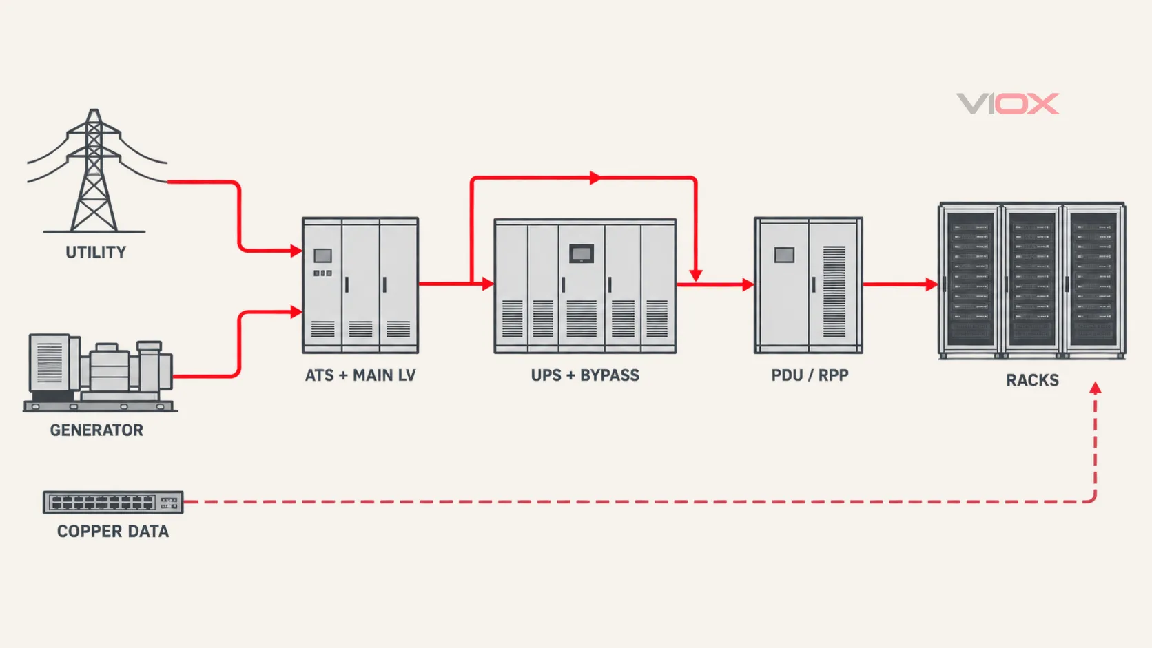
Az adatközponti túlfeszültség-védelmi tervezésnek minden vezető utat követnie kell – nem csupán egy általános háromszintű terméklistát. Kezdje az egyvonalas rajzzal, és kövesse végig a közüzemi betáplálást, a generátorforrást, az automatikus átkapcsoló berendezést (ATS), a fő kisfeszültségű kapcsolóberendezést, a szünetmentes tápegység (UPS) bemenetét és bypass ágát, a lefelé irányuló elosztást, az áramelosztó egységet (PDU) vagy a távoli elosztószekrényt (RPP), a rack betápokat, valamint a szabadon álló réz adat- vagy vezérlőinterfészeket.
Kezeljen minden átmenetet lehetséges védelmi határként. Rendeljen hozzá egy túlfeszültség-védelmi eszköz (SPD) csak a rendszerfeszültség, a földelési elrendezés, a várható túlfeszültség-kitettség, a berendezés tűrőképességi célkitűzése, a várható rövidzárlati áram, a csatlakozási útvonal és a koordinációs bizonyítékok megerősítése után. Egy UPS, egy rack PDU vagy egy magas kA-érték önmagában nem teszi teljessé ezt a felülvizsgálatot.
Tervezési határ: Ez az útmutató egy koncepcionális mérnöki munkafolyamat, nem pedig kapocsbekötési utasítás vagy tervjóváhagyás. Az adatközponti elektromos rendszerek több feszültség alatt álló forrást, tárolt energiát, bypass útvonalakat és magas zárlati szinteket tartalmazhatnak. A végleges tervezés, telepítés, tesztelés és karbantartás szakképzett személyzetet, a jóváhagyott egyvonalas kapcsolási rajzot, a berendezésekre vonatkozó utasításokat, az alkalmazandó szabványokat és a projektspecifikus vizsgálatokat igényel.
A teljes adatközponti túlfeszültség-útvonal feltérképezése
Az adatközpont rendelkezésre állása a teljes energiaellátási architektúrától függ, nem csupán a közüzemi betáplálástól. A normál üzemi útvonal áthaladhat főelosztón, UPS-en, PDU-n, RPP-n vagy sínrendszeren, mielőtt elérné az informatikai berendezéseket. Forráskimaradás vagy karbantartás esetén az energia áthaladhat generátoron, tartalék betápláláson, statikus bypasson, karbantartási bypasson vagy egy második A/B elosztási útvonalon.
A túlfeszültség-védelmi felülvizsgálatnak ezért minden olyan állapotot le kell fednie, amelyben a berendezés feszültség alatt maradhat:
Közüzemi forrás ── Fő kisfeszültségű (LV) elosztó ── UPS bemenet ── UPS kimenet ── PDU/RPP ── A rack
      │                    │                    ▲
      │                    └── UPS bypass ──────┘
      │
Generátor ── Generátor kapcsolóberendezés ── ATS ──────┘

Tartalék forrás/útvonal ── B elosztó ── B UPS ── B elosztás ── B rack

Külső réz alapú szolgáltatások ── Hálózat / BMS / tűzvédelmi / biztonsági / hűtésvezérlők ── IT berendezések
Ez egy határolási térkép, nem pedig szabványos topológia. Egyes létesítmények központosított UPS-rendszereket használnak, mások elosztott vagy moduláris UPS-architektúrákat, és az a pont, ahol a nullavezető kialakításra vagy kapcsolásra kerül, eltérő lehet. ISO/IEC 22237-3:2021 a tápegységeket, a belső elosztást, a távközlési egyenpotenciálra hozást, a villámvédelmet és az áramminőség-mérést az adatközponti energiaelosztás hatókörébe helyezi. Ez a rendszerszemlélet az oka annak, hogy egy SPD-vizsgálat nem állhat meg a betáplálási pontnál. A szélesebb körű VIOX Adatközpontok és távközlés alkalmazási oldal térképezi a túlfeszültség-védelmet az átkapcsolás, felügyelet, ágvédelem és elosztás mellett, anélkül, hogy ez kiváltaná az SPD tervfelülvizsgálatát.
A nyolc határvonal, amelyet jelölni kell az egyvonalas kapcsolási rajzon
| Határvonal | Elsődleges felülvizsgálati kérdés | Jóváhagyás előtt bizonyíték szükséges | Gyakori mulasztás |
|---|---|---|---|
| Közüzemi betáp és fő kisfeszültségű elosztóberendezés | Milyen külső túlfeszültség-terhelés érheti a létesítmény betáplálási pontját? | Betáplálási és földelési elrendezés, villámvédelmi környezet, névleges és maximális tartós feszültség, alkalmazandó SPD osztály/típus, védelmi szint, zárlati áram és tartalékvédelem adatai | Kiválasztás kizárólag a legnagyobb kisütési áramérték alapján |
| Generátor és ATS útvonal | Létrehozhat-e külön kitettséget az alternatív forrás, a szabadon vezetett betáp, a kapcsolási elrendezés vagy a potenciálkiegyenlítési kialakítás? | Generátor és ATS egyvonalas rajz, vezetőútvonal, forrásjellemzők, nullavezető kezelése, hibaállapotok, berendezés-utasítások | Csak a hálózati betáp védelme |
| UPS normál bemenet | Milyen tranziens érheti el az egyenirányítót vagy a bemeneti fokozatot? | UPS bemeneti ellenállóképesség és utasítások, upstream SPD adatok, telepített vezetőútvonal, forrás- és hibaállapotok | Feltételezve, hogy az UPS címkéje igazolja a megfelelő külső védelmet |
| UPS bypass útvonal | A bypass képes ellátni a terhelést a normál konverziós útvonal kikerülésével? | Statikus és karbantartási bypass topológia, bypass-forrás eredete, kapcsolási állapotok, gyártói követelmények | A normál UPS útvonal áttekintése, de a bypass nélkül |
| UPS kimenet és a lefelé irányuló elosztás | Szükséges-e egy további SPD fokozat a berendezés kapcsainál támasztott célkitűzés eléréséhez? | Kimeneti topológia, galvanikus leválasztás vagy levezetett nulla, ahol alkalmazható, kábeltávolság, a lefelé irányuló berendezések ellenállóképessége, gyártói kompatibilitás | Kimeneti SPD telepítése megszokásból, az UPS viselkedésének ellenőrzése nélkül |
| PDU, RPP, síncsatorna és leágazó elosztás | Az elosztási határ különálló védett zónát vagy hosszú, lefelé irányuló útvonalat szolgál ki? | Transzformátoros vagy transzformátor nélküli topológia, leágazási elrendezés, hibaáram, berendezés-ellenállóképesség és koordinációs bizonyítékok | Feltételezve, hogy minden PDU megfelelő túlfeszültség-védelemmel rendelkezik |
| Rack tápellátások | Javíthatja-e a felhasználási ponton történő fokozat a végső berendezés-kapocs célkitűzést anélkül, hogy ellenőrizetlen kaszkádot hozna létre? | Rack-tápfeszültség, PDU-jellemzők, végső berendezés-interfész, upstream/downstream koordinációs adatok | Egy szokásos rack-elosztó kezelése hitelesített Type 3 SPD-ként |
| Réz adatátviteli, felügyeleti és vezérlő interfészek | Bejuthat vagy kijuthat-e túláram vezető, nem tápellátást biztosító útvonalon keresztül? | Interfészfeszültség, áramerősség, sávszélesség/adatátviteli sebesség, PoE-osztály (ahol releváns), érintkező/érpár kiosztás, árnyékolás, potenciálkiegyenlítés, csatlakozó, vizsgálati szabvány | Az AC tápellátás védelme a szabadon hagyott réz interfészek felülvizsgálata nélkül |
Az UPS nem minősül túlfeszültség-védelmi specifikációnak
A UPS és az SPD különböző elsődleges problémákat old meg. A UPS energiatárolást biztosíthat az áramkimaradás áthidalására, és topológiájától függően szabályozhatja vagy kondicionálhatja a tápellátást. Az SPD-t a tranziens feszültség korlátozására és a túláram elvezetésére értékelik meghatározott vizsgálati körülmények között. Egyes UPS modellek belső túlfeszültség-korlátozó alkatrészeket tartalmaznak, de ezek jelenléte, védelmi módjai, vizsgálati terhelhetősége, leválasztó elrendezése és koordinációs határértékei modellenként eltérőek.
Kérje el a pontos UPS dokumentációt, ahelyett, hogy csak a szóra hagyatkozna UPS:
- Mely bemeneti, bypass és kimeneti kapcsok állnak rendelkezésre?
- Mely útvonalak maradnak csatlakoztatva normál, akkumulátoros, statikus bypass, karbantartási bypass és hibaállapotokban?
- A gyártó nyilatkozik-e a belső túlfeszültség-védelemről, és milyen vizsgálati módszer, illetve üzemmódok szerint?
- Milyen külső SPD-elrendezések megengedettek vagy kötelezőek?
- Befolyásolhatja-e egy utólag beépített SPD a szivárgóáram-felügyeletet, a szigetelésfelügyeletet, a szűrőket, a forráskompatibilitást vagy a védelmi koordinációt?
- A kimenet különálló, transzformátorral leválasztott, transzformátor nélküli, vagy olyan módon kapcsolt, amely megváltoztatja a földelési referenciát?
A válasz eltérő lehet a kettős konverziójú, vonali interaktív, moduláris, transzformátoros és transzformátor nélküli rendszerek esetében. Ne helyezzen SPD-t egy UPS kimenetére pusztán azért, mert egy rajz hiányosnak tűnik. Ellenőrizze a tényleges kimeneti áramkört, a gyártói utasításokat, a normál és bypass állapotokat, valamint a downstream célkitűzést.
Az SPD emellett nem korrigálja a tartós túlfeszültséget, az alulfeszültséget, a frekvenciahibát, a harmonikus torzítást, a fáziskiesést vagy a helytelen átkapcsolási parancsot. Ezekhez a körülményekhez megfelelő felügyeleti, vezérlési, védelmi és teljesítményminőségi funkciók szükségesek.
A közüzemi hálózat, a generátor és az ATS külön forrásútvonalként való vizsgálata
A közüzemi és a generátoros betáplálások gyakran egy ATS-nél találkoznak, de nem ugyanazt a túlfeszültség-útvonalat képviselik. A vezetőik útvonala, kitettsége, forrásimpedanciája, nulla-elrendezése és a várható rövidzárlati feltételek eltérőek lehetnek.
Közüzemi és főelosztó határfelület
A létesítmény betáplálási pontján állapítsa meg, hogy a tervezésnek foglalkoznia kell-e villámárammal, hálózati kapcsolási tranzienssel vagy egyéb vezetett zavarral. Határozza meg az alkalmazandó telepítési keretrendszert és a külső villámvédelmi rendszerrel való kapcsolatot. Ha villámáram juthat át a határon, a szükséges terhelhetőség nem következtethető ki kizárólag egy lejjebb lévő Type 2 eszközből vagy egy nagy Imax értékből.
IEC-alapú AC rendszerek esetében, IEC 61643-11:2025, együtt használva a IEC 61643-01:2024, meghatározza az AC kisfeszültségű SPD-k termékkövetelményeit, vizsgálatait és névleges értékeit. IEC 61643-12:2020 foglalkozik a kiválasztással, az elhelyezéssel, a működéssel és a koordinációval. A terméknyilatkozat és a telepített alkalmazás külön bizonyítéki rétegek; mindkettő szükséges.
Generátor és ATS határ
Ne használjon univerzális kábeltávolsági szabályt annak eldöntésére, hogy a generátor oldal vagy az ATS kimenet igényel-e további SPD-t. A távolság megváltoztathatja a kitettséget, a csatolást, az oszcillációt és a lejjebb lévő védelmi fokozat értékét, de nem helyettesíti a tényleges útvonal- és koordinációs vizsgálatot.
Áttekintés:
- hogy a generátor betápja beltéri, kültéri, föld alatti, felső vezetékes, vagy villámáram-útvonalak közelében vezetett-e;
- hogy a generátor segédberendezései, vezérlései, fűtései, töltői vagy kommunikációs vezetékei hoznak-e létre további csatlakozási pontokat;
- az ATS átkapcsolási módja és minden csatlakoztatott forrás;
- a kapcsolt vagy nem kapcsolt nulla kezelése és az ebből adódó védelmi módok;
- a várható rövidzárlati áram a hálózati és a generátoros üzemmódban;
- hogy az egyik oldalon lévő SPD csatlakoztatva marad-e és hatékony-e az ATS minden állapotában;
- hogy az ATS gyártója meghatározza-e a megengedett SPD-elhelyezéseket vagy csatlakoztatási elrendezéseket.
A kapcsolási események a tranziens környezet részét képezhetik, de egy SPD nem javítja meg a hibás ATS-t, és nem szabályozza a helytelen tartós kimenetet. A tranziens védelmet tartsa elkülönítve az átkapcsolás-vezérléstől, a feszültség-/frekvenciafelügyelettől, a túláramvédelemtől és a generátorvédelemtől.
Az UPS normál, bypass és karbantartási állapotait egyetlen tervezési problémaként kezelje
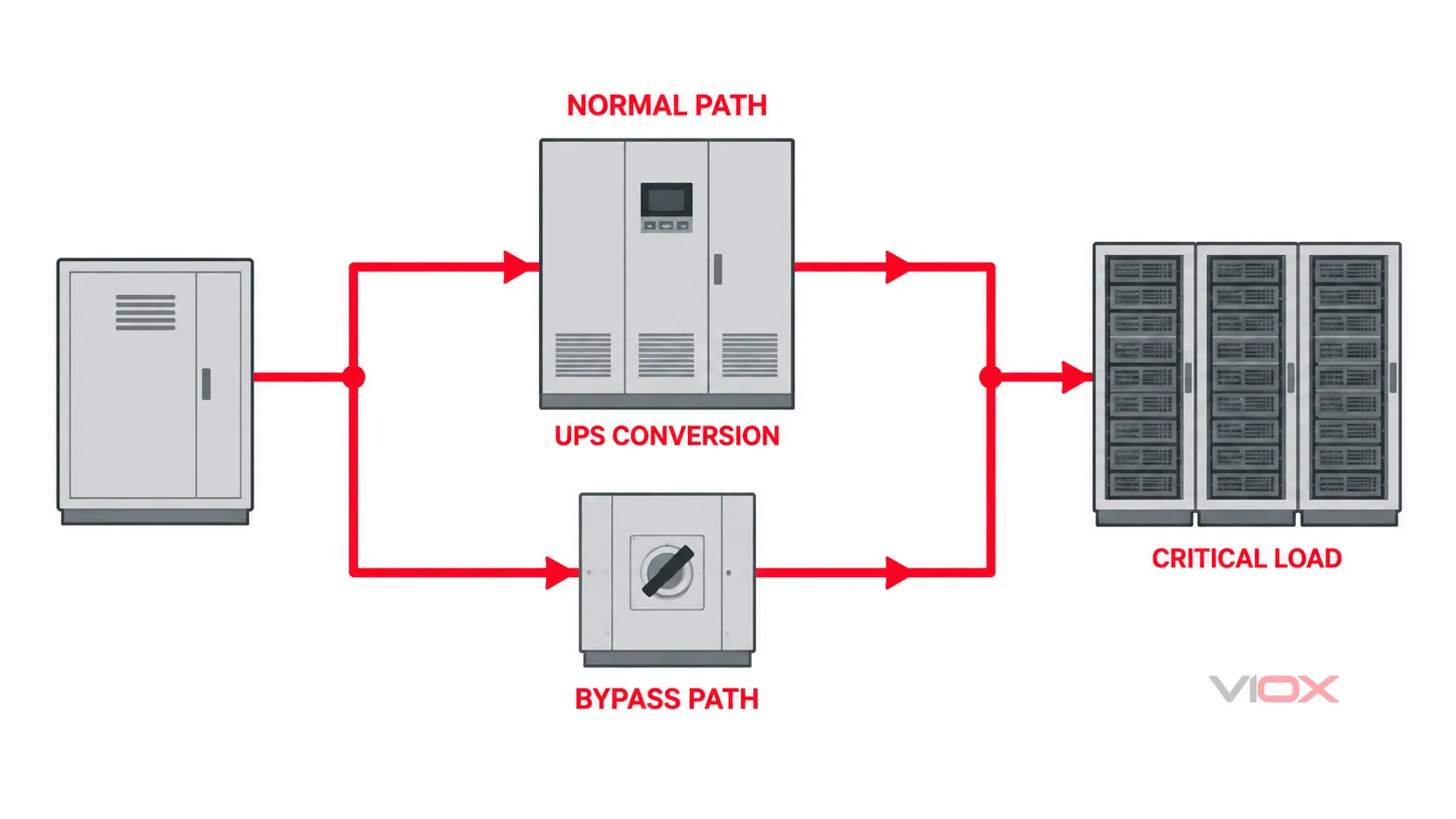
A bypass ág a legfontosabb adatközpont-specifikus ok, amiért nem szabad általános elosztói SPD-elrendezést alkalmazni. Amikor az UPS statikus bypassra vált, vagy amikor a technikusok karbantartási bypassba helyezik, a kritikus terhelés olyan útvonalon keresztül kaphat tápellátást, amely kikerüli a normál átalakítási lánc egy részét.
Minden egyes UPS-modulhoz vagy rendszerhez készítsen állapot táblázatot:
| Működési állapot | Forrás-terhelés útvonal | Még csatlakoztatott SPD-határok | Kötelező ellenőrzés |
|---|---|---|---|
| Normál átalakítás | Normál forrás → UPS bemenet/átalakítás → UPS kimenet | Projekt-specifikus | Bemeneti és kimeneti topológia, belső védelem, külső SPD-kompatibilitás |
| Akkumulátoros üzemmód | Energiatároló forrás → inverter → UPS kimenet | Projekt-specifikus | Kimeneti referencia, csatlakoztatott bypass vezetők, fogyasztói oldali védelem állapota |
| Statikus bypass | Bypass forrás → statikus kapcsoló → terhelés | Megkerülheti a normál átalakítási útvonalat | Bypass-forrás kitettsége és védelmi útvonala |
| Karbantartási bypass | Karbantartási bypass → lefelé irányuló elosztás | Lehetővé teszi az UPS és belső védelmének leválasztását | A védelem az UPS leválasztása alatt is megmarad |
| Alternatív forrású üzemmód | Generátor vagy második közüzemi betáp → ATS/kapcsolóberendezés → UPS vagy bypass | Megváltoztathatja a forrás zárlati áramát és a nullavezető referenciáját | Az SPD rövidzárlati megfelelősége és védelmi módjai ebben az állapotban |
Ha az A és B útvonal kettős tápkábelű IT-berendezést lát el, töltse ki ezt a táblázatot mindkét útvonalra vonatkozóan. Az A útvonalon lévő eszköz nem védi a B útvonalat pusztán azért, mert a két útvonal ugyanabban a rackben végződik.
PDU, RPP, síncsatorna és rack-szekrény védelem
Az adatközponti elosztás alsóbb szintjei tartalmazhatnak transzformátoros PDU-kat, transzformátor nélküli PDU-kat, RPP-ket, elosztótáblákat, síncsatorna leágazó egységeket, rack PDU-kat és áramköri felügyeletet. Ezek az elnevezések az elosztási szerepköröket írják le; nem igazolják a konkrét túlfeszültség-korlátozó funkciót.
Döntse el, hogy indokolt-e az alsóbb szintű fokozat, a következő négy kérdés megválaszolásával:
- Ez egy különálló elektromos csomópont? Egy transzformátor, hosszú vezetékszakasz, külön helyiség, külső betáplálás vagy új potenciálkiegyenlítési határ megváltoztathatja a kitettséget és a berendezés kapcsain fellépő igénybevételt.
- Mit kell védeni az adott csomópontban? Határozza meg a PDU elektronikájára, az áramköri felügyeletre, a rack-berendezésekre és a csatlakoztatott vezérlőportokra vonatkozó impulzusállósági vagy gyártói védelmi célkitűzést.
- Mit hagy hátra a felsőbb szintű fokozat ebben a csomópontban? Használja a beépített feszültség- és energia-koordinációs bizonyítékokat, ne csak a felsőbb szintű eszköz címkéjét.
- Képes-e a javasolt lefelé irányuló SPD a túlélésre és a koordinációra? Erősítse meg a védelmi szintet, a kisütési terhelhetőséget, a zárlati áramra való alkalmasságot, a tartalék védelmet, a csatlakoztatási útvonalat és a gyártói koordinációt igazoló dokumentumokat.
A VIOX SPD koordinációs és kaszkádolási útmutató részletesen kidolgozza ezt a négy ellenőrzési kaput. Ez az adatközponti útmutató ugyanazt a módszert alkalmazza, de nem helyettesíti a projekt számításait vagy a pontos eszközpárra vonatkozó igazolást.
A rack szinten erősítse meg, hogy az rPDU csupán elosztja az energiát, felügyeli azt, kapcsolja a kimeneteket, vagy deklarált túlfeszültség-védelmi funkciót is biztosít. Az olyan marketing kifejezések, mint a szűrt, kondicionált, vagy védett nem helyettesítik a vizsgálati szabványt, a védelmi módokat, a korlátozási feszültségre vonatkozó adatokat és a koordinációs utasításokat.
A vezetőképes adat- és vezérlőútvonalak külön védelme
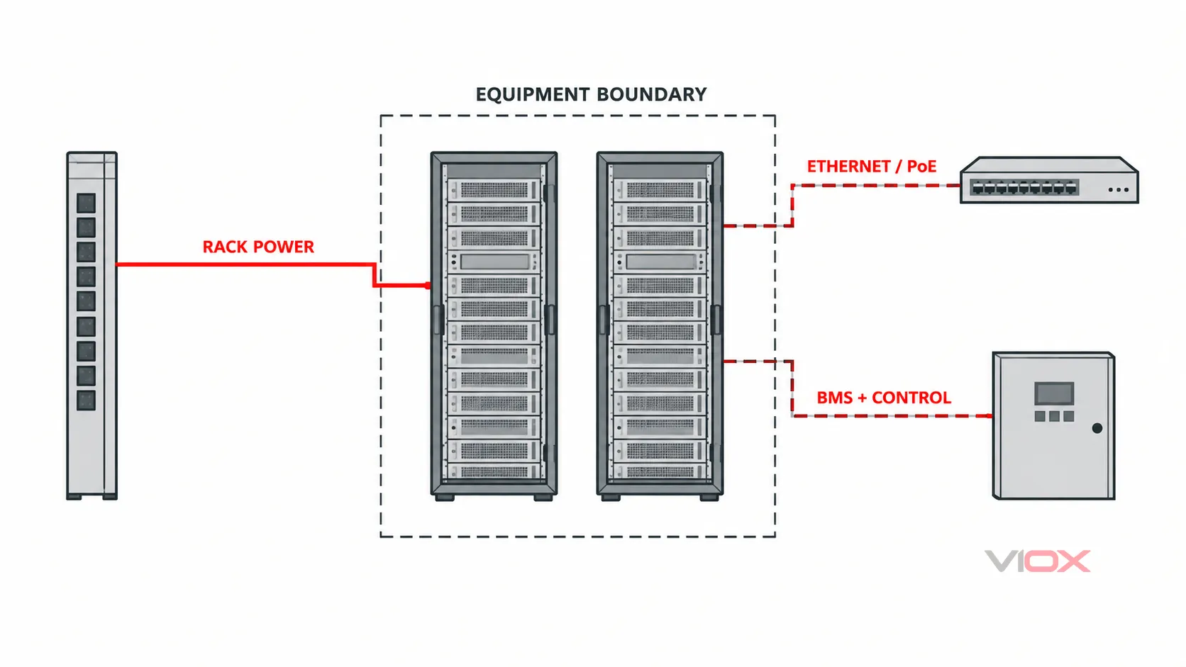
Az áramellátás védelme megfelelően koordinálható, miközben egy tranziens továbbra is áthalad egy réz alapú kommunikációs, felügyeleti vagy vezérlő interfészen. A releváns útvonalak a következők lehetnek:
- Ethernet és Power over Ethernet (PoE);
- távközlési betáplálások és réz alapú vivőfrekvenciás áramkörök;
- RS-485, Modbus, BACnet és távoli I/O;
- épületfelügyeleti rendszer (BMS) érzékelők és vezérlők;
- tűzjelző, beléptető, CCTV és biztonsági interfészek;
- generátor, ATS, UPS, PDU és akkumulátor-felügyeleti kapcsolatok;
- hűtőüzemi vezérlések és távoli kültéri berendezések;
- antennák, koaxiális kábelek és fém kábeltakarások.
Ezekhez az interfészekhez nem választható tápellátási SPD. A védőeszköznek meg kell őriznie a normál jelet, miközben korlátozza a vonatkozó túlfeszültség-módokat. Ehhez szükség van a maximális folyamatos jel- vagy tápfeszültségre, áramerősségre, frekvenciára vagy adatátviteli sebességre, sávszélességre, beiktatási veszteségre, vezető/érpár elrendezésre, árnyékolásra, földelési módra, csatlakozóra és a vonatkozó vizsgálati adatokra.
IEC 61643-21:2025 a távközlési és jelzőhálózatokhoz csatlakoztatott SPD-k követelményeit és vizsgálati módszereit fedi le, beleértve azokat a vonalakat is, amelyek tápellátást is biztosítanak, mint például a PoE. IEC 61643-22:2015 foglalkozik azok kiválasztásával, elhelyezésével, koordinációjával és karbantartásával. Az IEEE az IKT túlfeszültség-védelmi eszközöket külön alkalmazási területként kezeli a következőben: IEEE C62.43.1-2020.
Használja a VIOX jelvezeték túlfeszültség-védelmi kiválasztási útmutatót az interfészszintű kiválasztáshoz. Ahol az optikai szál valóban nem vezető kapcsolatot biztosít, ott megszüntethet egy túlfeszültség-útvonalat, de a fém szilárdsági elemeket, árnyékolásokat, tápvezetékeket, burkolatokat és potenciálkiegyenlítő útvonalakat továbbra is ellenőrizni kell.
Az A/B redundancia megőrzése minden üzemállapotban
Az adatközponti redundancia két módon változtatja meg a túlfeszültség-vizsgálatot. Először is, több forrás- és elosztási útvonalat hoz létre. Másodszor, a karbantartási vagy hibaállapotok átmenetileg egy közös upstream forrásra vagy bypass határra helyezhetik mindkét logikai útvonalat.
Minden A/B útvonalhoz jelölje meg:
- normál és alternatív tápforrás;
- ATS vagy kapcsolóberendezés állapota;
- UPS modul, bemenet, bypass és kimenet;
- PDU/RPP vagy síncsatorna útvonala;
- rack betáp és két tápkábellel ellátott berendezés csatlakoztatása;
- közös földelési és potenciálkiegyenlítési pontok;
- keresztkötésű vezérlések, felügyelet és réz alapú kommunikáció;
- minden olyan állapot, amelyben egy alkatrész karbantartás céljából le van választva.
Ezután kérdezze meg, hogy egy SPD meghibásodása, szakaszoló működése, tartalék eszköz működése vagy karbantartási leválasztás megszüntetheti-e a védelmet mindkét ágon. A redundancia nem feltétlenül igényel kettőzött eszközöket minden fizikai ponton, de a tervezési dokumentációnak tartalmaznia kell, hogy az egyes ágak milyen kitettséget és védelemkiesési eseményt képesek elviselni.
Ne csak egy kA-értéket adjon meg, hanem bizonyítékot is
Minden tervezett AC tápellátású SPD esetében gyűjtsön össze egy konzisztens követelményrendszert. A pontos nyilatkozati nevek az alkalmazandó IEC, UL vagy helyi keretrendszertől függenek, ezért ne hasonlítson össze eltérő vizsgálati mennyiségeket, mintha azok felcserélhetők lennének.
| Követelmény | Mit kell rögzíteni | Miért változtatja meg a döntést |
|---|---|---|
| Rendszer | Névleges feszültség, frekvencia, fázisok, földelési elrendezés, maximális folyamatos feszültség az egyes módokon keresztül | Meghatározza a kompatibilis feszültség- és védelmi módú elrendezést |
| Pozíció és feladat | Létesítményhatár, villámvédelmi környezet, upstream/downstream csomópontok, alkalmazandó SPD osztály/típus | Meghatározza a helyszínhez rendelt túlfeszültség-terhelést |
| Védelmi teljesítmény | Fel, VPR, mért korlátozási feszültség vagy alkalmazandó mód-specifikus nyilatkozat |
Támogatja a berendezéskapocs-feszültség célkitűzést |
| Kisütési terhelhetőség | Iimp, Be, Imax, névleges kisütési áram vagy alkalmazható impulzusadatok |
Leírja a teljesítményt különböző vizsgálati feladatok esetén; az értékek nem cserélhetőek fel |
| Hibaállapotok | Várható rövidzárlati áram, SPD rövidzárlati nyilatkozat, mint például SCCR vagy Isccr, szükséges tartalék védelem |
Megakadályozza az SPD alkalmazását a hibaáramra és a védelmi eszközre vonatkozó bizonyítékokon túl |
| TOV viselkedés | Deklarált átmeneti túlfeszültség-viselkedés a rendszerre és az üzemmódokra vonatkozóan | Külön kezeli a hálózati frekvenciájú igénybevételt és az impulzus-teljesítményt |
| Koordináció | Pontos upstream/downstream modellek, szétválasztás, leválasztás és a gyártói koordináció igazolása | Megmutatja, hogy több fokozat egyetlen ellenőrzött rendszerként működik-e |
| Telepítés | Csatlakozóvezeték hossza, nyomvonala, hurokterülete, leágazási módja, tokozása és környezeti feltételei | A beépített vezeték induktivitása és nyomvonala megemelheti a feszültséget a védett berendezésnél |
| Karbantarthatóság | Vizuális jelző, távoli érintkező logikája, cserélhető modul, leválasztási mód, tartalékstratégia | Meghatározza a védelem megszűnésének észlelési és helyreállítási módját |
Használja a VIOX útmutatót a SPD adatlap olvasásához amikor ezeket a mezőket RFQ-ba fordítja. Ne adjon hozzá upstream és downstream Fel értékeket, ne tegye egyenlővé Imax -val Iimp, vagy ne tekintse a legnagyobb kA számot a legalacsonyabb telepített védelmi feszültség bizonyítékának.
Ellenőrizze a telepítési változókat
Még egy helyesen kiválasztott SPD is alulteljesíthet, ha a csatlakozási útvonala feszültséget ad hozzá, vagy ha a túlfeszültség-áram ellenőrizetlen potenciálkiegyenlítő útvonalat vesz fel. Ellenőrizze a teljes telepített hurkot:
- tartsa az SPD csatlakozóvezetékeit olyan rövidnek és közvetlennek, amennyire a jóváhagyott telepítési mód lehetővé teszi;
- kerülje a felesleges hurkokat, az éles irányváltásokat és a vezetők közötti távolságot, amelyeknek osztozniuk kellene a túlfeszültség-áram útvonalán;
- hangolja össze a fázis, a nulla, a védőföldelés és a potenciálkiegyenlítő csatlakozásokat a földelőrendszerrel és a szükséges védelmi módokkal;
- ellenőrizze a tartalék biztosítékot vagy megszakítót és a várható hibaáramot a tényleges csatlakozási ponton;
- tartsa az elektromos és jelátviteli védelmet a kijelölt referenciaponton anélkül, hogy felülvizsgálat nélküli útvonalat hozna létre a zónák között;
- kövesse az SPD-re, elosztótáblára, UPS-re, ATS-re, PDU-ra és jelátviteli berendezésekre vonatkozó pontos utasításokat.
IEC 62305-4:2024 az épületeken belüli elektromos és elektronikus rendszerek rendszerszintű túlfeszültség-védelmi intézkedéseivel foglalkozik. Hatóköre kiterjed a tervezésre, telepítésre, ellenőrzésre, karbantartásra és tesztelésre – nem csupán a védelmi komponens kiválasztására.
Tegye láthatóvá a védelem megszűnését
Az SPD képes leválasztani a meghibásodott védelmi elemet, miközben az adatközponti áramkör feszültség alatt marad. A terhelés csökkentett vagy hiányzó túlfeszültség-védelemmel tovább működhet, ezért az üzembe helyezéskor látott zöld jelzőfény nem jelent élethosszig tartó garanciát.
Meghatározás:
- az egyes vizuális jelzők normál és riasztási állapota;
- bármely távoli érintkező alaphelyzetben nyitott, alaphelyzetben zárt és közös logikája;
- melyik BMS, felügyeleti ellenőrző és adatgyűjtő (SCADA) rendszer vagy riasztási bemenet fogadja a jelet;
- hogy a riasztás egy modult, egy módot, egy szerelvényt vagy csak egy közös állapotot azonosít-e;
- az ellenőrzési válasz, a biztonságos leválasztási módszer, a cserealkatrész és a helyreállítás ellenőrzése;
- hogyan tartható fenn a védettségi állapot tervezett karbantartás vagy modulcsere során.
A távoli érintkező általában jelzi az eszköz állapotát; nem méri a túlfeszültség nagyságát, és nem számítja ki pontosan a hátralévő élettartamot. Irányítsa a részletes állapotlogikát a VIOX SPD távjelzési útmutató és az állapotalapú csere tervezését a ipari SPD életciklus és MOV-öregedési útmutató.
Adatközponti SPD egyvonalas felülvizsgálati munkalap
Töltsön ki egy sort minden forráshoz, bypasshoz, elosztóhoz, rackhez és vezetőképes jelhatárhoz. Másolja a sorokat az A és B útvonalakhoz, valamint azokhoz az állapotokhoz, amelyek lényegesen megváltoztatják az áramutat.
| Mező | Projektbejegyzés |
|---|---|
| Határ ID és egyvonalas hivatkozás | [elosztó / gyűjtősín / betápláló / interfész] |
| Működési állapotok ezen az útvonalon | [normál / generátor / statikus bypass / karbantartási bypass / akkumulátor / egyéb] |
| Források és műszaki hivatkozások, valamint földelési elrendezés | [közüzemi hálózat / generátor / UPS kimenet / származtatott rendszer; TN / TT / IT / projektspecifikus] |
| Névleges és maximális folyamatos feszültség | [érték és védelmi mód] |
| Csatlakoztatott berendezés és a tűrőképességi célkitűzés | [berendezés / deklarált tűrőképesség / tervezési célkitűzés] |
| Külső és helyileg keletkező kitettség | [villámvédelmi környezet / kapcsolás / kültéri útvonal / csatolt útvonal] |
| Javasolt SPD funkció és alkalmazandó keretrendszer | [tápellátás vagy jel; típus/osztály/vizsgálati szabvány] |
| Védelmi szint igazolása | [Up / VPR / mért korlátozási feszültség / jelkorlátozási adatok] |
| Kisütési teljesítmény igazolása | [Iimp / In / Imax / Uoc / alkalmazandó jelvizsgálati adatok] |
| Várható hibaáram és SPD rövidzárlati megfelelőség | [hibaáram / SCCR / Isccr / egyéb nyilatkozat] |
| Tartalék védelem és szakaszoló elrendezés | [eszköz / névleges érték / gyártói utasítás] |
| Felmenő/lemenő oldali koordinációs megfelelőség | [pontos modellek / táblázat / tesztelt kombináció / számítás] |
| Csatlakoztatási és potenciálkiegyenlítési útvonal | [vezetőhossz / útvonal / PE-potenciálkiegyenlítési pont / árnyékolás kezelése] |
| Állapot és karbantartási módszer | [jelző / távoli érintkező / riasztásbemenet / csere hozzáférés] |
| Nyitott kérdés és felelős bíráló | [ismeretlen / dokumentum szükséges / tulajdonos / határidő] |
RFQ blokk
Küldje el az alábbi információkat, amikor SPD kiválasztását vagy árajánlatot kér:
Projekt / piac:
Alkalmazandó telepítési szabvány vagy előírás:
Egyvonalas rajz revíziója:
Határvonal azonosító és telepítési pozíció:
Normál, alternatív és bypass forrásútvonalak:
Rendszerfeszültség, frekvencia és fázisok:
Földelési elrendezés és védelmi módok:
Villámvédelem / kitettségi környezet:
Becsült rövidzárlati áram a csatlakozási ponton:
Szükséges SPD típus vagy vizsgálati osztály, ha már megtervezték:
Szükséges Up / VPR / korlátozási feszültség célkitűzés:
Szükséges Iimp / In / Imax vagy alkalmazandó vizsgálati terhelés:
Tartalék biztosíték vagy megszakító követelmény:
Összehangolandó upstream és downstream SPD modellek:
Csatlakozó vezeték útvonala és rendelkezésre álló szerelési hely:
Vizuális jelzés / távoli érintkező követelmény:
Teljesítmény, PoE, adat, vezérlő és felügyeleti interfészek:
Szükséges modellspecifikus tanúsítványok, jelentések és utasítások:
Mennyiség, szállítási célállomás és projektütemezés:
Az ismeretlen mezőket ismeretlenként kell hagyni, ahelyett, hogy általános “adatközponti minősítésre” cserélnék őket.
Végső tervezési szabály
Az adatközponti túlfeszültség-védelem csak akkor teljes, ha minden feszültség alatt álló és vezetőképes útvonalat felülvizsgáltak minden releváns üzemállapotban. A helyes kialakítás magában foglalhat egy bejövő fokozatot, lefelé irányuló fokozatokat és interfész-specifikus védelmi eszközöket, de a számuk és a névleges értékeik nem választhatók ki egy univerzális szintdiagram alapján.
Először építse ki az architektúrát. Ezt követően ellenőrizze a feszültségvédelmet, az energiakoordinációt, a távolsági és csatlakozási hatásokat, a rövidzárlati kompatibilitást, az áthidaló állapotokat, a jelinterfészeket és a karbantarthatóságot az adott berendezéskészletre vonatkozóan.
Termékértékeléshez hasonlítsa össze a bizonyítékok jegyzékét a rendelkezésre álló VIOX túlfeszültség-levezető termékcsaládot. Projekt-specifikus rövidlista készítéséhez küldje el a kitöltött egyvonalas tervet és az RFQ blokkot a [email protected]. címre. A VIOX termék megfelelőségét a pontos modell dokumentációja alapján kell megerősíteni; az útmutatóban való megjelenés nem garantálja a kompatibilitást minden adatközponti rendszerrel.
Műszaki hivatkozások
- ISO/IEC 22237-3:2021 — Adatközpontok létesítményei és infrastruktúrái, 3. rész: Áramelosztás
- IEC 61643-01:2024 — Általános követelmények és vizsgálati módszerek kisfeszültségű SPD-khez
- IEC 61643-11:2025 — AC kisfeszültségű elektromos rendszerekhez csatlakoztatott SPD-k
- IEC 61643-12:2020 — Kiválasztási és alkalmazási elvek AC tápellátású SPD-khez
- IEC 62305-4:2024 — Építményeken belüli elektromos és elektronikus rendszerek
- IEC 61643-21:2025 — Távközlési és jelzőhálózatokhoz csatlakoztatott SPD-k
- IEC 61643-22:2015 — Jelzőhálózati SPD-k kiválasztási és alkalmazási elvei
- IEEE C62.43.1-2020 — Túlfeszültség-védelmi eszközök IKT áramkörökhöz