Bu sayfada
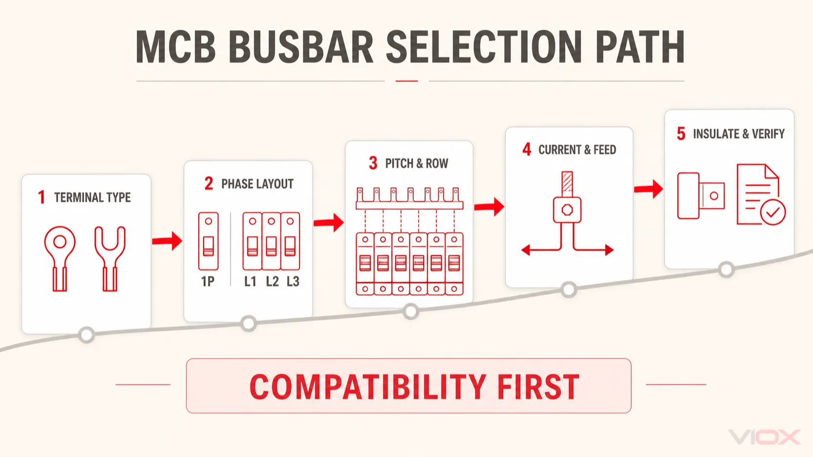
Bir MCB bara, commonly called a tarak bara, distributes one incoming supply across a row of miniature circuit breakers without separate jumper wires between every device. Select it in this order: match the breaker terminal, choose the phase and pole pattern, verify the tooth pitch and device layout, size the current path, check the declared voltage and assembly requirements, and specify the connector and insulation accessories.
The busbar is not universal simply because the breakers are DIN-rail mounted or 18 mm wide. Pin shape, fork width, terminal depth, phase sequence, neutral position, current rating, and the breaker series must all be compatible. If the teeth do not enter and clamp naturally, do not bend, grind, split, or force them.
For product evaluation, compare the VIOX MCB busbar range with the exact breaker series used in the panel.
MCB Busbar Selection in 60 Seconds
Use this table before choosing a catalog number or requesting a quotation.
| Seçim girdisi | What to specify | Neden önemli |
|---|---|---|
| Devre kesici terminali | Pin, fork, or series-specific connection | The wrong contact geometry can clamp poorly and overheat |
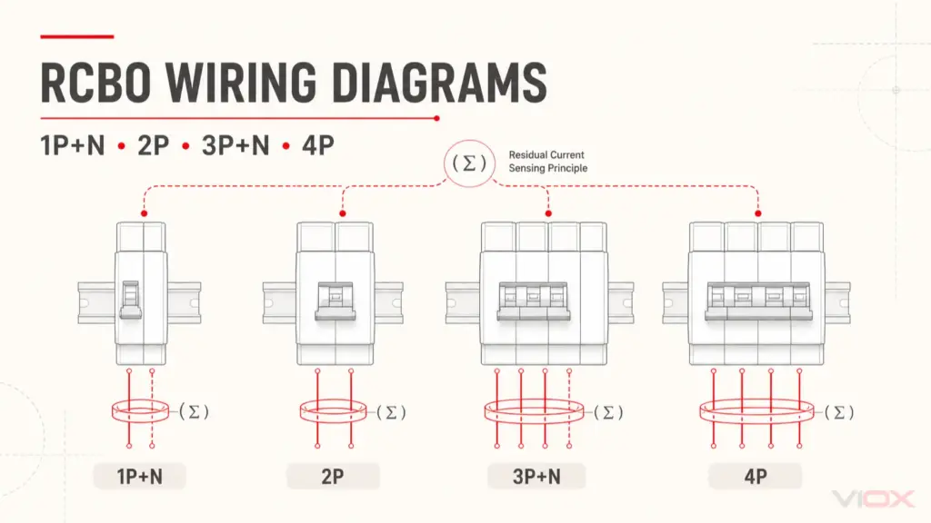
| Elektriksel yerleşim | 1P, 2P, 3P, 4P, 1P+N veya 3P+N | Determines the repeated phase and neutral tooth sequence |
| Device row | Exact MCB, RCCB, RCBO, isolator, or SPD series and order | Similar module widths do not guarantee aligned terminals |
| Hatve | Center-to-center tooth spacing and terminal position | Small pitch errors accumulate across a long breaker row |
| Mevcut yol | Design current, upstream protection, feed position, grouping, and enclosure temperature | Determines the required catalog rating and thermal margin |
| Voltage and insulation | Operational voltage, insulation data, end caps, and unused-tooth covers | Prevents exposed live copper and insulation mismatch |
| Uzunluk | Number of ways/modules, cut length, and spare positions | Controls tooth count and exposed-end treatment |
| Incoming connection | Cable size, connector type, entry direction, and feed position | The connector is part of the current path and may become the thermal bottleneck |
| Dokümantasyon | Busbar drawing, breaker compatibility, assembly design, and torque instructions | Physical fit alone does not establish a verified connection |
Seçim kuralı: compatibility comes first, electrical rating second, and installation verification third. A high-current busbar with the wrong tooth geometry remains the wrong busbar.
MCB Busbar, Comb Busbar, Link Bar, and Connector: Are They the Same?
Market terminology varies, so confirm the physical part instead of ordering from the name alone.
| Dönem | Usually refers to | Önemli sınır |
|---|---|---|
| MCB bara | Prefabricated conductor feeding multiple modular breakers | Broad product term; may use pins, forks, or a series-specific profile |
| Faz barası | Insulated bar with repeated teeth arranged like a comb | Common form of MCB busbar |
| MCB link bar / breaker link bar | May refer to a comb busbar or a shorter rigid linking conductor | Ask for a drawing; it is not a controlled universal synonym |
| Jumper bar | A rigid link between selected terminals or devices | May not distribute power across a complete breaker row |
| MCB bara bağlantı parçası | Accessory connecting the incoming cable or main device to the busbar | It is a feed component, not the comb busbar itself |
| Shorting link | A link intentionally shorting designated terminals in a specific circuit | Do not assume it means an MCB distribution busbar |
For a broader terminology overview, see Circuit Breaker Busbar Explained. If the decision is between individual conductors and a prefabricated bar, use the separate comb busbar vs jumper wire comparison.
Step 1: Match the Busbar to the Breaker Terminal
The first question is not the current rating. It is whether the busbar tooth can be correctly seated and clamped in the breaker terminal.
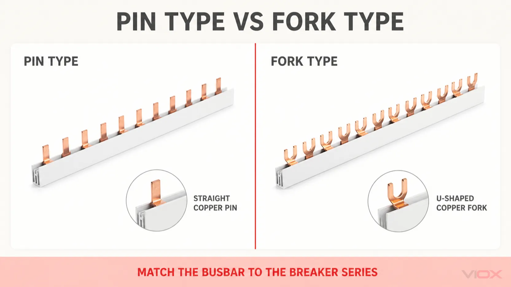
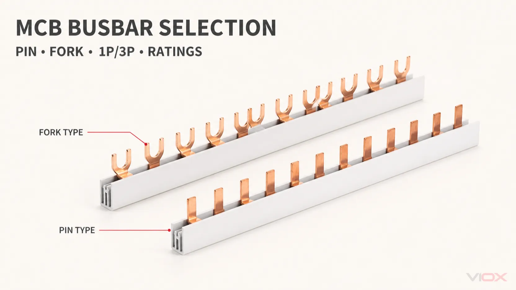
Pin type MCB busbar
A pin busbar has straight, narrow teeth that enter a compatible tunnel, cage, or dual terminal. Check:
- pin width, thickness, and insertion length;
- terminal opening and usable insertion depth;
- whether the cable and pin can share the terminal, if required;
- whether the busbar mounts at the top or bottom;
- the breaker manufacturer’s permitted tightening torque.
A pin connection is not automatically a no-torque push-in connection. Many breakers still use a screw-operated cage to clamp the inserted pin.
Fork type MCB busbar
A fork busbar has U-shaped teeth positioned around or beneath a compatible screw-clamp structure. Check:
- fork width and slot size, often described by a compatible M5 or M6 geometry;
- fork length and the available clamping surface;
- whether the fork is captured by the terminal clamp rather than floating beneath a screw head;
- insulation clearance around the terminal;
- whether the cable and fork arrangement is approved for that breaker series.
Pin and fork teeth are not interchangeable. The detailed differences are covered in Pin Tipi Bara ve Çatal Tipi Bara Karşılaştırması.
Series-specific terminals
Compact RCBOs, 1P+N breakers, dual-terminal devices, and mixed rows may use a dedicated busbar system. Do not infer compatibility from the front width of the device. Verify the manufacturer’s dimensional drawing or documented accessory relationship.
Step 2: Select the Phase and Pole Pattern
The busbar must reproduce the panel’s electrical distribution pattern, not merely span the correct number of modules.
| Busbar pattern | Tipik işlev | Critical check |
|---|---|---|
| 1P / 1L | One line conductor feeds a row of single-pole breakers | Common pitch, tooth count, and total current path |
| 2P / 2L | Two conductors repeat across compatible devices | Confirm whether the application is two-line, split-phase, or another defined arrangement |
| 3P / 3L | L1-L2-L3 repeats across the row | Phase sequence and breaker grouping must match the panel drawing |
| 4P / 4L | Four conductors repeat across compatible four-pole positions | Confirm whether the fourth conductor is neutral and how it is switched or protected |
| 1P+N | Line and neutral positions serve compact 1P+N devices | Neutral tooth location and 9 mm/18 mm device geometry may differ |
| 3P+N | Three phases plus a defined neutral position | Do not treat it as automatically interchangeable with every 4P system |
A 3 phase MCB busbar is not simply a longer single-phase bar. Its teeth distribute L1, L2, and L3 in a repeated sequence. Before cutting it, map each tooth to the intended breaker pole and identify every unused live position.
Neutral terminology also requires care. A 3P+N device may switch the neutral without providing the same overcurrent function as its phase poles, while another four-pole device may use a different terminal sequence. The busbar pattern must match the exact device series and the approved circuit design.
Step 3: Verify Pitch Across the Complete Device Row
Pitch is the center-to-center distance between adjacent busbar teeth. Many modular breaker systems use approximately 18 mm per module, but module width alone does not establish compatibility.
Check the complete row for:
- tooth pitch and accumulated alignment;
- terminal height and depth;
- 9 mm compact devices or half-module offsets;
- RCCBs, RCBOs, isolators, or SPDs mixed with MCBs;
- auxiliary contacts or blank modules that interrupt the sequence;
- top-feed or bottom-feed terminal orientation;
- phase and neutral tooth positions.
A small dimensional mismatch may appear acceptable at the first breaker and become severe by the twelfth module. The correct response is to change the busbar, device arrangement, or approved adapter, not to pull the devices sideways or deform the copper teeth.
For mixed-brand panels, follow the verification sequence in the MCB Bara Uyumluluk Kılavuzu.
Step 4: Select Current Rating From the Actual Current Path
Do not size an MCB comb busbar by adding every outgoing breaker handle rating. Ten 16 A branch breakers do not prove that 160 A flows continuously through the busbar, but assumed load diversity does not justify an undersized bar either.
Establish the current path from:
- the incoming supply and upstream protective device;
- the expected continuous and simultaneous load;
- the busbar feed position;
- the current carried by each section of the bar;
- enclosure temperature and device grouping;
- the catalog conditions attached to the declared current rating;
- the applicable assembly verification.
End feed versus center feed
With end feeding, the section nearest the incoming connector carries the combined downstream current. With a documented center-feed arrangement, current can divide in two directions. This may reduce the current carried by each side, but it does not automatically double the permissible rating. Use only the feed configurations and limits published for the selected system.
| Feed arrangement | Mevcut yol | Seçim etkisi |
|---|---|---|
| Uçtan besleme | Combined current initially passes through one end section | Check the first teeth, incoming connector, and upstream section carefully |
| Merkezi besleme | Current divides toward the left and right branches | Requires a compatible feed point and documented current limits |
| Çoklu besleme noktaları | Several sources or connectors energize the bar | Use only as part of an engineered assembly; unintended parallel paths are possible |
Catalog rating is not an assembly rating
A manufacturer’s current rating applies under stated product and installation conditions. Inside a populated distribution board, breaker heat, conductor routing, enclosure ventilation, ambient temperature, grouping, and connection resistance influence the final temperature rise.
IEC 61439-1 provides general rules for low-voltage assemblies and must be used with the applicable assembly part. IEC 61439-2, for example, covers power switchgear and controlgear assemblies within its stated scope. These standards address the assembly, not a claim that any standalone comb busbar is universally suitable once its printed ampere value exceeds the feeder current.
Step 5: Check Voltage, Insulation, and Short-Circuit Conditions
Verify the busbar’s declared operational voltage and insulation information against the panel system. After a cut-to-length busbar is installed, no sawn copper end or unused energized tooth should remain accessible.
Specify:
- rated operational voltage and any stated insulation voltage;
- insulated copper body and finger-protection provisions;
- end caps for every cut end;
- covers for unused live teeth;
- required clearances around adjacent terminals and accessories;
- insulation material and temperature limitations stated by the manufacturer.
Short-circuit performance must be evaluated as part of the defined combination of busbar, incoming device, outgoing devices, connectors, conductors, support arrangement, and enclosure. A busbar cross-section by itself does not prove the short-circuit withstand of the completed assembly. Request the manufacturer’s applicable configuration data or assembly verification evidence instead of converting a catalog current rating into an unsupported fault-current claim.
Step 6: Specify Length, Tooth Count, Connector, and Accessories
The ordering specification should describe the complete connection system, not only the copper bar.
Length and cutting
Confirm the number of modules, number of usable ways, overall length, permitted cutting method, and spare positions. A cuttable busbar must be cut at an approved location, deburred without damaging the remaining insulation, cleaned, and fitted with the correct end cap. See Tarak Bara Doğru Şekilde Nasıl Kesilir ve Yalıtılır for the separate installation procedure.
Incoming connector
An MCB busbar connector transfers the feeder current into the comb busbar. Match its:
- conductor size range and conductor material;
- current and voltage data;
- pin or fork interface;
- kablo giriş yönü;
- position relative to the breaker row;
- insulation cover and tightening instructions.
The connector can become the hottest point even when the busbar conductor is adequately sized. If discoloration or abnormal heating is already present, use the MCB busbar overheating guide rather than increasing the busbar rating without diagnosing the connection.
VIOX MCB Busbar Catalog Reference
The following table shows how dimensional inputs translate into a product-family shortlist. It is based on current VIOX catalog working data and is provided for initial comparison only.
| VIOX catalog family | Layouts | Copper cross-section options | Tooth pitch / distance | Kontak geometrisi | Standard length examples | Reference current options |
|---|---|---|---|---|---|---|
| P-1L / P-2L / P-3L | 1-, 2-, and 3-line | 8, 10, 13, 16 mm² | 17.8 mm | 4 mm pin width; 11.5 mm pin length | 210 mm / 12 modules; 1000 mm / 54 modules; 1016 mm / 56-57 modules | 50, 63, 70, 80 A |
| P-4L | 4 kutuplu | 8, 10, 13, 16 mm² | 17.8 mm | 4 mm pin width; 11.5 mm pin length | 210 mm / 12 modules; 1016 mm / 56 modules | 50, 63, 70, 80 A |
| F-1L / F-2L / F-3L | 1-, 2-, and 3-line | 8, 10, 13, 16 mm² | 17.8 mm | M6 fork: 12 mm width and length | 210 mm / 12 modules; 1000 mm / 54 modules; 1016 mm / 56-57 modules | 50, 63, 70, 80 A |
| F-3L M5 | 3-line | 8, 10, 13, 16 mm² | 17.8 mm | M5 fork: 11 mm width; 11.5 mm length | 210 mm / 12 modules; 1000 mm / 54 modules; 1016 mm / 57 modules | 50, 63, 70, 80 A |
| P-1+N | 1P+N | 8, 10, 13, 16 mm² | 9 mm | 4 mm pin width; 11.5 mm pin length | 210 mm / 24 modules; 1000 mm / 108 modules | 50, 63, 70, 80 A |
Yalnızca katalog değerleri: Confirm the current VIOX datasheet, dimensional drawing, breaker compatibility, rating conditions, and model-specific evidence before specification. These entries do not establish the temperature rise or short-circuit performance of a completed distribution board.
Three Example Specifications
These examples show how to describe the requirement; they are not universal product selections.
Example 1: Single-phase row of 1P MCBs
Specify a 1-line insulated comb busbar, the exact compatible pin or fork profile, tooth pitch matching the selected MCB series, sufficient ways for the populated row and planned spare positions, a declared current rating suitable for the feeder and thermal design, plus an incoming connector, unused-tooth covers, and end caps.
Example 2: Three-phase row of single-pole outgoing circuits
Specify a 3-line L1-L2-L3 repeating busbar, map every tooth to the panel schedule, confirm the grouping of outgoing breakers, verify the feed position and current carried by each section, and cover every unused energized tooth. Do not cut before confirming the final phase sequence.
Example 3: Mixed MCB and RCBO row
List each device by manufacturer and series in installation order. Record module width, terminal position, neutral arrangement, and permitted busbar accessory. If one device interrupts the pitch or uses a different terminal level, use a documented adapter, separate approved busbar section, or a revised panel layout rather than forcing one continuous bar across the row.
Compatibility Verification Before Energizing
Use this pass/fail sequence after installation:
| Kontrol | Geçme koşulu |
|---|---|
| Product identity | Busbar and connector catalog numbers match the approved panel documentation |
| Terminal geometry | Every tooth is fully inserted and captured by the intended clamp |
| Alignment | Devices sit naturally on the DIN rail without side loading or distorted teeth |
| Phase mapping | L1, L2, L3, and N positions match the schematic and panel schedule |
| İzolasyon | Cut ends and unused live teeth have the correct covers |
| Incoming feed | Cable size, connector, and feed position match the selected system |
| Tightening | All terminals follow the device manufacturer’s torque instructions |
| Electrical tests | Required continuity, insulation, polarity, and assembly checks are complete |
| Dokümantasyon | Final device order and busbar configuration are recorded for maintenance |
De-energize, isolate, and verify absence of voltage before touching or adjusting a busbar. Installation and verification must be performed by qualified personnel under the applicable local rules and manufacturer instructions.
MCB Busbar RFQ Checklist
Send the following information when requesting a quotation:
- sistem gerilimi ve frekansı;
- single-phase or three-phase layout;
- required pattern: 1P, 2P, 3P, 4P, 1P+N, or 3P+N;
- breaker, RCCB, and RCBO manufacturer and exact series;
- pin, M5 fork, M6 fork, or dimensional drawing;
- pitch, tooth width, tooth length, and terminal position;
- number and order of devices;
- design current, upstream protection, and feed position;
- required length or module count;
- incoming cable size and entry direction;
- end caps, tooth covers, and connectors;
- target market and required product or assembly documentation.
Providing a breaker terminal photograph and dimensioned panel layout can prevent a costly compatibility error, but photographs should supplement rather than replace dimensional and manufacturer data.
Sıkça Sorulan Sorular
What is an MCB link bar?
An MCB link bar commonly means a rigid conductor linking several miniature circuit breakers. In some markets it refers to a full comb busbar; in others it may mean a shorter linking piece. Confirm the drawing, tooth pattern, length, and rating rather than ordering by the term alone.
Is an MCB busbar connector the same as a comb busbar?
No. The comb busbar distributes power across multiple breakers. The connector transfers the incoming cable or main-device output into that busbar. Both must be correctly rated and geometrically compatible.
Can any 18 mm busbar fit any 18 mm MCB?
No. The module pitch may match while terminal depth, pin thickness, fork width, clamp design, neutral position, or insulation clearance differs. Match the busbar to the exact breaker series or documented compatibility data.
What is the difference between a 1 phase and 3 phase MCB busbar?
A single-phase busbar generally repeats one line connection across the breaker row. A three-phase busbar repeats L1, L2, and L3 in sequence. The three-phase tooth pattern must match the breaker grouping and panel schedule.
Can an MCB busbar be cut to length?
Only if the selected product is designed to be cut. Follow its cutting instructions, remove burrs without damaging insulation, and install the specified end cap. Recheck phase sequencing before cutting a multiphase bar.
How do I choose the MCB busbar current rating?
Start with the incoming supply, upstream protection, continuous and simultaneous load, feed location, section currents, enclosure temperature, grouping, and the manufacturer’s rating conditions. Do not use only the sum of outgoing breaker handle ratings.
MCB baraları markalar arasında değiştirilebilir mi?
Not automatically. DIN-rail mounting and similar front dimensions do not prove terminal compatibility. Use the matched accessory system or documented dimensional and application evidence.
Nihai Seçim Kuralı
Choose an MCB busbar by converting the panel design into a complete specification: terminal geometry, phase pattern, pitch, device sequence, current path, feed position, insulation, connector, and documentation. The correct bar should seat without modification, preserve the intended phase sequence, remain insulated after cutting, and belong to a verified device-and-assembly configuration.
To request a model shortlist, provide VIOX with the breaker series, terminal drawing, phase pattern, module count, design current, incoming conductor size, and target-market documentation requirements.