
Selecting the right circuit breaker pole configuration is one of the most critical—and frequently misunderstood—decisions in electrical system design. The difference between a single-pole (1P), single-pole with neutral (1P+N), and double-pole (2P) breaker determines not just whether your system works, but whether it protects equipment and personnel safely. Using the wrong configuration can leave a conductor energized even when the breaker is switched off, creating silent shock hazards. It can also violate electrical codes, compromise warranty coverage, and expose facility managers to serious liability. This guide cuts through the confusion with a practical framework for selecting the right pole configuration based on your specific electrical system, load characteristics, and regional standards.
What Are Circuit Breaker Poles?
A pole in a circuit breaker refers to an independent switching mechanism that controls one conductor (wire). Think of it as an individual switch that can interrupt electrical current; in multi-pole breakers, these switches are mechanically linked so they trip together under fault conditions. The number of poles directly determines which types of electrical systems the breaker can safely protect and whether certain conductors remain energized during a fault or maintenance shutdown.
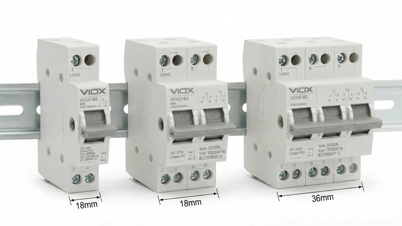
Each pole occupies approximately 18mm of space on a DIN rail and contains:
- A thermal element (bimetallic strip) for overload protection
- A magnetic element (coil) for short-circuit detection
- Contacts that physically separate to interrupt current
- A mechanical linkage connecting all poles in the breaker unit
The critical distinction is that more poles don’t necessarily mean more protection—they mean different protection strategies applied to different conductors. A 1P breaker protects one phase conductor; a 1P+N protects one phase conductor while providing neutral switching (but typically not protection); and a 2P breaker protects both phase conductors equally.
1P (Single Pole) Circuit Breaker: The Basics
Single-pole breakers are the workhorse of residential electrical systems, protecting individual 120V circuits in North American installations and 230V single-phase circuits in IEC-standard regions. They are the smallest and most economical option, occupying a single DIN rail module.
Technical Specifications
- Voltage Rating: 120V AC (US) or 230V AC (IEC)
- Current Ratings: 6A to 63A (most common: 15A, 20A, 32A)
- Module Width: 1 module (18mm)
- Breaking Capacity: 6kA to 10kA (IEC 60898-1)
- Number of Protected Conductors: 1 (phase wire only)
How 1P Protection Works
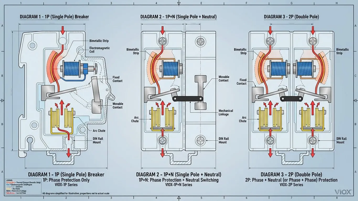
The 1P breaker monitors current flowing through the phase (hot) wire only. The neutral wire connects directly to a common neutral bus in the panel and remains connected even when the breaker trips. This creates a fundamental limitation: if a fault makes the neutral wire “live” elsewhere in the system, that dangerous voltage can remain present even though your local breaker is switched off.
When to Use 1P
- Standard residential lighting circuits
- General-purpose outlets (up to the panel’s safe capacity)
- Circuits for small appliances (dishwashers, garbage disposals, microwaves)
- In TN-S earthing systems where the neutral is reliably bonded to earth
- Cost is a primary constraint and system safety permits no neutral switching
Critical Limitation
⚠️ A 1P breaker cannot protect against faults that develop on the neutral conductor itself. If a neutral wire becomes damaged and carries return current unexpectedly, the 1P breaker will not detect this overload. This is why modern electrical codes increasingly mandate neutral monitoring in systems where harmonics or unbalanced loads are possible.
1P+N (Single Pole + Neutral): The Modern Standard
This is where the confusion begins—and where understanding the IEC standard becomes essential for international projects. The 1P+N breaker (also called DPN in older literature) switches both the phase and neutral conductors simultaneously but provides overcurrent protection only to the phase.
The Critical Distinction: Switching vs. Protection
This is the single most misunderstood aspect of 1P+N technology:
| Function | 1P | 1P+N | 2P |
|---|---|---|---|
| Switches Phase | Yes | Yes | Yes |
| Switches Neutral | No | Yes | Yes |
| Protects Phase | Yes | Yes | Yes |
| Protects Neutral | No | No | Yes |
The 1P+N breaker switches (disconnects) the neutral for maintenance isolation but does not include a thermal-magnetic sensor monitoring the neutral wire. This distinction has profound implications:
Scenario: Why Neutral Switching Matters
During maintenance, an electrician works on a 1P+N protected circuit. With a 1P breaker, flipping the switch leaves the neutral conductor still connected to the supply. If another circuit’s neutral fault inadvertently puts voltage on this neutral, the electrician touching the “switched off” neutral could receive a lethal shock. With a 1P+N breaker, both phase and neutral are physically disconnected, preventing this hazard entirely.
When Neutral Protection Becomes Mandatory
While 1P+N provides switching, neutral protection (monitoring) becomes essential in specific high-risk scenarios:
1. Reduced Neutral Cross-Section
Per IEC 60364-4-43, if the neutral conductor’s cross-sectional area is smaller than the phase conductor, protection must monitor the neutral. Smaller conductors overheat faster, and phase-only monitoring cannot detect this overload.
Example: A 10mm² phase wire with a 4mm² neutral wire. If return current exceeds what the smaller neutral can safely carry, without neutral monitoring it will overheat undetected. A 2P or true neutral-protected 1P+N breaker detects this.
2. Harmonic Currents in Modern Facilities
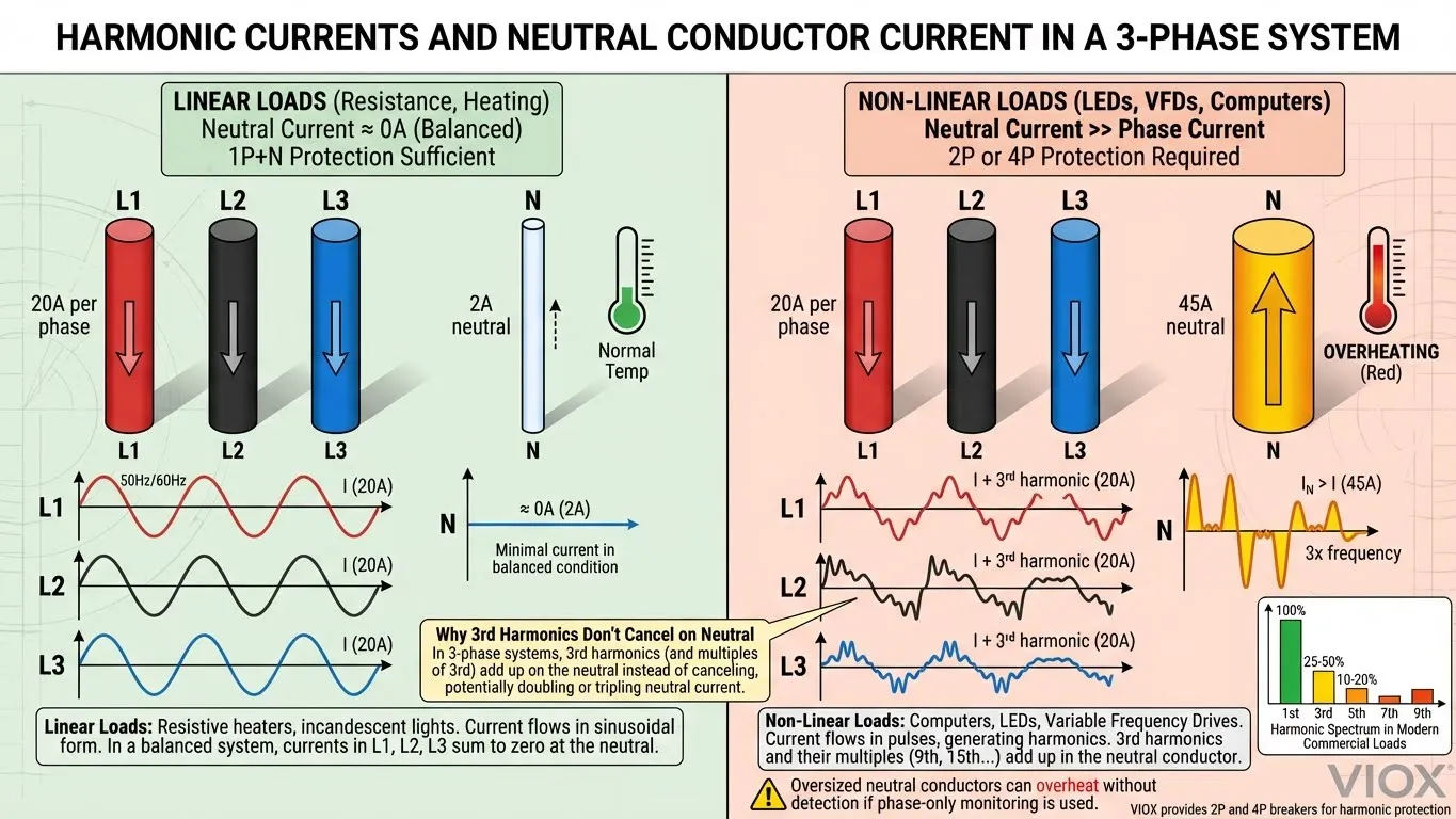
In office buildings, data centers, and commercial kitchens with LED lighting, variable frequency drives, and computer equipment, non-linear loads generate harmonic currents. The 3rd harmonic (and other odd harmonics) does not cancel in the neutral wire as it does in the phase conductors. If harmonic content exceeds 15–33% of phase current, the neutral wire can actually carry more current than the phase wires.
Real-World Example: A commercial kitchen with 20 induction cooktops (highly non-linear load). The 3P+N feeder’s neutral might carry 150A while each phase carries only 100A. Standard phase monitoring misses the overheated neutral conductor. Modern codes now require 4P protection in such scenarios.
3. TT and IT Earthing Systems
The earthing system fundamentally changes neutral protection requirements:
- TN-S System (common in Europe): Neutral is reliably bonded to earth at the transformer. A 1P+N is typically sufficient for isolation during maintenance.
- TT System: Neutral is not bonded to the facility’s earth, so it cannot be assumed “safe.” Full 2P protection becomes advisable.
- IT System: Neutral is isolated from earth. A 2P breaker is mandatory because neutral-to-earth faults are common and create dangerous fault currents in the neutral wire.
1P+N Advantages Over 1P
- ✓ Complete isolation of the circuit during maintenance (neutral is switched)
- ✓ Prevents shock hazard from neutral-to-earth faults on downstream circuits
- ✓ Meets European and IEC standards for safe maintenance practices
- ✓ Same DIN rail width as 1P (18mm), so cost increase is minimal
- ✓ Increasingly mandatory in modern commercial installations
When 1P+N Insufficient
- Harmonic currents exceed 15% of phase current (use 2P or protective neutral)
- Neutral conductor is undersized relative to phase
- IT earthing system (must use 2P)
- High-reliability applications where full conductor monitoring is required
2P (Double Pole) Circuit Breaker: Full Protection
The 2P breaker provides symmetric protection on both conductors—typically both phase wires in a 240V single-phase circuit, or one phase and one neutral in specialized applications. Each pole contains independent thermal and magnetic elements.
Technical Specifications
- Voltage Rating: 240V AC (US) or 230V AC (can be 2-phase or phase+neutral in IEC)
- Current Ratings: 20A to 100A typical for residential; up to 1600A+ for industrial
- Module Width: 2 modules (36mm)
- Breaking Capacity: 10kA to 100kA depending on series
- Number of Protected Conductors: 2 (both phase wires, or phase+neutral)
How 2P Protection Works
In a 240V US residential installation, the 2P breaker connects to two separate phase legs of the main service (L1 and L2), each 120V relative to neutral. The breaker monitors both conductors for overcurrent:
- If either leg overloads, both poles trip simultaneously (mechanical linkage)
- Both conductors are disconnected completely, ensuring no voltage remains on the circuit
In IEC applications where a 2P might protect phase+neutral, both conductors receive identical monitoring and switching.
Typical Applications
- 240V US residential: Electric ranges, dryers, water heaters, air conditioning units, EV chargers
- Industrial 2-phase: Step-down transformers, specialized motor applications
- Main disconnects: Often use 2P or larger for complete system isolation
- High-reliability circuits: Where symmetric protection is preferred
2P vs. 1P+N for Neutral Protection
A common question: “Should I use 2P instead of 1P+N for better neutral protection?”
The answer depends on your earthing system and load type:
- Use 1P+N in TN-S systems with linear loads (lighting, heating). It provides required switching at minimal cost.
- Use 2P (or 4P in 3-phase) when harmonics exist, unbalanced loads are present, or you operate under IT earthing.
- Use 2P as main feeder protection regardless, to ensure complete isolation during maintenance.
Comprehensive Comparison Table
| Feature | 1P | 1P+N | 2P |
|---|---|---|---|
| Phase Protection | Yes | Yes | Yes |
| Neutral Protection | No | No | Yes |
| Neutral Switching | No | Yes | Yes |
| Typical Voltage | 120V or 230V | 230V | 240V (US) or 2-phase IEC |
| Module Width | 1 (18mm) | 1 (18mm) | 2 (36mm) |
| Breaking Capacity | 6-10kA | 6-10kA | 10-100kA+ |
| Cost Range | €3-8 | €4-10 | €8-25 |
| Suitable for Harmonics | ⚠️ Limited | ⚠️ Limited | ✓ Yes (with 4P for 3-phase) |
| TN-S System | Acceptable | Preferred | Over-specified |
| TT System | Not recommended | Acceptable | Recommended |
| IT System | Not suitable | Not suitable | ✓ Required |
Selection Framework: How to Choose
Selecting the right pole configuration requires evaluating four factors:

Step 1: Determine Your System Type
- Single-phase 120V/240V residential (North America): Choose between 1P (lighting) and 2P (high-power appliances)
- Single-phase 230V residential (Europe/IEC): Choose 1P (lighting, small loads) or 1P+N (all circuits)
- Three-phase systems: Consider 3P, 3P+N, or 4P based on neutral current risk (covered in companion articles)
Step 2: Identify Earthing System & Maintenance Requirements
- TN-S: 1P acceptable for lighting; 1P+N for general circuits
- TT: 1P+N required as minimum; 2P recommended for important circuits
- IT: 2P mandatory for all circuits
Step 3: Assess Load Characteristics
- Linear loads (resistive heating, incandescent lighting): 1P or 1P+N sufficient
- Mixed loads with electronics (offices, kitchens): Check harmonic content
- If harmonics exceed 15%, upgrade to 2P or 4P (if 3-phase)
- Motor circuits: Typically use 2P or dedicated motor protection breakers
Step 4: Verify Code Requirements
- EU (IEC): Article 411.3.2.2 often mandates neutral switching via 1P+N or higher
- US (NEC): Multi-wire branch circuits require simultaneous disconnection (use 2P for 240V)
- Check local amendments: Some jurisdictions impose stricter requirements
Common Selection Mistakes to Avoid
⚠️ Mistake 1: Using 1P for 240V circuits
This is the most dangerous error. A 1P breaker on a 240V circuit protects only one phase leg, leaving the other conductor energized even when “switched off.” This creates a fatal shock hazard and violates electrical code.
⚠️ Mistake 2: Assuming 1P+N Provides Neutral Protection
The “N” means switching, not protection. In harmonic-rich environments, neglecting true neutral protection can allow the neutral to overheat undetected.
⚠️ Mistake 3: Over-specifying 2P in TN-S Systems
While not dangerous, using 2P where 1P+N suffices wastes panel space and cost. However, using 2P for main feeders and high-reliability circuits remains best practice.
⚠️ Mistake 4: Ignoring Future Harmonics
A circuit installed for resistive loads today may be repurposed for LED lighting or VFDs tomorrow. Specifying neutral monitoring upfront prevents expensive retrofits.
Frequently Asked Questions
Q: Can I upgrade a 1P circuit to 1P+N by installing a separate neutral disconnect switch?
A: No. The breaker and neutral switch are separate devices with different trip characteristics. A true 1P+N breaker is specifically engineered to coordinate these functions. Adding a separate switch creates coordination problems and confusion during maintenance.
Q: In the US, why do some 240V circuits use 2P while others use two separate 1P breakers connected together?
A: A 2P breaker ensures simultaneous disconnection via a single mechanical linkage. Two separate 1P breakers might not trip exactly simultaneously under fault conditions, creating momentary phase-to-phase faults. NEC requires simultaneous disconnection, making 2P the proper choice.
Q: Does VIOX offer 1P+N breakers for EU systems?
A: Yes. VIOX’s VM-series MCBs include both 1P and 1P+N configurations compliant with IEC 60898-1, with neutral protection options available in 2P variants for high-harmonics applications.
Q: If I have a TN-C system (neutral and earth combined as PEN conductor), can I use a 1P+N breaker?
A: Absolutely not. TN-C systems prohibit breaking the PEN conductor at any point. Breaking it would remove the safety ground from downstream circuits. Use only 1P breakers in TN-C systems.
Q: What harmonics percentage triggers the need for neutral protection?
A: Per IEEE and IEC guidelines, neutral protection becomes strongly advisable when 3rd harmonic content exceeds 15% of fundamental phase current, and mandatory above 33%. Modern LED and VFD installations routinely generate 20–50% harmonic content.
Key Takeaways
✓ 1P breakers protect one conductor only and are suitable for linear-load residential circuits in TN-S systems where neutral isolation is not required.
✓ 1P+N breakers add neutral switching for maintenance safety and are the modern EU/IEC standard for all general circuits, though they do not provide neutral protection.
✓ 2P breakers provide full protection on both conductors and are essential for 240V circuits, IT earthing systems, and any application where harmonics or unbalanced loads exist.
✓ Earthing system (TN-S, TT, IT) and load harmonic content are the two dominant factors determining pole selection—not voltage alone.
✓ When in doubt, upgrade to the next protection level (1P → 1P+N → 2P). The cost difference is minimal, but the safety and code-compliance gains are substantial.
Related Articles
- Types of Circuit Breakers: The Complete Selection Guide
- How Circuit Breaker Poles Affect Voltage & Current Protection
- Where to Use SP, TP, TPN and 4P Circuit Breakers
- 2-Pole vs 3-Pole Breaker: Complete Guide
- What is a Miniature Circuit Breaker (MCB)
- Circuit Breaker Ratings: ICU, ICS, ICW, ICM Explained
