
Most busbar insulator failures in the field are not caused by the wrong voltage rating. They are caused by selecting the part in isolation — without considering the busbar layout, the mechanical forces acting on the support, the operating environment, or the actual mounting constraints of the assembly.
To choose the right busbar insulator, you need to treat it as what it actually is: a structural and electrical component that must satisfy two jobs simultaneously. It must maintain reliable insulation between live conductors and grounded structures, and it must physically support the busbar under static load, thermal cycling, vibration, and fault conditions. If either job is underestimated, the insulator will eventually fail — even when the catalog specification looks perfectly acceptable on paper.
This guide walks through the complete selection process, from system voltage to final assembly review, so you can make a confident, application-correct choice the first time.
Key Takeaways
- The right busbar insulator must satisfy both electrical insulation duty and mechanical support duty — not one or the other.
- Voltage rating alone is never sufficient for selection. Creepage, clearance, mechanical load, thermal conditions, and contamination all play a role.
- Mounting style, busbar weight, short-circuit force, operating temperature, environmental exposure, and available panel space must all be evaluated before choosing a part number.
- Material selection should be driven by the application environment, not by habit or past precedent.
- Indoor panel insulators and outdoor or polluted-environment insulators require fundamentally different selection logic.
- A good selection process evaluates the insulator together with the complete busbar layout — never as an isolated catalog line item.
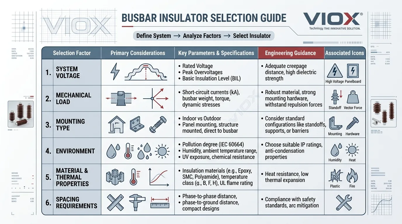
Quick Busbar Insulator Selection Table
Use this table as an at-a-glance reference before diving into the detailed guidance below.
| Selection Factor | What to Check | Why It Matters |
|---|---|---|
| System voltage | Rated insulation voltage, impulse withstand level, and working voltage | Defines the baseline electrical duty the insulator must handle |
| Busbar layout | Busbar cross-section, orientation (flat or edgewise), phase spacing, and support span | Determines the support geometry, mechanical loading, and spacing constraints |
| Mechanical load | Static busbar weight, vibration, and electrodynamic fault stress | The insulator must carry the busbar safely under both normal and fault conditions |
| Insulator type | Support, standoff, post, bushing-style, or application-specific form | Different shapes solve different mounting and routing problems |
| Material | BMC, SMC, epoxy, porcelain, or polymer composite | Affects tracking resistance, heat tolerance, mechanical strength, and long-term durability |
| Environment | Indoor, outdoor, humidity level, pollution degree, UV exposure, chemical atmosphere | Strongly affects insulation performance and service life |
| Panel space | Mounting height, minimum clearance, creepage path length, and service access | Determines whether the insulator can be safely installed and maintained |
| Hardware fit | Thread size, stud length, mounting base footprint, and interface dimensions | Prevents installation mismatch, weak assembly, and project delays |
Start with the Application, Not the Part Number
The most reliable way to choose a busbar insulator is to begin with the application context — not the supplier catalog.
Before looking at any product data, answer these questions:
- What type of equipment is this for? A low-voltage distribution panel, a motor control center, a switchboard, an inverter assembly, or a power distribution unit each present different constraints.
- What is the installation environment? Indoor, outdoor, semi-enclosed, or within a sealed IP-rated enclosure? A clean control room and a coastal industrial plant are worlds apart.
- What is the insulator’s primary role? Supporting a straight horizontal busbar run, holding a compact vertical connection point, or providing insulated passage through a grounded barrier?
- Where does the difficulty lie? Is the application electrically demanding (high voltage, tight spacing, contaminated atmosphere), mechanically demanding (heavy busbars, long spans, high fault levels), or both?
Without this context, selecting by catalog image or part number alone almost always leads to one of three outcomes: over-specification that wastes money, under-specification that creates risk, or a mismatch that forces avoidable redesign during assembly.
1. Confirm the System Voltage and Insulation Duty
The insulator must be fully suitable for the electrical stress of the system — and that means looking beyond the nominal voltage printed on the single-line diagram.
A thorough voltage and insulation review should cover:
- Phase-to-phase and phase-to-earth voltage levels. In a 690 V three-phase system, the phase-to-earth voltage differs from the line voltage. Both matter for insulation coordination.
- Rated insulation voltage (Ui) and impulse withstand voltage (Uimp). These define the insulation performance required by the relevant standard (e.g., IEC 61439 for low-voltage switchgear assemblies).
- Required insulation margin. The working voltage should sit comfortably below the insulator’s rated capability, not right at the edge.
- Separation distance requirements within the assembly. Minimum clearance and creepage distances dictated by the standard, pollution degree, and overvoltage category must be achievable with the chosen insulator geometry.
- Contamination and humidity risk along the busbar path. In environments with conductive dust or high humidity, effective creepage distances are reduced. The insulator must compensate.
In practical panel design, the busbar insulator is one element of the overall insulation coordination system. Its rated voltage, physical height, and surface profile must support the required creepage, clearance, and physical separation strategy of the entire assembly.
A common mistake is checking the voltage at a broad level — “it’s rated for 1000 V, and our system is 400 V, so it’s fine” — without verifying that the insulator’s geometry actually delivers the needed creepage and clearance distances once installed in the real busbar arrangement.
2. Check the Mechanical Duty, Not Just the Insulation
This is where many busbar insulator selections go wrong.
Engineers tend to focus on dielectric performance because the word “insulator” naturally draws attention to electrical properties. But a busbar insulator is also a structural support. It physically holds the conductor in position. That means the part must withstand every mechanical force the busbar system will experience over its service life:
- Dead weight of the busbar. A 60 × 10 mm copper busbar weighs approximately 5.3 kg per meter. A three-phase stack with multiple bars per phase can impose substantial static load on each support point.
- Mounting and tightening stress. Over-torquing a fastener on a brittle insulator can crack the body during installation — before the system ever carries current.
- Vibration. Panels mounted on ships, near rotating machinery, or in seismic zones experience ongoing dynamic stress that can fatigue insulator materials and loosen hardware over time.
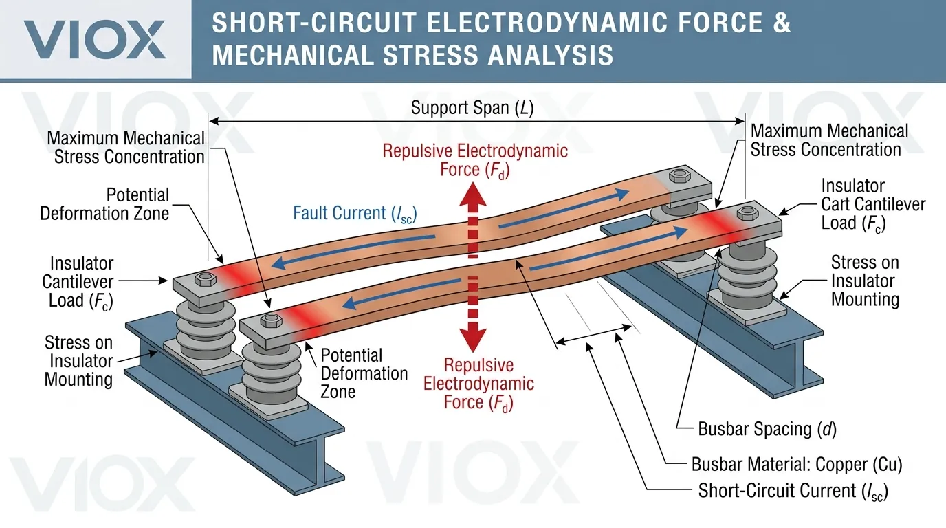
- Electrodynamic force during short-circuit events. This is often the most underestimated factor. A 50 kA fault on closely spaced busbars can generate peak forces of several thousand newtons per meter. The insulators must absorb this without cracking, displacing the busbar, or losing mechanical integrity.
- Thermal expansion and contraction. Copper busbars expand approximately 0.017 mm per meter per degree Celsius. Over a long run with significant temperature cycling, this expansion creates lateral forces on fixed support points.
In many real-world failure investigations, the insulator’s dielectric performance was never the issue. The part cracked, shifted, or lost its clamping integrity because the mechanical duty was underestimated or simply not evaluated during selection.
Questions to ask before selecting
- How long is the unsupported busbar span between adjacent insulators?
- How heavy is the conductor cross-section, and how many bars are stacked?
- Is the panel or enclosure subject to vibration, transportation shock, or seismic requirements?
- What is the prospective fault current, and what electrodynamic forces will the busbar support structure experience?
- Is the support point located near a joint, a bend, a tap-off, or a heavily loaded connection where forces concentrate?
3. Choose the Right Busbar Insulator Type
Different insulator forms exist because different mounting and routing problems exist. Selecting the wrong form factor — even with the right material and voltage rating — can create assembly difficulties or compromise performance.
Support or standoff insulators
These are the most widely used type in low-voltage busbar assemblies. A standoff insulator elevates the busbar above the mounting plate, DIN rail, or structural frame while providing electrical isolation between the live conductor and grounded metalwork.
They are typically cylindrical or hexagonal in shape, with threaded inserts or through-studs at both ends for secure fastening.
Best fit:
- Switchboards and panelboards
- Busbar trunking and support structures
- Compact distribution assemblies
- General-purpose industrial power panels
Post-style insulators
Post insulators provide a more defined vertical support form with greater mechanical rigidity. They are often taller and more robust than standard standoff types, making them suitable for applications where the busbar must be held firmly at a specific height with minimal deflection.
Best fit:
- Rigid busbar support points in medium- and low-voltage switchgear
- Busbar structures that require precise positioning
- Applications with higher mechanical load or longer support spans
Bushing-style or pass-through insulation forms
These are used when a busbar or conductor must pass through a grounded barrier — such as an enclosure wall, a compartment partition, or a bulkhead — while maintaining full electrical isolation. The insulator simultaneously provides insulation and a sealed or semi-sealed penetration.
Best fit:
- Barrier crossings between switchgear compartments
- Enclosure wall penetration points
- Transformer and generator terminal connections
- Specialized distribution and protection equipment
Custom or application-specific support forms
Some applications cannot be served by standard catalog shapes. These situations call for molded insulators designed to specific geometry, encapsulated support assemblies, or multi-function insulating structures that integrate support, separation, and routing in one part.
Best fit:
- OEM equipment with fixed internal architecture
- High-density custom panels where standard shapes don’t fit
- Products with proprietary busbar arrangements
- Applications requiring integrated insulation and structural functions
4. Select the Right Material
Material selection should follow the application requirements — not past habit or whatever the last project happened to use.
Each insulator material brings a different balance of electrical, thermal, and mechanical properties. Understanding these trade-offs is essential for making the right choice.
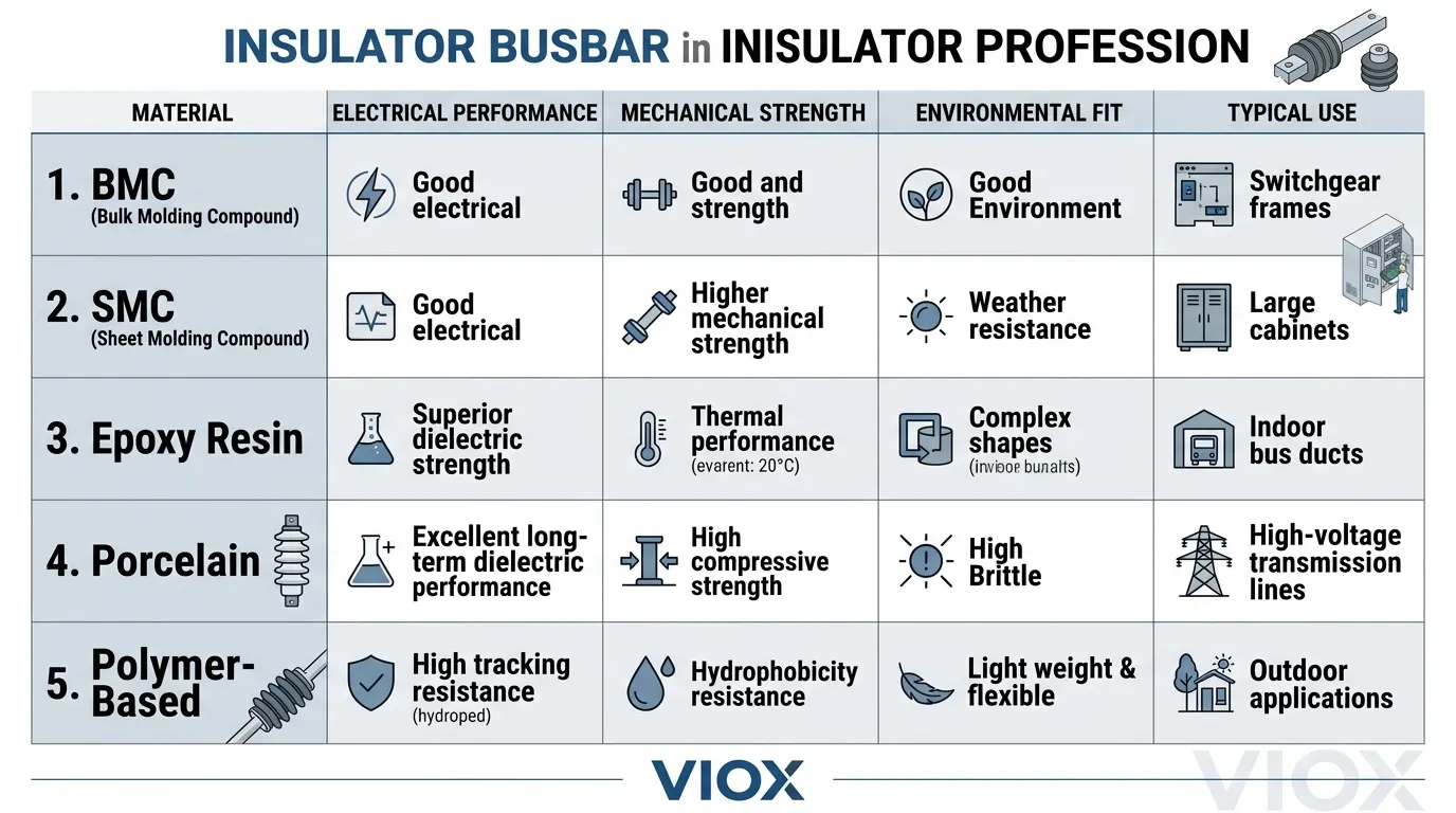
BMC or SMC-based molded insulators
Bulk Molding Compound (BMC) and Sheet Molding Compound (SMC) are thermoset polyester-based composites reinforced with glass fibers. They are the workhorse materials for low-voltage busbar insulators because they deliver a practical balance of properties at reasonable cost:
- Good dielectric strength (typically 10–15 kV/mm)
- Operating temperature capability up to 130–160 °C depending on formulation
- Solid mechanical strength and impact resistance
- Excellent moldability for complex shapes and integrated hardware features
- Good resistance to tracking and arc erosion (CTI values commonly ≥ 600 V for quality grades)
Best fit: Low-voltage distribution panels, switchgear assemblies, motor control centers, and general industrial power applications.
Epoxy-based systems
Epoxy resins — often glass-filled or mineral-filled — can deliver superior dielectric performance, tighter dimensional tolerances, and excellent moisture resistance. They are commonly used in medium-voltage insulation systems and in specialized low-voltage applications where higher performance is justified.
Best fit: Engineered assemblies, medium-voltage switchgear components, applications requiring superior moisture resistance or tighter dimensional control.
Porcelain
Glazed porcelain has been used in electrical insulation for over a century. It offers excellent resistance to surface tracking, UV degradation, and chemical attack. Its primary disadvantages are weight and brittleness.
Best fit: Outdoor installations, legacy systems, high-pollution environments where ceramic surface performance is advantageous, and applications where weight is not a constraint.
Polymer and composite materials
Modern polymer systems — including cycloaliphatic epoxies, silicone rubber composites, and advanced thermoplastics — offer options for specialized conditions. They can provide hydrophobic surfaces that resist contamination buildup, lighter weight than porcelain, and tailored mechanical properties.
Best fit: Outdoor-exposed systems, contaminated or coastal environments, installations where lighter weight reduces structural requirements, and applications needing hydrophobic surface properties.
Practical material rule
For a standard indoor low-voltage panel operating in a clean, dry environment, BMC or SMC-based molded insulators are almost always the right starting point. They offer the best combination of performance, availability, and cost-effectiveness for this application class.
If the application is outdoor, exposed to pollution or chemicals, subject to extreme temperatures, or mechanically unusual, the material decision requires more careful analysis — and the default choice may not be adequate.
5. Review the Environment Carefully
The same insulator can perform reliably for decades in one environment and fail within years — or even months — in another. Environmental assessment is not optional; it is a core part of the selection process.
Evaluate each of the following factors for the intended installation site:
- Ambient temperature. Will the insulator experience sustained temperatures above its material rating? Consider both external ambient and internal panel temperature rise.
- Humidity. Sustained relative humidity above 80% can degrade surface insulation resistance and promote tracking on susceptible materials.
- Condensation risk. Temperature cycling that causes moisture to condense on insulator surfaces is particularly damaging, as water films bridge creepage paths.
- Dust and conductive contamination. Cement dust, coal dust, metallic particles, and other conductive or hygroscopic contaminants can drastically reduce effective insulation performance.
- Salt exposure. Coastal and marine installations subject insulator surfaces to salt deposits that become conductive when humid.
- UV exposure. Prolonged ultraviolet radiation degrades many polymer materials, causing surface cracking, chalking, and loss of hydrophobicity.
- Chemical atmosphere. Oil mist, acid vapors, solvent fumes, and other chemical exposures can attack insulator materials or degrade surface properties over time.
An insulator that performs well in a clean, climate-controlled indoor panel may be entirely wrong for a paper mill, a cement plant, a coastal substation, or an outdoor solar inverter installation.
This assessment is especially critical for:
- Coastal and offshore sites
- Heavy industrial facilities (mining, smelting, chemical processing)
- Renewable energy installations (solar farms, wind turbines) with outdoor or semi-outdoor enclosures
- Food and beverage processing plants with regular washdowns
- Tropical or high-humidity climates
6. Confirm Creepage, Clearance, and Busbar Spacing
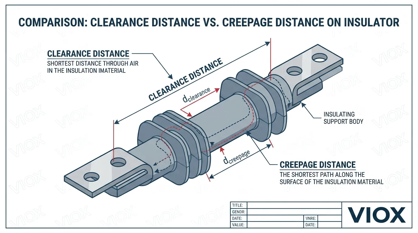
Busbar insulator selection must support the required insulation distances of the complete assembly — not just the insulator in isolation.
The insulator’s height, profile shape, and surface geometry directly affect the achievable creepage and clearance distances in the final installation. These must be reviewed together with:
- Phase-to-phase busbar spacing. The insulator height and profile must work with the specified inter-phase distance.
- Busbar-to-enclosure wall distance. Grounded enclosure walls near the busbar create clearance and creepage requirements that the insulator must help satisfy.
- Proximity to grounded metalwork. Mounting brackets, structural members, and adjacent equipment may reduce available insulation distances.
- Adjacent phase arrangement. In tightly spaced three-phase configurations, the insulator profile affects the total available creepage between phases.
- Pollution degree. Higher pollution degrees (per IEC 60664-1) demand longer creepage distances, which may require taller insulators or those with ribbed profiles.
A critical point: if the insulator body is selected in isolation — without considering the actual busbar routing, phase arrangement, and surrounding metalwork — the final panel assembly may still fail to meet the required insulation distances, even when the insulator’s own datasheet looks adequate.
To understand the difference between these two critical distance measurements, see Creepage Distance vs Clearance Distance. For a deeper explanation of creepage specifically, see What Is Creepage Distance and How to Measure It.
7. Check Mounting Dimensions and Hardware Compatibility
This is one of the most practical — and most frequently overlooked — parts of busbar insulator selection. An electrically and mechanically perfect insulator is useless if it does not physically fit the assembly.
Before finalizing any insulator choice, verify every dimension and interface:
- Mounting base footprint. Does the insulator base fit the available mounting area on the panel plate or structural frame?
- Overall height. Does the installed height provide sufficient busbar-to-ground clearance while fitting within the enclosure depth or section height?
- Thread size and specification. Do the top and bottom threads (typically M6, M8, M10, or M12 for low-voltage types) match the busbar hardware and mounting fasteners?
- Stud length. Is the stud long enough to pass through the busbar (including washers and nut engagement) without bottoming out or protruding excessively?
- Washer and nut compatibility. Are standard hardware sizes compatible, or does the insulator require special flat washers or lock washers?
- Busbar hole alignment. Do the insulator mounting centers match the busbar hole pattern?
- Tool access for tightening. Can the fasteners be reached and torqued properly once the busbar is assembled? This is frequently overlooked in tight panel layouts.
Many avoidable project delays, emergency reorders, and assembly-floor workarounds originate from choosing an electrically suitable insulator that simply does not fit the real hardware layout.
8. Match the Insulator to the Busbar Layout
The same busbar insulator can be an excellent choice in one layout and a poor choice in another. Context matters.
When evaluating the insulator against the actual busbar arrangement, review:
- Flat busbar or edgewise orientation. The load distribution on the insulator changes significantly depending on whether the busbar lies flat or stands on edge. Edgewise arrangements place more bending moment on the support.
- Single bar or multi-bar stack. A three-phase stack of 3 × (100 × 10 mm) busbars imposes far greater weight and fault force than a single bar. The insulator and its hardware must be rated accordingly.
- Support spacing along the busbar run. Longer spans between supports increase bending stress in the busbar and dynamic deflection during fault events. Tighter support spacing may be needed for heavier busbar sections or higher fault levels.
- Connection joints near the support point. Bolted joints, tap-off connections, and flex links near an insulator create localized weight and force concentrations.
- Thermal expansion path. If the busbar is rigidly fixed at every support point, thermal expansion has nowhere to go and creates cumulative lateral force. Some support points may need to allow limited sliding movement.
9. Think About Maintenance and Replacement Access
Selection is not only about first installation. It is also about the decades of operation that follow.
An insulator buried deep inside a dense panel assembly — where it cannot be inspected, retightened, or replaced without disassembling the entire busbar system — is a long-term liability, regardless of its initial technical suitability.
Ask these questions during the selection process:
- Can the insulator be visually inspected after assembly without removing other components?
- Is the support point accessible for periodic torque checks on the fasteners?
- Can the hardware be retightened if thermal cycling loosens the connection over time?
- If the insulator must be replaced, how much disassembly is required? Can one insulator be swapped without removing the entire busbar run?
In real-world projects, a slightly more accessible support arrangement often delivers more value over the equipment’s lifetime than a theoretically compact but maintenance-hostile design.
A Practical Selection Sequence
If you want a disciplined, repeatable process for choosing the right busbar insulator, follow this sequence:
- Define the system voltage and insulation duty. Identify Ui, Uimp, working voltage, pollution degree, and overvoltage category.
- Define the busbar layout and support geometry. Document busbar size, orientation, phase arrangement, support span, and enclosure constraints.
- Estimate mechanical loading and fault-related stress. Calculate static load, evaluate vibration exposure, and determine electrodynamic forces from the prospective fault current.
- Choose the insulator type that fits the mounting role. Match the physical form to the support function — standoff, post, bushing, or custom.
- Choose the material based on environment and thermal conditions. Match the material to the pollution degree, temperature range, UV exposure, and chemical atmosphere.
- Check creepage, clearance, and panel spacing. Verify that the insulator geometry delivers the required insulation distances in the actual assembly — not just on the datasheet.
- Verify hardware dimensions, threads, and service access. Confirm physical fit, fastener compatibility, and tool access.
- Review the final assembly, not just the individual insulator. Evaluate the insulator in the context of the complete busbar system to catch spacing, force, or access issues that only become visible at the assembly level.
This sequence is the most reliable way to avoid choosing a part that is nominally “rated” but poorly matched to the real installation.
Common Busbar Insulator Selection Mistakes
Choosing by voltage rating alone
Voltage is only one dimension of the insulator’s job. A part rated for 1000 V can still be wrong if it lacks sufficient creepage distance, cannot handle the mechanical load, or is made from a material unsuitable for the operating environment.
Ignoring fault-related mechanical stress
Short-circuit events generate electrodynamic forces that can reach thousands of newtons per meter on closely spaced busbars. Insulators that are adequate for static load may crack, shift, or lose clamping integrity under fault forces. This is one of the most common causes of busbar support failure in high-fault-level installations.
Using the same material for every environment
A BMC insulator that performs reliably for 20 years in a clean indoor panel may deteriorate within a few years in a coastal, humid, or chemically contaminated environment. Indoor and outdoor conditions — and different industrial atmospheres — require different material considerations.
Forgetting thread and mounting compatibility
Even a technically ideal insulator becomes a procurement problem if its thread size, stud length, or base dimensions do not match the actual busbar hardware and mounting arrangement. This mistake is especially common when switching suppliers or specifying insulators for a new panel design.
Treating the insulator as a standalone part
The correct selection depends on the complete busbar assembly — the busbar size, the phase arrangement, the enclosure geometry, the adjacent components, and the fault-level engineering. Evaluating the insulator in isolation from this context is the root cause of most selection errors.
Busbar Insulator Selection Checklist
Use this checklist as a final verification before confirming your insulator selection.
| Checklist Item | Confirmed? |
|---|---|
| Electrical duty (Ui, Uimp, working voltage) matches the system requirement | ☐ Yes / ☐ No |
| Mechanical load and support spacing reviewed, including fault forces | ☐ Yes / ☐ No |
| Correct insulator type chosen for the mounting role | ☐ Yes / ☐ No |
| Material matched to operating temperature and environmental conditions | ☐ Yes / ☐ No |
| Creepage and clearance distances verified in the actual assembly layout | ☐ Yes / ☐ No |
| Thread size, stud length, height, and base dimensions verified | ☐ Yes / ☐ No |
| Installation tool access and future maintenance access confirmed | ☐ Yes / ☐ No |
| Final assembly reviewed as a complete system, not just individual parts | ☐ Yes / ☐ No |
Conclusion
If you want to know how to choose the right busbar insulator, the answer is straightforward: choose it as part of the complete busbar support system, not as an isolated insulating component.
The correct selection is determined by the intersection of:
- Electrical insulation duty
- Mechanical support duty
- Insulator type and form factor
- Material properties
- Environmental conditions
- Assembly spacing and insulation coordination
- Mounting and hardware compatibility
- Long-term serviceability
In low-voltage and industrial assemblies, the best busbar insulator is never the one with the most impressive datasheet. It is the one that fits the real busbar layout, survives the actual operating environment, supports the required insulation margin over the full service life, and can be installed and maintained without difficulty.
For the broader background on what this component is and the roles it serves, see What Is a Busbar Insulator?.
FAQ
How do you choose the right busbar insulator?
Start by defining the application: system voltage, insulation duty, busbar layout, mechanical load, and operating environment. Then select the insulator type and material to match those requirements. Finally, verify creepage and clearance distances in the actual assembly, confirm hardware compatibility, and review maintenance access. The insulator should always be evaluated as part of the complete busbar system, not as a standalone part.
Is voltage rating enough to choose a busbar insulator?
No. Voltage rating establishes the baseline electrical requirement, but it is only one factor. Mechanical load capacity, material suitability for the operating environment, creepage and clearance distances in the installed configuration, thermal performance, and hardware compatibility must all be verified for a complete selection.
What material is commonly used for low-voltage busbar insulators?
BMC (Bulk Molding Compound) and SMC (Sheet Molding Compound) based molded insulators are the most common choice for low-voltage panel and switchgear applications. They provide a practical balance of dielectric strength, heat resistance (typically up to 130–160 °C), mechanical strength, and cost-effective manufacturability.
How important is mechanical strength in busbar insulator selection?
It is critically important. A busbar insulator must physically support the weight of the conductor, withstand tightening forces during installation, resist vibration over time, and survive the electrodynamic forces generated during short-circuit events. In practice, more insulator failures are caused by mechanical overload than by dielectric breakdown.
What is the most common mistake in selecting a busbar insulator?
The most common mistake is selecting based only on nominal voltage rating or catalog appearance without evaluating the actual busbar layout, mechanical forces, operating environment, and mounting constraints. This leads to insulators that look adequate on paper but fail to perform reliably in the real installation.
Should indoor and outdoor busbar insulators be selected the same way?
No. Outdoor installations — and indoor installations in contaminated, humid, or chemically aggressive environments — require more rigorous evaluation of material performance, surface tracking resistance, UV stability, moisture resistance, and pollution degree. The selection criteria and material choices that work well in clean indoor panels are often insufficient for these more demanding conditions.
What forces must a busbar insulator withstand during a short circuit?
During a short-circuit event, the electromagnetic interaction between current-carrying busbars generates electrodynamic forces that can reach several thousand newtons per meter, depending on the fault current magnitude and the spacing between conductors. The busbar insulators must absorb these peak forces without cracking, displacing the busbar, or losing mechanical integrity. This is why support spacing and insulator mechanical rating must be evaluated against the installation’s prospective fault level.
