When the utility power fails in a data center, hospital, or industrial facility, the automatic transfer switch (ATS) becomes the silent guardian between catastrophic downtime and seamless continuity. Within milliseconds to seconds, this critical device must detect the outage, evaluate backup generator availability, and transfer electrical loads—often carrying hundreds of amperes—without damage to sensitive equipment or interruption to life-safety systems.
Yet specifying an ATS involves more than selecting a current rating and voltage. Two fundamental classifications—PC class (Programmed Control) and CB class (Circuit Breaker)—define how the switch handles faults, what loads it can protect, and where it belongs in the power distribution hierarchy. The distinction is neither arbitrary nor merely academic: a PC-class ATS installed where fault protection is required leaves the system vulnerable; a CB-class unit specified where fast transfer speed matters most may introduce unnecessary cost and complexity.
For electrical engineers designing critical power systems, facility managers responsible for emergency backup infrastructure, and contractors installing transfer switches, understanding PC vs CB class is essential. This guide explains the technical differences between these ATS classifications, decodes the governing standards (UL 1008 and IEC 60947-6-1), and provides practical selection criteria for matching ATS class to real-world applications in data centers, hospitals, commercial buildings, and industrial facilities.
What is an Automatic Transfer Switch?
An automatic transfer switch (ATS) is a self-acting electrical switching device that monitors the availability of two independent power sources and automatically transfers electrical loads from one source to another when the primary source fails or falls outside acceptable voltage/frequency parameters. In most installations, the ATS switches between utility power (normal source) and an on-site emergency generator (emergency source), though it may also switch between two utility feeds, UPS systems, or other power configurations.
The fundamental role of an ATS is threefold: continuous monitoring of both power sources for voltage, frequency, and phase integrity; automatic detection of source failure or degradation beyond preset thresholds; and rapid, safe transfer of connected loads to the alternate source without creating hazardous conditions or damaging equipment.
Unlike manual transfer switches that require human intervention, an ATS operates autonomously based on programmed logic and sensing inputs. When utility voltage drops below 85-90% of nominal or exceeds 110%, the ATS controller initiates a transfer sequence: it signals the generator to start, waits for generator voltage and frequency to stabilize within acceptable limits (typically 10-30 seconds), opens the utility contactor or circuit breaker, waits through a brief open-transition interval to prevent backfeed or out-of-phase connection, then closes the generator contactor to restore power.
When utility power returns and stabilizes, the ATS executes a retransfer sequence—usually with an intentional time delay (often 5-30 minutes) to prevent nuisance transfers from momentary utility restoration—switching loads back to the utility and signaling the generator to stop.
This automatic operation is essential in facilities where human response time is unacceptable: hospital operating rooms, data center server loads, telecommunications equipment, industrial process control systems, fire pumps, and other life-safety or mission-critical applications. The ATS ensures power continuity within seconds, long before facility personnel could manually intervene.
Understanding ATS Standards: UL 1008 and IEC 60947-6-1
Automatic transfer switches are governed by two primary standards that define safety requirements, performance testing, and classification systems: UL 1008 in North America and IEC 60947-6-1 internationally.
UL 1008: Transfer Switch Equipment
UL 1008 is the U.S./Canadian standard published by Underwriters Laboratories for automatic, manual, and bypass-isolation transfer switches rated up to 10,000 amperes. The standard establishes rigorous testing requirements covering electrical endurance (10,000 transfer cycles under rated load), temperature rise limits, dielectric strength, and most critically, short-circuit withstand and close-on ratings (WCR).
The WCR defines the maximum fault current the ATS can safely withstand when closed onto a short circuit, and the fault current it can close onto without creating a hazardous condition. UL 1008 requires every listed ATS to carry a labeled WCR value, which may be expressed in two ways:
- Time-based rating: The ATS can withstand a specified fault current (e.g., 65 kA) for a defined duration (typically 3 cycles or ~50 milliseconds at 60 Hz), provided the upstream protective device clears the fault within that time.
- Specific-device rating: The ATS is tested with specific upstream circuit breakers or fuses; when installed with one of those listed devices, the ATS achieves a higher WCR than the time-based rating alone.
Specific-device ratings are generally higher because most circuit breakers clear faults faster than 3 cycles under actual test conditions. This allows smaller ATS frames to be used when the upstream protective device is known and listed, reducing cost and installation footprint. The 7th edition of UL 1008 (current revision) tightened requirements for adding breakers to specific-device tables, requiring comparison to actual trip times from UL short-circuit tests rather than manufacturers’ published maximum trip times.
For installation compliance, the available fault current at the ATS line terminals must not exceed the ATS’s labeled WCR, and if a time-based rating is used, the engineer must verify that the selected upstream device clears faults faster than the rated duration at that current level.
IEC 60947-6-1: Transfer Switching Equipment (TSE)
IEC 60947-6-1 is the international standard for transfer switching equipment (TSE) rated up to 1,000 V AC or 1,500 V DC. While UL 1008 focuses on safety and fault withstand through WCR coordination, IEC 60947-6-1 introduces a functional classification system based on the ATS’s short-circuit handling capability:
- PC Class (from IEC 60947-3, switches and disconnectors): TSE designed to make and withstand short-circuit currents but not to break them. PC-class devices rely on an upstream short-circuit protective device (SCPD) to interrupt fault currents.
- CB Class (from IEC 60947-2, circuit breakers): TSE designed to make, withstand, and break short-circuit currents. CB-class devices incorporate their own overcurrent protection releases and can independently interrupt faults.
- CC Class (from IEC 60947-4-1, contactors): Similar to PC class; based on interlocked contactors, can make and withstand but not break short-circuit currents.
These IEC classifications describe the internal switching mechanism and protection philosophy. In practice, many manufacturers use “PC class” and “CB class” terminology even for UL 1008-listed products in North America, as the mechanism distinction (contactor-based vs. breaker-based) aligns with the IEC definitions. However, it’s important to note that the PC/CB nomenclature itself is not a formal UL 1008 label—the critical UL requirement is the WCR rating and its coordination with upstream protective devices.
For engineers specifying ATS equipment, both standards matter: UL 1008 listing and WCR coordination ensure code compliance and safety in North America, while understanding IEC 60947-6-1 PC/CB classifications clarifies the underlying mechanism and helps predict operational characteristics like transfer speed, load compatibility, and protection coordination requirements.
PC Class (Programmed Control) ATS
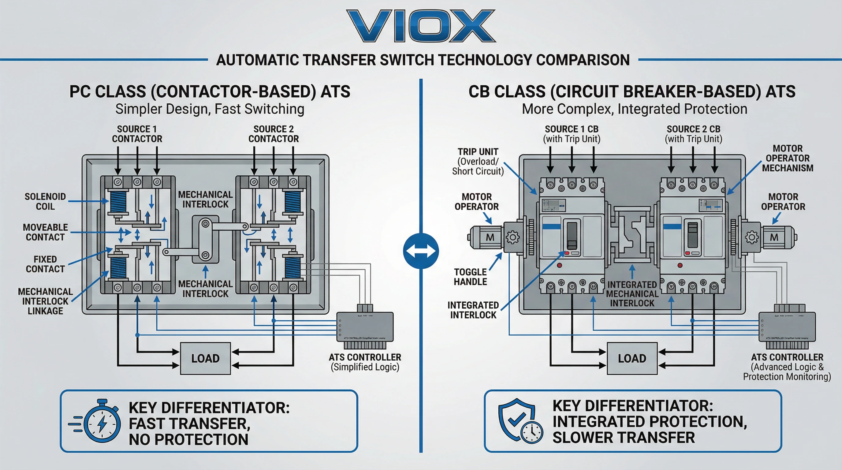
PC Class automatic transfer switches are dedicated load-transfer devices built around contactors, motorized switches, or change-over switch mechanisms. The “PC” designation originates from IEC 60947-6-1 and is sometimes expanded as “Power Control” or “Programmed Control,” though the formal IEC definition ties it to IEC 60947-3 requirements for switches and disconnectors. The defining characteristic: PC-class ATS can make and withstand short-circuit currents but are not designed to break them.
Internal Mechanism and Operation
A PC-class ATS typically uses two heavy-duty contactors—electromagnetic switching devices with silver-alloy contacts designed for high current capacity and long mechanical life. These contactors are electrically and mechanically interlocked to prevent both sources from being connected simultaneously (which would backfeed or create an out-of-phase parallel condition). A single control mechanism or motorized actuator drives the transfer, opening one contactor before closing the other in a break-before-make (open-transition) sequence.
The contactor design prioritizes fast, reliable switching. Transfer times for PC-class ATS are typically 30-150 milliseconds, depending on contactor size and control logic. This speed makes them well-suited for applications where momentary power interruption is acceptable but rapid restoration is essential, such as server power supplies with hold-up capacitors, UPS-backed loads, or non-critical distribution circuits.
No Integrated Overcurrent Protection
The critical limitation of PC-class ATS: they provide no overload or short-circuit protection. If a fault occurs downstream of the ATS, the contactor contacts can close onto the fault current and withstand it for the brief duration until an upstream protective device (circuit breaker or fuse) clears the fault, but the ATS itself cannot interrupt the fault.
This means PC-class ATS must always be protected by upstream short-circuit protective devices (SCPDs). The SCPD—typically a molded-case circuit breaker (MCCB) or fuse—must be coordinated with the ATS’s short-circuit withstand rating to ensure it clears faults before the ATS contacts are damaged. For UL 1008-listed PC-class units, this coordination is verified through the WCR rating and either time-based or specific-device tables.
Load Compatibility and Applications
Because PC-class ATS lack built-in thermal overload protection, they are versatile across a wide range of load types:
- Fast transfer for IT loads: Data center distribution panels feeding server racks, network equipment, and storage systems benefit from sub-100ms transfer times.
- Sub-distribution circuits: Branch panels in commercial buildings, hospitals, and industrial facilities where main overcurrent protection is already provided upstream.
- Mixed and resistive loads: Lighting circuits, HVAC controls, general power outlets, and other non-motor loads.
- Motor loads: PC-class ATS can handle motor starting inrush (typically 6-8× full-load current) because the upstream MCCB or fuse is sized for motor duty, not the ATS itself. This makes them suitable for pump, fan, and compressor circuits.
- Cost-sensitive projects: PC-class units are typically 20-40% less expensive than equivalent CB-class ATS, making them economical for multi-panel installations.
The reliance on upstream protection also provides a selectivity advantage: if properly coordinated, the upstream SCPD can be set to allow downstream faults to clear without tripping the main feeder, improving system reliability.
Typical Current Ratings and Physical Forms
PC-class ATS are available from 30A to 4000A, with common sizes at 100A, 260A, 400A, 600A, 800A, 1200A, 1600A, 2000A, and 3000A. They are manufactured in both open-transition (standard break-before-make) and closed-transition (make-before-break) configurations, with closed-transition models used where the brief power interruption of open-transition is unacceptable.
Selection Criteria for PC Class
Specify PC-class ATS when:
- Upstream circuit breakers or fuses provide fault protection and are coordinated with the ATS WCR
- Fast transfer speed (50-150 ms) is prioritized
- Load types include IT equipment, lighting, mixed general distribution, or motors with proper upstream protection
- Selective coordination with upstream devices is desired
- Cost optimization is important for multi-unit installations
- The application conforms to sub-distribution or branch circuit duty
Do not use PC-class where the ATS must provide its own fault interruption (e.g., main incoming feeder with no upstream SCPD), or where code or facility standards require integrated overcurrent protection in the transfer switch itself.
CB Class (Circuit Breaker) ATS
CB Class automatic transfer switches are built around circuit breakers and integrate both switching and overcurrent protection functions into a single device. The “CB” designation originates from IEC 60947-6-1 and ties to IEC 60947-2 requirements for molded-case and power circuit breakers. The defining characteristic: CB-class ATS can make, withstand, and break short-circuit currents independently, without relying on upstream protective devices.
Internal Mechanism and Operation
A CB-class ATS consists of two molded-case circuit breakers (MCCBs) or air circuit breakers (ACBs) mechanically and electrically interlocked to prevent both sources from being connected simultaneously. Each breaker includes thermal and magnetic overcurrent trip elements that can detect and interrupt overload and short-circuit conditions.
The switching mechanism is more complex than PC-class contactors. When the ATS controller commands a transfer, one breaker must open (trip or be driven open), and after a brief open-transition interval, the second breaker closes. Because circuit breakers are designed for fault interruption rather than rapid making/breaking under normal load, CB-class transfer times are typically 100-300 milliseconds—slower than PC-class units but still acceptable for most emergency power applications.
Closed-transition CB-class ATS also exist but are less common due to the complexity of momentarily paralleling two circuit breakers; static transfer switches (solid-state devices with no moving parts) are often preferred where sub-cycle transfer is required.
Integrated Overcurrent Protection
The key advantage of CB-class ATS: each circuit breaker provides its own thermal overload and magnetic short-circuit protection. If a fault occurs downstream of the ATS, or if the load exceeds the breaker’s trip setting, the breaker will open automatically to clear the fault—independent of any upstream device.
This self-sufficient protection makes CB-class ATS suitable for main incoming feeders where no upstream protective device exists between the utility service entrance and the ATS, or where facility codes require dedicated overcurrent protection at the transfer point. In hospital Essential Electrical Systems (NFPA 99) and other life-safety applications, CB-class ATS provide an additional layer of reliability because they don’t depend on coordination with upstream devices.
For UL 1008 compliance, CB-class ATS carry WCR ratings just like PC-class, but the ratings are often higher because the integrated breakers can interrupt faults quickly, allowing the ATS mechanism to withstand higher prospective fault currents. Additionally, CB-class units may carry short-time withstand ratings intended to coordinate with upstream protective relays or intentional time delays in selective coordination schemes.
Load Compatibility and Applications
CB-class ATS are designed for critical applications where integrated protection and standalone fault-clearing capability are essential:
- Main incoming service feeders: Primary ATS at the utility service entrance or generator output, feeding entire facility distribution systems in hospitals, data centers, and industrial plants.
- Critical infrastructure loads: Fire pumps, life-safety circuits, emergency lighting, and hospital operating room power where NFPA 110 and NFPA 99 mandate independent protection.
- High fault-current environments: Locations near transformers or generator outputs where prospective short-circuit currents exceed what upstream coordination alone can safely handle.
- Elevator and escalator power: Where code requires dedicated overcurrent protection for vertical transport equipment.
- Facilities requiring redundant protection: Where system design philosophy calls for multiple layers of overcurrent protection to minimize single points of failure.
Because the integrated circuit breakers provide overload protection, CB-class ATS are also suitable for motor loads, though the slower transfer time (compared to PC-class) may cause some motor-driven equipment to coast down and require restarting after transfer.
Typical Current Ratings and Physical Forms
CB-class ATS are available from 100A to 4000A, with common ratings at 225A, 400A, 600A, 800A, 1200A, 1600A, 2500A, 3200A, and 4000A. They are physically larger and heavier than equivalent PC-class units due to the circuit breaker mechanisms and arc-interruption chambers. Enclosures are typically NEMA 1 for indoor installations, with NEMA 3R or NEMA 4/4X options for outdoor or harsh environments.
Selection Criteria for CB Class
Specify CB-class ATS when:
- The ATS is installed at the main incoming service with no upstream protective device
- Code or facility standards (NFPA 110, NFPA 99, NEC Article 700/701/702) require integrated overcurrent protection at the transfer point
- Critical loads (fire pumps, hospital life-safety branches, elevators) demand independent fault-clearing capability
- High fault currents or complex selective coordination schemes require short-time withstand ratings
- System design philosophy emphasizes redundant protection layers
- The application justifies the additional cost (typically 30-50% higher than PC-class) for integrated protection
Do not use CB-class where transfer speed is critical (use PC-class or static transfer switches for <100ms transfer), or where upstream circuit breakers already provide adequate protection and selectivity (PC-class offers better economy and speed in those scenarios).
Key Technical Differences: PC vs CB Class
The choice between PC and CB class ATS hinges on several technical distinctions that directly impact system design, cost, and operational performance.
Switching Mechanism and Internal Construction
| Feature | PC Class | CB Class |
| Primary Component | Contactors or motorized switches | Molded-case or air circuit breakers |
| Mechanism Complexity | Simple electromagnetic or motor-driven contacts | Circuit breaker trip mechanism with thermal/magnetic elements |
| Physical Size | Compact; smaller footprint for equivalent rating | Larger due to breaker mechanisms and arc chambers |
| Weight | Lighter (20-40% less than CB class) | Heavier due to breaker construction |
Protection and Fault Handling
| Feature | PC Class | CB Class |
| Overcurrent Protection | None; relies entirely on upstream SCPDs | Integrated thermal overload and magnetic short-circuit protection |
| Fault Interruption | Cannot break short-circuit currents | Can independently break short-circuit currents |
| WCR Coordination | Requires coordination with upstream breakers/fuses | Higher WCR ratings due to integrated breaking capability |
| Protection Philosophy | Depends on system-level coordination | Self-sufficient; standalone protection |
Performance Characteristics
| Feature | PC Class | CB Class |
| Transfer Speed | 30-150 milliseconds (fast) | 100-300 milliseconds (moderate) |
| Electrical Endurance | 100,000+ operations typical | 10,000-50,000 operations (breaker-dependent) |
| Load Compatibility | All load types (with upstream protection) | All load types; motor loads may require restart |
| Motor Starting | Handles inrush via upstream SCPD sizing | Integrated breaker must be sized for inrush |
Application and Installation
| Feature | PC Class | CB Class |
| Typical Installation | Sub-distribution panels, branch circuits | Main incoming feeders, critical infrastructure |
| Upstream Protection | Mandatory | Optional (can be standalone) |
| Code Requirements | Suitable where upstream SCPD is present | Required where ATS must provide independent protection |
| Selectivity | Better selectivity via upstream coordination | Protection at transfer point; may limit upstream selectivity |
Cost and Economic Factors
| Feature | PC Class | CB Class |
| Equipment Cost | Lower (baseline) | 30-50% higher than equivalent PC class |
| Installation Cost | Lower; simpler wiring | Higher; larger enclosures and mounting |
| Maintenance | Minimal; contactor inspection/replacement | Breaker testing and calibration required |
| Multi-Unit Projects | Economical for multiple panels | Higher total cost for multi-panel systems |
Misapplication Consequences
Using the wrong ATS class creates predictable failure modes:
- PC-class on main incoming service without upstream SCPD: The ATS cannot clear faults. During a short circuit, the contactor will close onto the fault and remain closed, relying on utility or generator protection—which may not coordinate properly, causing equipment damage or fire risk.
- CB-class where fast transfer is critical: Slower transfer time (100-300 ms) may exceed hold-up time of sensitive IT equipment, causing server resets or data loss. Static transfer switches or PC-class ATS are better suited.
- PC-class without proper WCR coordination: If the upstream SCPD is undersized or too slow, fault currents may exceed the ATS’s withstand rating, welding contacts or causing catastrophic failure.
- CB-class in selective coordination schemes without consideration: The integrated breakers add another protection layer that must be coordinated with upstream and downstream devices; improper coordination can cause nuisance trips or loss of selectivity.
Application Guide: Data Centers, Hospitals & Industrial Facilities
Different facility types impose distinct requirements on automatic transfer switches. Understanding these application-specific needs clarifies when PC or CB class is the right choice.
Data Centers and IT Facilities
Primary Concerns: Maximum uptime (99.99%+ availability), fast transfer to minimize server disruption, selective coordination to isolate faults without cascading failures.
Typical ATS Architecture:
- Main incoming service: Often uses CB-class ATS (400A-4000A) at the utility/generator junction feeding the entire facility. Provides independent protection and high WCR ratings for the massive fault currents near the service entrance.
- Distribution to IT loads: PC-class ATS (100A-600A) at the PDU (power distribution unit) or row level. Fast transfer (50-100 ms) keeps servers online through their hold-up capacitors, and upstream MCCBs provide fault coordination and selectivity.
- Static transfer switches (STS): For Tier III/IV data centers, solid-state STS with <5ms transfer time are used between dual UPS outputs to avoid any IT load interruption. These are technically a different device class but serve similar redundancy goals.
Hospitals and Healthcare Facilities
Primary Concerns: Life-safety compliance (NFPA 99, NFPA 110), 10-second power restoration for critical branches, independent protection for essential electrical systems, maintainability without service interruption.
Typical ATS Architecture:
- Main incoming service to Essential Electrical System (EES): CB-class ATS (800A-3000A) is standard. NFPA 99 mandates that the EES be capable of independent operation, and CB-class provides the integrated protection required. This ATS feeds the life safety, critical, and equipment branches.
- Life Safety Branch (exit lighting, fire alarms, egress illumination): Dedicated CB-class ATS (100A-400A) ensures independent protection for code-mandated circuits that must remain energized during emergencies.
- Critical Branch (operating rooms, ICU, emergency department): CB-class or PC-class ATS depending on facility design. Closed-transition PC-class is common for OR power to prevent any interruption to life-support equipment; upstream coordination is carefully designed to meet NFPA selectivity requirements.
- Equipment Branch (HVAC, elevators, non-critical loads): PC-class ATS (200A-800A) is economical and provides fast transfer for less critical systems where upstream protection is acceptable.
Commercial Buildings
Primary Concerns: Code compliance for emergency/standby systems (NEC Article 700/701/702), cost-effectiveness, maintainability, adequate protection for fire pumps and egress lighting.
Typical ATS Architecture:
- Main building service: May use CB-class ATS (600A-2000A) if the ATS is at the service entrance with no upstream protection, or PC-class if located downstream of the main service disconnect.
- Fire pump: NEC Article 695 requires dedicated overcurrent protection; CB-class ATS (100A-400A) is typical to ensure the fire pump circuit has independent fault-clearing capability.
- Emergency/egress lighting: PC-class ATS (30A-100A) is economical and code-compliant where upstream breakers provide protection.
- HVAC and general standby loads: PC-class ATS for cost efficiency and fast transfer.
Industrial Facilities and Manufacturing
Primary Concerns: Process continuity, motor load handling, high fault currents near transformers, selective coordination to avoid production downtime, rugged construction for harsh environments.
Typical ATS Architecture:
- Main plant service: CB-class ATS (1200A-4000A) at the transformer secondary or generator tie point, providing high WCR ratings and independent protection for high-fault locations.
- Process control and PLC power: PC-class ATS (60A-200A) with fast transfer to keep control systems online and avoid process interruption.
- Motor loads (pumps, compressors, conveyors): PC-class ATS sized for motor starting inrush, with upstream MCCBs providing overload and short-circuit protection. Transfer may cause motor coast-down and require restart, which is acceptable in most industrial applications.
Practical Selection Guide: Choosing Between PC and CB Class
Step 1: Determine Installation Location and Protection Context
Is the ATS at the main incoming service entrance with no upstream protective device?
- Yes → CB-class required. Without upstream protection, the ATS must provide its own fault-clearing capability.
- No (ATS is downstream of main service disconnect or feeder breaker) → PC-class is feasible; proceed to Step 2.
Step 2: Identify Code and Facility Requirements
Do applicable codes (NFPA 99, NFPA 110, NEC Article 695, local AHJ requirements) mandate integrated overcurrent protection at the transfer point?
- Yes (hospitals EES, fire pumps, life-safety branches) → CB-class required.
- No → Proceed to Step 3.
Step 3: Calculate Fault Current and Verify WCR Coordination
- Determine available fault current at the ATS line terminals.
- Identify the upstream protective device (MCCB, fuse, or upstream ATS).
- For PC-class candidates: Verify the upstream device is listed in the ATS’s specific-device WCR tables, or confirm it clears faults faster than the ATS’s time-based WCR duration.
- For CB-class candidates: Verify the ATS’s labeled WCR exceeds the available fault current.
If WCR coordination cannot be achieved with PC-class → Use CB-class (higher WCR ratings typically available).
Step 4: Evaluate Transfer Speed Requirements
Does the load require transfer faster than 100 milliseconds?
- Yes (server power with limited hold-up, process control systems, IT equipment) → PC-class (30-150 ms transfer) or static transfer switches (<5 ms).
- No (general distribution, motor loads, lighting) → Both PC and CB class are acceptable.
Step 5: Assess Load Type and Operational Needs
- Sensitive IT loads, fast transfer critical → PC-class
- Motor loads with acceptable restart after transfer → PC-class (economical with upstream SCPD)
- Mixed loads requiring independent protection → CB-class
- High-inrush equipment (large motors, transformers) → PC-class (easier to coordinate via upstream SCPD sizing)
Step 6: Consider Economic and System Design Factors
- Multi-panel installations or cost-sensitive projects? → PC-class offers 20-40% cost savings per unit.
- Single critical ATS, or budget is secondary to protection robustness? → CB-class provides additional protection layer.
- Selective coordination philosophy? → PC-class allows better upstream coordination; CB-class provides independent protection at the transfer point.
Conclusion
The distinction between PC-class and CB-class automatic transfer switches is neither arbitrary nor a simple matter of preference—it defines the fundamental protection philosophy, switching mechanism, and operational characteristics of the device. PC-class ATS, built around contactors or motorized switches, provide fast, economical load transfer but rely entirely on upstream protective devices for fault clearing. CB-class ATS, constructed from circuit breakers, integrate overcurrent protection and fault interruption into the transfer switch itself, making them suitable for main service feeders and applications where independent protection is mandated or preferred.
For electrical engineers designing critical power systems, the decision hinges on installation location, code requirements, fault current coordination, transfer speed needs, and economic considerations. Main incoming services without upstream protection demand CB-class; sub-distribution panels with fast-transfer IT loads favor PC-class. Hospitals and life-safety circuits often require CB-class for code compliance; data center PDUs prioritize PC-class for speed and selectivity. Understanding the IEC 60947-6-1 classifications and UL 1008 WCR coordination framework allows engineers to make informed selections that balance protection, performance, and cost.
VIOX Electric manufactures automatic transfer switches engineered to UL 1008 and IEC 60947-6-1 standards across both PC and CB class configurations, with current ratings from 30A to 4000A for data centers, hospitals, commercial buildings, and industrial facilities. For specification guidance, WCR coordination studies, or technical consultation on your critical power transfer switching requirements, contact VIOX’s engineering team.
Specify the right ATS class for reliable critical power. Contact VIOX Electric to discuss your automatic transfer switch requirements.
