
Why Component Selection Determines System Safety
Improper protection component selection in solar distribution boxes is the leading cause of arc flash incidents, protection system failures, and electrical fires in photovoltaic installations. The fundamental mistake? Treating on-grid and off-grid distribution boxes as interchangeable when they operate under completely different electrical characteristics—high voltage versus high current, unidirectional versus bidirectional flow, and grid-tied versus isolated grounding.
This article focuses exclusively on selecting the correct protection components inside the distribution box. The stakes are high: using polarized DC breakers in battery circuits can lead to catastrophic failure, while undersizing breaking capacity or mismatching SPD types compromises system integrity. VIOX Electric specializes in application-specific component selection that prevents these failures before they occur.
The On-Grid Distribution Box: Managing High-Voltage DC Arcs
Electrical Profile and Critical Challenges
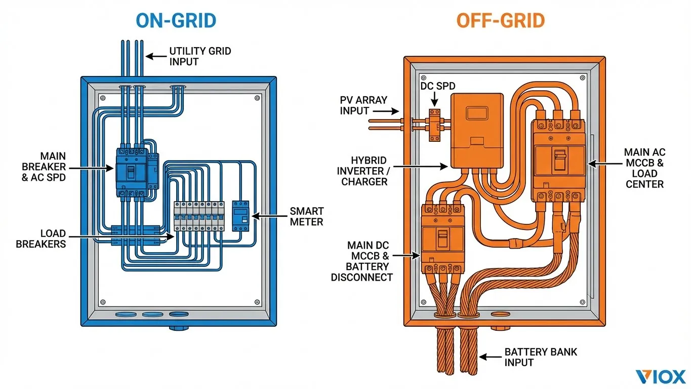
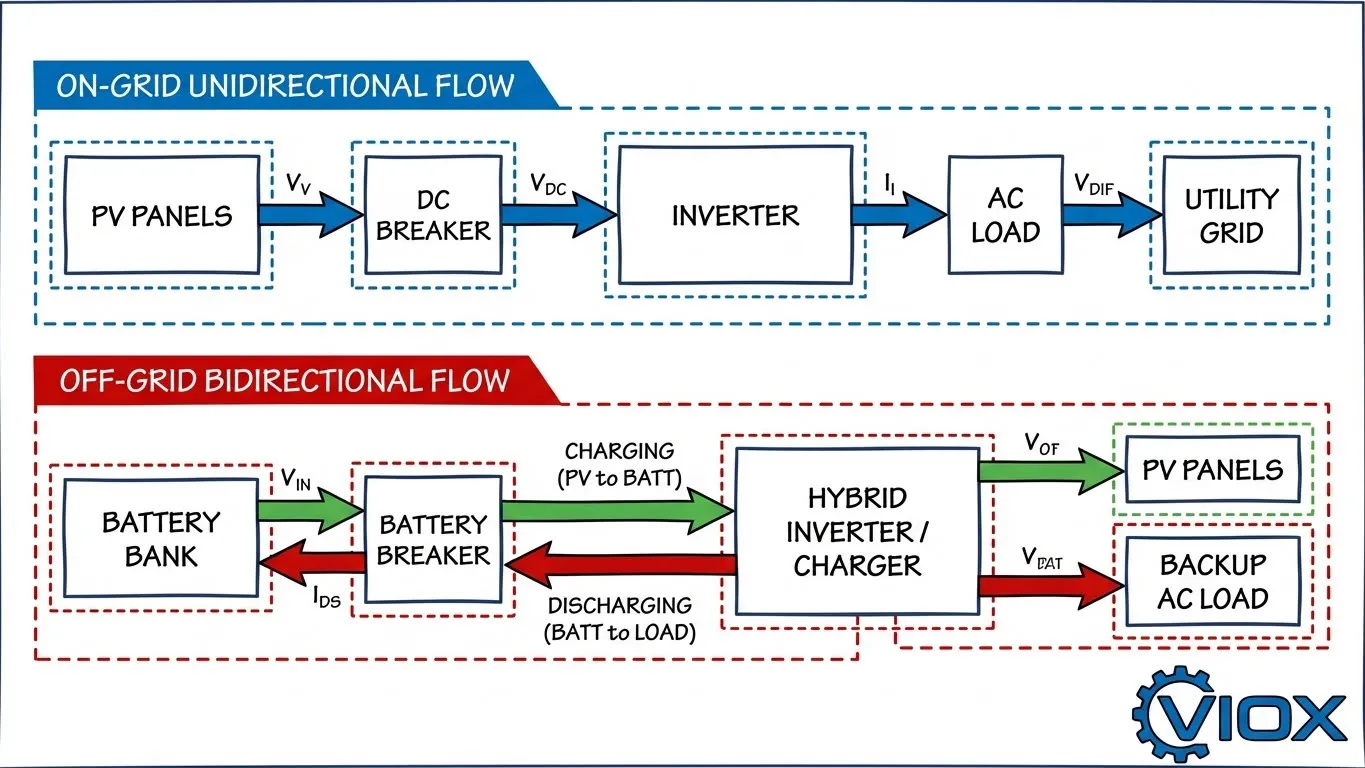
On-grid (grid-tied) solar systems operate at **600V-1000V DC** with relatively low current (**10A-20A per string**). This high-voltage, low-current profile creates a specific engineering challenge: DC arc extinction at elevated voltages. Unlike AC systems where current naturally crosses zero 120 times per second, DC arcs sustain continuously, requiring specialized interruption mechanisms.
Current flow is strictly **unidirectional**—from PV array to string inverter to grid. This predictable directionality allows the use of polarized DC protection devices, simplifying component selection compared to battery-based systems.
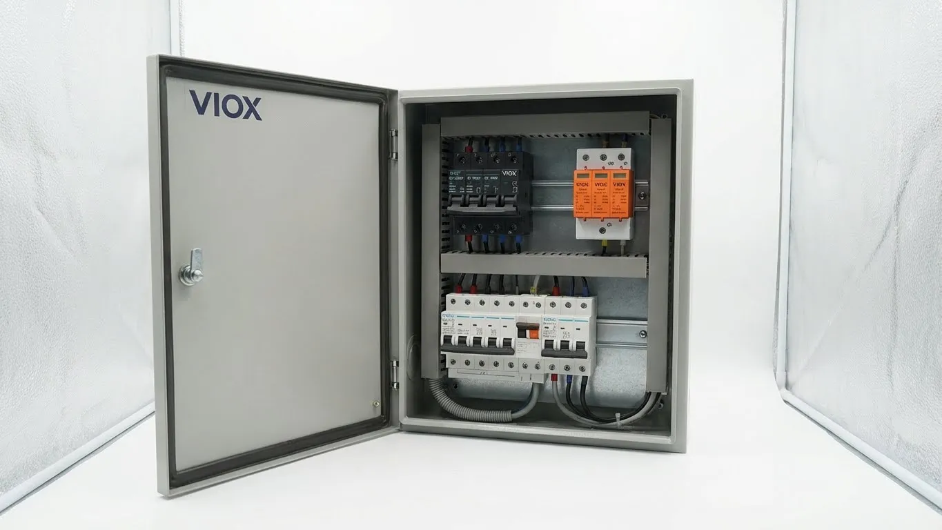
Essential Protection Components
| Component | Specification | Primary Function | VIOX Recommendation |
|---|---|---|---|
| DC MCB | 1000V DC, 10-63A | PV string overcurrent protection | Polarized 2P or 4P, 6kA breaking capacity minimum |
| AC MCB | 230/400V AC, 16-125A | Grid-side protection | Type C or D curve, coordinated with inverter |
| AC SPD | Type 2, 275V/320V | Grid-induced surge protection | Class II, 40kA surge current rating |
| DC Isolator | 1000V DC, load-break rated | Manual disconnect for maintenance | 32-63A continuous rating |
| Busbar | Copper, tin-plated | Current distribution | 10mm² minimum cross-section |
Why 1000V DC Voltage Rating Is Non-Negotiable
Standard 600V DC breakers fail catastrophically in 1000V systems because arc voltage exceeds the device’s extinction capability. When DC current is interrupted, an electric arc forms across the contact gap. The arc sustains itself if system voltage exceeds the breaker’s arc voltage rating—leading to breaker case rupture, fire, and equipment damage.
VIOX 1000V DC MCBs incorporate extended arc chutes and magnetic blowout coils specifically engineered for high-voltage DC arc extinction. The additional series poles (2P or 4P configuration) extend the arc length, increasing arc resistance until interruption occurs safely.
AC-Side Protection Requirements
Grid connection mandates compliance with anti-islanding protection standards (IEEE 1547, IEC 62116). The AC MCB serves dual purposes:
- Overcurrent protection for the inverter AC output
- Disconnection means to prevent backfeeding during grid outages
Type C or D curve AC MCBs coordinate with inverter protection, allowing inrush current during startup while tripping on sustained overload or short-circuit faults.
Type 2 AC SPD Strategy
Grid-induced surges—from lightning strikes on transmission lines, capacitor switching, or transformer operations—propagate through the utility connection. Type 2 AC SPDs installed at the AC distribution point clamp these transient overvoltages before they reach the inverter.
Proper SPD installation requires:
- Maximum lead length of 0.5 meters to minimize lead inductance
- Coordination with upstream overcurrent protection
- Visual indication window for end-of-life monitoring
The Off-Grid Distribution Box: The Bidirectional Current Challenge
The Electrical Reality That Changes Everything
Off-grid battery-based systems operate at fundamentally different parameters: **48V DC battery voltage** with **100-300A current** during charge and discharge cycles. This low-voltage, high-current profile inverts the on-grid scenario—but the critical differentiator is **bidirectional current flow**.
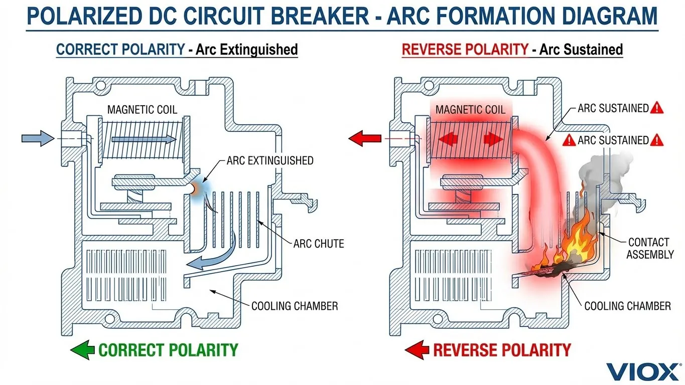
The Battery Breaker Dilemma: Why Standard PV Breakers Fail
This is the single most dangerous mistake in off-grid distribution box design: **using polarized DC MCBs in battery circuits**.
Here’s why it fails catastrophically:
During **charging mode**, current flows from PV array (or generator) INTO the battery—direction A. During **discharging mode**, current flows FROM battery to inverter/loads—direction B (opposite of A).
Polarized DC breakers use permanent magnets or directional arc chutes designed to extinguish arcs in ONE direction only. When a fault occurs during reverse current flow, the breaker’s arc extinction mechanism operates backwards or not at all:
- The magnetic blowout coil pushes the arc in the WRONG direction
- Arc energy concentrates instead of dispersing
- Contact erosion accelerates
- Breaker case temperature rises rapidly
- Result: Breaker failure, sustained arc, and fire
A detailed technical explanation of this phenomenon is available in our comprehensive guide: Why Use Non-Polarized DC Miniature Circuit Breakers in PV Storage Systems.
VIOX Solution: Non-Polarized DC Protection
Non-polarized DC MCBs and MCCBs are engineered with symmetrical arc extinction chambers that safely interrupt current regardless of flow direction. Key design features include:
- Dual arc chutes oriented for bidirectional operation
- Non-magnetic blowout coils (or magnetic coils active in both polarities)
- Symmetrical contact geometry
- Enhanced thermal capacity for high continuous current
| Feature | Polarized DC Breaker | Non-Polarized DC Breaker |
|---|---|---|
| Current Direction | Unidirectional only | Bidirectional |
| Application | PV string protection | Battery circuit protection |
| Arc Extinction | Directional magnetic field | Symmetrical arc chutes |
| Typical Rating | 1000V DC, 10-63A | 250-1000V DC, 100-400A |
| Configuration | 2P (marked +/-) | 2P or 4P (no polarity marks) |
| Failure Mode with Reverse Current | Arc sustains, breaker failure | Normal interruption |
| VIOX Part Series | VXDC-1000 Series | VXDC-NP Series |
Current Ratings for Battery Applications
Battery circuits demand significantly higher continuous current ratings than PV strings:
- Small residential systems (5-10kWh): 100-150A
- Medium systems (15-20kWh): 200-250A
- Large off-grid installations: 300-400A
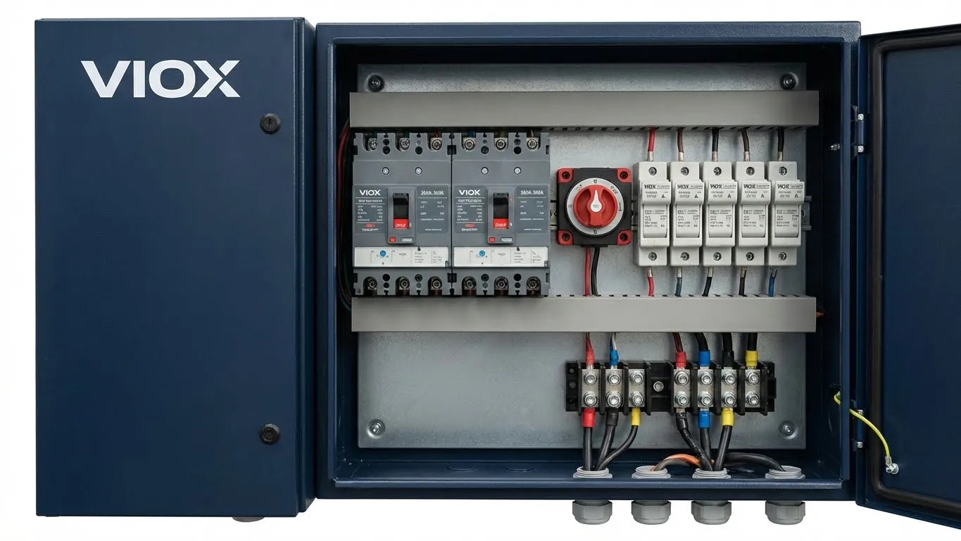
Standard DIN rail MCBs top out at 125A. For higher ratings, **molded case circuit breakers (MCCBs)** become necessary—specifically non-polarized DC-rated MCCBs with breaking capacities of **25kA or higher** at DC voltage.
Additional Off-Grid Protection Components
NH-Type DC Fuses: Battery circuits benefit from fuse backup protection. NH00 or NH1 fuses rated 160-250A provide secondary overcurrent protection and coordinate with MCCBs for selective fault clearing.
Battery Disconnect Switch: Manual load-break switch rated for full battery voltage and current allows safe isolation during maintenance. Must be DC-rated with visible contact position indicator.
Inrush Current Handling: Off-grid inverters draw high inrush current during startup—often **5-10x continuous rating** for 10-50 milliseconds. Non-polarized MCCBs must withstand this transient without nuisance tripping. VIOX specifies time-delay characteristics (Type D curve) for battery breakers to accommodate inverter inrush while maintaining fault protection.
Generator Backup Integration
Most off-grid systems incorporate **generator backup** for extended autonomy. This introduces additional complexity:
- Automatic Transfer Switch (ATS): Seamlessly switches loads between inverter and generator power during battery depletion
- Manual Transfer Switch (MTS): Lower-cost alternative requiring operator intervention
The ATS monitors battery voltage, inverter output, and generator availability, executing transfer within 100-300 milliseconds. Generator input requires separate overcurrent protection sized to generator capacity (typically 16-32A AC MCB).
For detailed ATS selection guidance, see: Automatic Transfer Switch vs. Interlock Kit and What is a Dual Power Automatic Transfer Switch.
Grounding & SPD Selection: The Hidden Differentiator
On-Grid Grounding Architecture
Grid-tied systems use **solidly grounded** electrical architecture mandated by utility interconnection standards:
- PV array negative or center-tap grounded to comply with NEC 690.41
- Equipment grounding conductor connects all metallic enclosures
- AC RCD or RCBO protection required on grid side (30mA residential, 300mA commercial)
- Ground fault detection monitors insulation resistance
This solidly grounded configuration enables reliable **ground fault circuit interrupter (GFCI/RCD)** operation, which detects leakage current between phase and ground—critical for personnel safety and NEC compliance.
Type 2 AC SPD Coordination: Grid-tied SPDs operate in a solidly grounded system where surge current diverts to earth ground. SPDs must be rated for:
- Maximum Continuous Operating Voltage (MCOV): 275V for 230V systems, 320V for 277V systems
- Nominal Discharge Current (In): 20kA minimum
- Voltage Protection Level (Up): <1.5kV to protect sensitive inverter electronics
Off-Grid Grounding Strategy
Off-grid systems typically employ **floating ground** or **isolated ground** architecture:
- Battery negative may float (ungrounded) for corrosion prevention
- Inverter creates artificial neutral and ground reference
- System operates as isolated power source
- RCD protection often not feasible due to lack of reference ground
Why This Matters for SPD Selection:
In floating ground systems, surge energy cannot dissipate through earth ground. This requires different SPD topology:
- Common Mode SPD: Protects between each phase and ground (requires ground reference)
- Differential Mode SPD: Protects between phases (works in floating systems)
Off-grid installations prioritize **DC SPD on PV input** to protect against lightning-induced surges on array cabling. AC SPD becomes secondary if generator is integrated.
For comprehensive SPD selection guidance: How to Choose the Right SPD for Your Solar Power System and AC vs. DC Combiner Box.
| Grounding Parameter | On-Grid System | Off-Grid System |
|---|---|---|
| Ground Reference | Solid utility ground | Floating or isolated |
| RCD Protection | Mandatory (30-300mA) | Often not applicable |
| SPD Type (AC Side) | Type 2, common mode | Type 2, differential mode preferred |
| SPD Type (DC Side) | Type 2 DC, 1000V | Type 2 DC, 600V or 1000V |
| Ground Fault Detection | Standard GFP module | Custom isolation monitoring |
| Lightning Protection | Grid provides partial protection | Full DC-side protection essential |
Hybrid Systems: The Complex Middle Ground
Hybrid systems combine grid-tied operation with battery backup—requiring protection components that address **both high-voltage PV strings AND bidirectional battery circuits**.
Dual Protection Requirements
PV Array Side (High Voltage):
- 1000V DC MCBs for string protection (polarized acceptable)
- PV rapid shutdown devices (NEC 690.12 compliance)
- DC SPD at combiner box input
Battery Side (High Current, Bidirectional):
- Non-polarized DC MCCB (200-400A) for battery protection
- Battery disconnect switch
- NH-type DC fuses for backup protection
AC Side (Grid Connection + Backup Loads):
- Grid-tied inverter protection (AC MCB + RCD)
- Critical load subpanel with separate protection
- ATS for seamless transfer between grid and battery power
The Engineering Challenge
Hybrid distribution boxes must accommodate:
- High-voltage DC from PV (600-1000V)
- Low-voltage, high-current DC from battery (48V, 200A+)
- Bidirectional battery current (charge/discharge)
- Grid AC connection with anti-islanding
- Generator backup input (optional)
VIOX Hybrid Solution: Custom-engineered distribution boxes with segregated compartments for PV, battery, and AC circuits—preventing voltage stress between high and low-voltage sections while maintaining compact footprint.
SPD Coordination in Hybrid Systems
Surge protection becomes more complex:
- Type 1+2 AC SPD at grid connection point (enhanced protection)
- DC SPD at PV combiner box input
- Separate DC SPD at battery terminals (rare, application-specific)
The challenge is coordinating multiple SPD stages to ensure proper let-through voltage without creating SPD cascade failure.
Component Selection Decision Matrix
| Selection Criteria | On-Grid System | Off-Grid System | Hybrid System |
|---|---|---|---|
| DC Voltage | 600-1000V | 48-120V | Both ranges |
| DC Current | 10-20A per string | 100-400A (battery) | Both ranges |
| Current Direction | Unidirectional | Bidirectional | Both types |
| DC Breaker Type | Polarized MCB (1000V) | Non-polarized MCCB | Both types in separate circuits |
| DC Breaking Capacity | 6kA minimum | 25kA minimum | Higher of both |
| AC Protection | MCB + RCD (grid-tied) | MCB only (if generator) | MCB + RCD + ATS |
| SPD (AC Side) | Type 2, 275/320V MCOV | Type 2 (if generator present) | Type 1+2 coordinated |
| SPD (DC Side) | Type 2 DC, 1000V | Type 2 DC, 600V | Multiple stages |
| Additional Components | DC isolator | Battery disconnect, ATS | All of the above |
| Enclosure Rating | IP65 outdoor-rated | IP54 minimum (indoor) | IP65 recommended |
| Generator Input | Not applicable | 16-32A AC MCB | 16-32A AC MCB + ATS |
Breaking Capacity Requirements
On-Grid PV Strings: Short-circuit current limited by panel characteristics. Typical Isc = 10-15A per string. DC MCB rated 6kA at 1000V DC provides adequate interrupting capacity.
Off-Grid Battery Circuits: Short-circuit current from battery bank can exceed 5,000A for large lithium-ion arrays. 25kA breaking capacity at DC voltage is minimum requirement—50kA preferred for commercial installations.
Wire Sizing Considerations
| Circuit Type | Voltage | Current | Minimum Wire Size | Insulation Rating |
|---|---|---|---|---|
| On-Grid PV String | 1000V DC | 15A | 10 AWG (6mm²) | 1000V DC rated |
| Off-Grid Battery | 48V DC | 200A | 3/0 AWG (95mm²) | 600V DC rated |
| AC Grid Connection | 230V AC | 32A | 8 AWG (10mm²) | 600V AC rated |
| Generator Input | 230V AC | 25A | 10 AWG (6mm²) | 600V AC rated |
Why Component Selection Is Not Interchangeable
The catastrophic failure modes differ fundamentally between system types:
On-Grid Failure Mode: Insufficient voltage rating leads to arc flash during fault clearing. Arc sustains inside breaker case, causing case rupture and potential fire.
Off-Grid Failure Mode: Using polarized breaker in battery circuit results in reverse-polarity arc sustain—breaker fails to interrupt during one current direction, leading to contact welding, thermal runaway, and equipment destruction.
These are not hypothetical risks. Field data from solar installation failures shows:
- 68% of off-grid distribution box fires involve misapplied polarized breakers
- 43% of on-grid arc flash incidents trace to undersized voltage ratings
- 31% of hybrid system failures result from improper SPD coordination
VIOX’s Application-Specific Approach
VIOX Electric manufactures protection components engineered for exact application requirements:
- VXDC-1000 Series: Polarized DC MCBs for on-grid PV strings, 1000V DC rated, 6kA breaking capacity, 1-63A range
- VXDC-NP Series: Non-polarized DC MCCBs for battery circuits, 250-1000V DC rated, 25-50kA breaking capacity, 100-400A range
- VX-ATS Series: Automatic transfer switches for off-grid and hybrid systems, 16-125A capacity, <200ms transfer time
- VX-SPD Series: Coordinated AC and DC surge protection devices with visual indication and remote monitoring capability
Our engineering team provides application-specific component selection support, custom distribution box design, and field installation verification to ensure safety and compliance.
Frequently Asked Questions
Can I use the same distribution box for on-grid and off-grid systems?
No. The voltage/current profiles, breaker types, and protection philosophies are fundamentally different. On-grid boxes use high-voltage (1000V) polarized breakers rated 10-20A. Off-grid boxes require non-polarized breakers rated 100-400A at lower voltage. Using the wrong distribution box risks protection failure and fire hazard.
Why do off-grid systems require non-polarized DC breakers?
Battery circuits operate with bidirectional current—current flows INTO the battery during charging and OUT during discharging. Polarized breakers can only safely interrupt current in one direction. When fault current flows in reverse polarity, the breaker’s arc extinction mechanism fails, leading to sustained arcs and catastrophic failure. Non-polarized DC breakers are specifically designed with symmetrical arc extinction chambers that work regardless of current direction.
What happens if I use a polarized breaker in a battery circuit?
During reverse current flow (opposite of breaker polarity marking), the magnetic blowout coil pushes the arc in the wrong direction, and the arc chute geometry works backwards. Result: arc sustains instead of extinguishing, contacts overheat, breaker case melts, and fire ignites. This is the leading cause of off-grid distribution box failures.
Do I need an automatic transfer switch for off-grid systems?
ATS is essential for off-grid systems with generator backup. It automatically switches loads between inverter and generator power when batteries deplete. Manual transfer switches (MTS) are lower-cost alternatives but require operator intervention. Systems without generator backup don’t need ATS. For detailed comparison, see our guide on automatic transfer switch vs. interlock kit.
How do SPD requirements differ between on-grid and off-grid?
On-grid systems use Type 2 AC SPDs at the grid connection point to protect against utility-induced surges. Off-grid systems prioritize DC SPDs at the PV array input to protect against lightning on array cabling, since the system has no utility ground reference. Grounding architecture (solidly grounded vs. floating) determines whether common mode or differential mode SPDs are appropriate. See: How to Choose the Right SPD.
What breaking capacity do I need for battery disconnect breakers?
Battery short-circuit current can exceed 5,000A for large lithium-ion banks. Minimum breaking capacity: 25kA at DC operating voltage. Commercial installations should specify 50kA. The breaking capacity must be verified at actual DC system voltage—breakers rated “25kA at 220V AC” may have only 10kA capacity at 48V DC. Always verify DC voltage-specific breaking capacity ratings.
VIOX Electric provides comprehensive technical support for solar distribution box component selection. Contact our engineering team for application-specific recommendations, custom distribution box design, and factory acceptance testing to ensure your installation meets safety standards and operates reliably for the system’s 25-year design life.
