

On this page
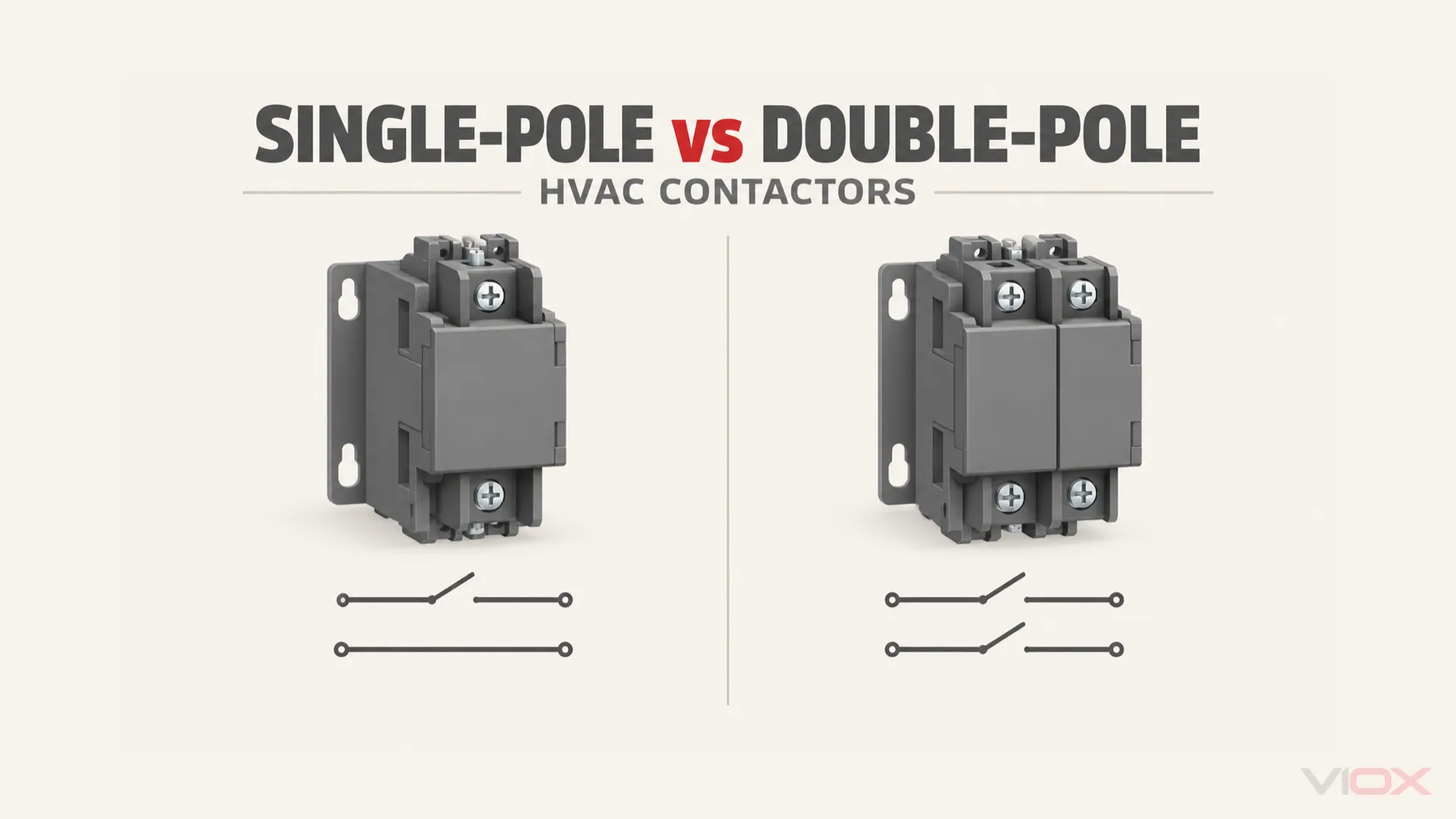
A single-pole contactor switches one power path; a double-pole contactor switches two. In heating, ventilation and air conditioning (HVAC) equipment, a device sold as a single-pole contactor may also have a fixed shunt carrying the second path. That shunt stays connected when the coil is off. A two-pole replacement changes this behavior, even if its coil voltage and amperage look suitable.
For replacement, preserve the original equipment manufacturer’s (OEM’s) approved circuit arrangement and verify the complete ratings. More switched poles are not automatically a better substitute.
| Arrangement | What operates with the coil? | What remains connected with the coil off? | Replacement implication |
|---|---|---|---|
| 1P, without a built-in shunt | One normally open main pole | Any separate, unswitched conductor in the equipment circuit | Establish where the second load conductor runs |
| 1P + fixed shunt | One normally open pole; the shunt does not switch | The fixed second path through the contactor | Check whether an off-cycle or auxiliary circuit depends on it |
| 2P, both poles normally open | Two main poles operate together | Neither corresponding load-side path remains directly connected through healthy open contacts | Confirm the original design calls for both paths to open |
Before ordering: identify the original arrangement from the equipment diagram, not just a photograph. Coil OFF is an operating state, not proof that the equipment is safe to service.
What 1P, 1P + Shunt and 2P Actually Mean
A pole is a switched main-current path. It is not a coil terminal, an auxiliary contact, or simply a terminal screw. Two connections on one end of a conductor do not create two switched poles.
Single-pole contactor: one switched path
A basic 1P normally open contactor opens one conductor when its coil releases. The other conductor needed by the load can remain connected elsewhere in the equipment circuit. Opening one series path can stop the load without removing its connection to the other supply conductor.
This distinction matters in a line-to-line circuit: the motor can be stopped while parts of its circuit remain connected to a live line.
Single-pole contactor with shunt: one switch and one permanent bridge
A 1P + shunt contactor puts two power paths in the same assembly, but only one switches. The other is a fixed conductive bridge. It can provide a convenient termination for the unswitched conductor without adding a second operating pole.
Here, shunt means that fixed power path. It does not mean a circuit breaker’s shunt-trip accessory, and it is not an auxiliary contact. Product descriptions sometimes use other shorthand, so confirm the actual contact diagram.
Four main connection positions can therefore belong to either a 1P + shunt device or a true 2P device. Counting positions cannot distinguish them.
Double-pole contactor: two switched paths
For the normally open 2P arrangement discussed here, both main contacts close when the coil operates and open when it releases. They are linked to the same operating mechanism; they are not two independently commanded switches.
The comparison does not cover mixed normally open/normally closed arrangements, latching devices or electronically controlled switching modules. Those require their own diagrams.
Coil OFF vs ON: Which Paths Stay Connected?
The following is an ideal continuity model, not a terminal-level installation drawing. It assumes healthy, non-latching contacts, no alternative supply and a simple two-conductor load. An equipment diagram may add heaters, capacitors, controls and other branches.
In this model, L1 and L2 are supply conductors; T1 and T2 identify the corresponding load-side points, with the illustrative load connected between T1 and T2. For a basic 1P device, T2 is an equipment-circuit point, not an assumed terminal on that contactor. Physical terminal placement can differ from these functional labels.
| Arrangement | Coil OFF: first path | Coil OFF: second path | Coil ON |
|---|---|---|---|
| 1P; second conductor routed separately | L1 to T1 open | L2 to T2 connected outside the contactor | First pole closes; both load paths are connected |
| 1P + fixed shunt | L1 to T1 open | L2 to T2 connected through the fixed shunt | First pole closes; shunt remains connected |
| 2P, normally open | L1 to T1 open | L2 to T2 open | Both main poles close |
The corresponding circuit relationships are:
1P, coil OFF                     1P, coil ON
L1 ---- open pole ---- T1        L1 ---- closed pole ---- T1
L2 ---- external path - T2       L2 ---- external path -- T2

1P + shunt, coil OFF             1P + shunt, coil ON
L1 ---- open pole ---- T1        L1 ---- closed pole ---- T1
L2 ---- fixed shunt -- T2        L2 ---- fixed shunt ---- T2

2P, coil OFF                     2P, coil ON
L1 ---- open pole ---- T1        L1 ---- closed pole ---- T1
L2 ---- open pole ---- T2        L2 ---- closed pole ---- T2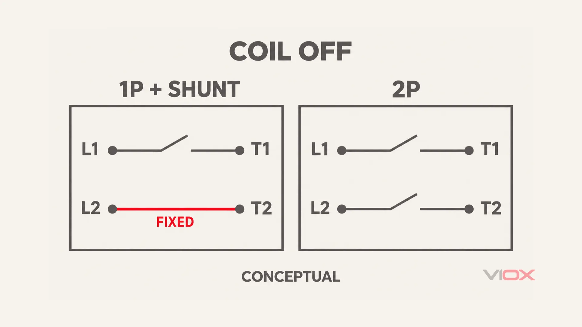
The fixed bridge remains continuous while a normally open pole has a gap. These are functional symbols, not the physical layout of a particular contactor.
In a 240 V split-phase example, L2 is not neutral
For a North American 120/240 V split-phase supply, a 240 V line-to-line load is connected between two ungrounded line conductors. Neutral is a separate conductor associated with the supply midpoint; it is not another name for the unswitched line. Michigan State University’s Electrical Tech Note 105, page 3 illustrates this supply relationship.
Some equipment also has line-to-neutral auxiliary loads. Other markets use different supply arrangements. Identify the actual circuit before deciding which conductor is switched; do not label every second conductor neutral.
For device-marking identification, use the separate guide to L1, L2, T1 and T2 on a contactor.
Can You Replace a Single-Pole Contactor with a Double-Pole Contactor?
Not automatically. A suitable 2P device may perform the required switching in an equipment-approved alternative, but moving wires position-for-position does not establish that approval. The additional contact opens a path that was previously permanent.
| Proposed change | Circuit consequence | Evidence needed before acceptance |
|---|---|---|
| 1P to matching 1P | Intended number of switched paths stays the same | Equipment-approved part or documented equivalent, correct ratings and connection map |
| 1P + shunt to matching 1P + shunt | Switched and fixed paths can be preserved | Confirm which path is the shunt and how every branch uses it |
| 1P or 1P + shunt to 2P | A previously unswitched path may now open | OEM-approved alternative or documented engineering acceptance, including off-cycle circuit behavior |
| 2P to 1P or 1P + shunt | One path that previously opened may stay connected | Do not treat as a routine equivalent; retain 2P unless the equipment design expressly authorizes the change |
| Any arrangement to a different product family | Contact duty, coil demand, interfaces or protective coordination may change | Exact model data plus equipment acceptance, not pole count alone |
Why the fixed path can matter when the compressor is off
Review the equipment diagram for any heater, control supply or auxiliary branch connected to an unswitched path. If that branch depends on continuity through the fixed bridge, adding a second switched pole can remove its off-cycle supply.
The presence of a crankcase heater does not, by itself, identify its wiring. It may have a separate feed or a different control arrangement. Likewise, a run capacitor should not be described as a universal crankcase-heating system. Only the specific equipment circuit establishes the function.
Do not improvise a jumper across a new pole or relocate heater wires to make an unsuitable replacement behave like the old device. That is a circuit modification requiring equipment-specific authority, not a general solution supplied by this comparison.
In US workplaces, OSHA 1910.303(b)(2) requires listed or labeled equipment to be used in accordance with the instructions included with its listing or labeling. A general compatibility article does not override those instructions.
The Replacement Checks That Pole Count Cannot Answer
Keep the original equipment model, wiring diagram, contactor identification and proposed replacement datasheet together. Resolve each row below before approving a substitute.
| Check | What to compare | When to stop |
|---|---|---|
| Coil supply | Rated voltage, AC/DC type, frequency where specified, operating range and control-circuit demand | Coil data are missing or differ without documented approval |
| Main circuit | Operating voltage, number of switched paths and normal contact state | A fixed path becomes switched, or a required switched path becomes fixed |
| Load duty | Motor/compressor ratings at the applicable voltage; full-load amperes (FLA), locked-rotor amperes (LRA) or other specified starting-duty rating | Only a resistive-current value is available for a motor application |
| Off-cycle branches | Every connection that must remain supplied when the coil is off | A branch’s purpose or supply path cannot be established |
| Connection interface | Terminal type, conductor acceptance, permitted number of conductors, insulation clearance and specified tightening method | Existing connections cannot be reproduced within the terminal instructions |
| Mechanical fit | Mounting pattern, enclosure clearance, orientation and access | Mounting or wire strain would require an unapproved modification |
| Protection and acceptance | Equipment instructions, approved replacement information and required protective-device coordination | The proposed part lacks the relevant documentation |
Match the coil, not just the load voltage
The voltage that operates the coil is separate from the voltage carried by the main contacts. For example, a 24 V AC control circuit and a 240 V load circuit describe two different requirements, not a contradictory nameplate.
Even matching nominal coil voltage is incomplete if supply type, frequency or coil demand differs. A replacement must work within the control system’s documented capability. The coil-voltage versus load-voltage guide explains that distinction in detail.
A larger ampere number is not a replacement approval
Compare ratings on the same basis. A contactor’s resistive rating does not establish its compressor-starting capability. A higher current label also does not establish correct coil demand, terminals, off-cycle behavior or equipment acceptance.
There is no universal 30 A-to-40 A upgrade rule. Use the rating required by the equipment for its actual load duty and voltage, together with the other compatibility checks.
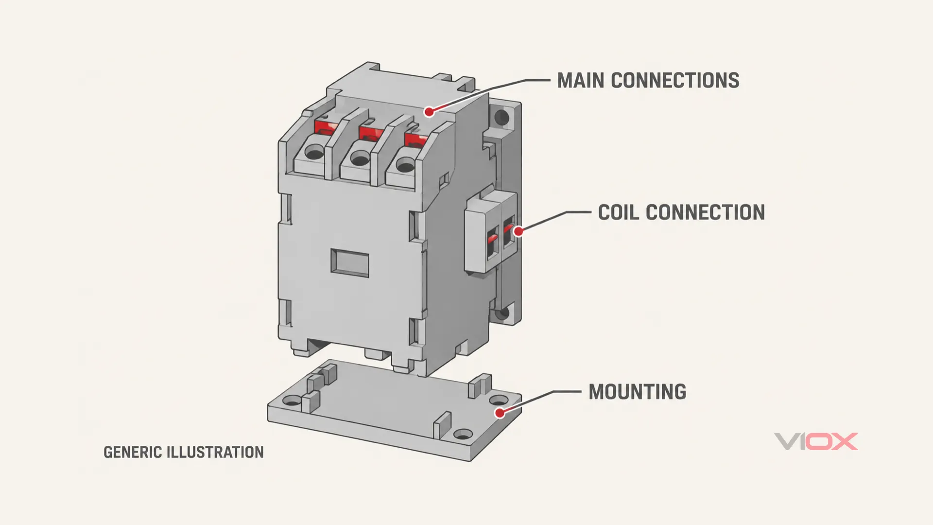
Physical fit and connection access are separate checks from electrical suitability. The illustration is generic and does not identify an approved replacement model.
Two Open Poles Do Not Establish Safe Maintenance Isolation
A 2P contactor opens two operational paths, but its line side can remain energized. Failed contacts, other feeds or stored energy can invalidate an assumption based only on coil state.
Before service, a qualified person must follow the applicable equipment and workplace procedure: disconnect all sources, apply the required lockout/tagout measures, control stored energy and verify the deenergized condition. US workplace requirements are set out in OSHA 1910.333(b).
Turning the thermostat off, removing coil voltage or seeing the contacts release is not a substitute for that process. This article compares switching functions; it is not a live-testing or replacement procedure.
HVAC Contactors Are Not the Same Selection Task as Industrial Three-Pole Contactors
This comparison concerns single-phase HVAC pole arrangements. It does not establish that a two-pole device is the appropriate controller for a three-phase motor.
A conventional three-phase contactor arrangement switches three line paths. Industrial starter selection also involves motor duty, overload protection, short-circuit coordination and accessories. Adding or removing a pole without addressing those requirements is not a valid substitution strategy.
DIN-rail modular contactors are another product family. Their pole counts, normal contact states and load ratings must be read together; see types of modular contactors for that classification. A modular housing or a matching ampere label does not make one a drop-in replacement for an HVAC definite-purpose contactor.
What to Send Before Requesting a Replacement
Provide the equipment model and serial number, original part identification, complete coil and load markings, equipment wiring diagram, and clear photos showing all main and coil connections. Include any heater or auxiliary branch connected at the contactor and the available mounting space.
The replacement decision should end in one of three outcomes: retain the documented configuration, use a documented approved alternative, or stop until missing evidence is supplied.
For a product-family review, compare the published VIOX AC contactor range. Its category page is a starting point for model data, not proof that a particular product is an approved 1P or 2P HVAC replacement. Specify the original circuit and duty before requesting a proposed model.