
Why MCCB Trip Unit Settings Matter: The Foundation of Electrical Protection
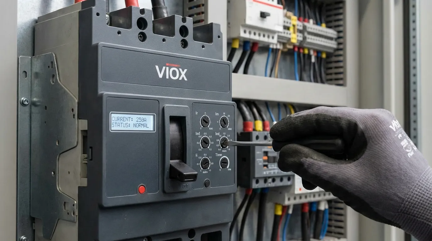
Modern electrical distribution systems demand precise, reliable protection against overloads and short circuits. At the heart of this protection lies the molded case circuit breaker (MCCB) trip unit—the “brain” that determines when and how quickly a breaker responds to fault conditions. Unlike fixed-trip miniature circuit breakers, MCCBs equipped with adjustable trip units offer engineers the flexibility to tailor protection characteristics to specific applications, optimize coordination between protective devices, and prevent unnecessary downtime from nuisance tripping.
Understanding the four fundamental trip unit parameters—Ir (long-time protection), Im (short-time protection), Isd (short-time pickup), and Ii (instantaneous protection)—is essential for anyone involved in electrical system design, panel building, or facility maintenance. Improper settings can result in inadequate protection, coordination failures, or frequent false trips that disrupt operations. This comprehensive guide explains each parameter, provides practical calculation methods, and demonstrates how to configure VIOX MCCB trip units for optimal performance and safety.
Thermal-Magnetic vs. Electronic Trip Units: Understanding the Technology
Before diving into specific parameters, it’s crucial to understand the two main types of circuit breaker trip technologies and how they differ in functionality and adjustability.
Table 1: Thermal-Magnetic vs. Electronic Trip Unit Comparison
| Feature | Thermal-Magnetic Trip Unit | Electronic Trip Unit |
|---|---|---|
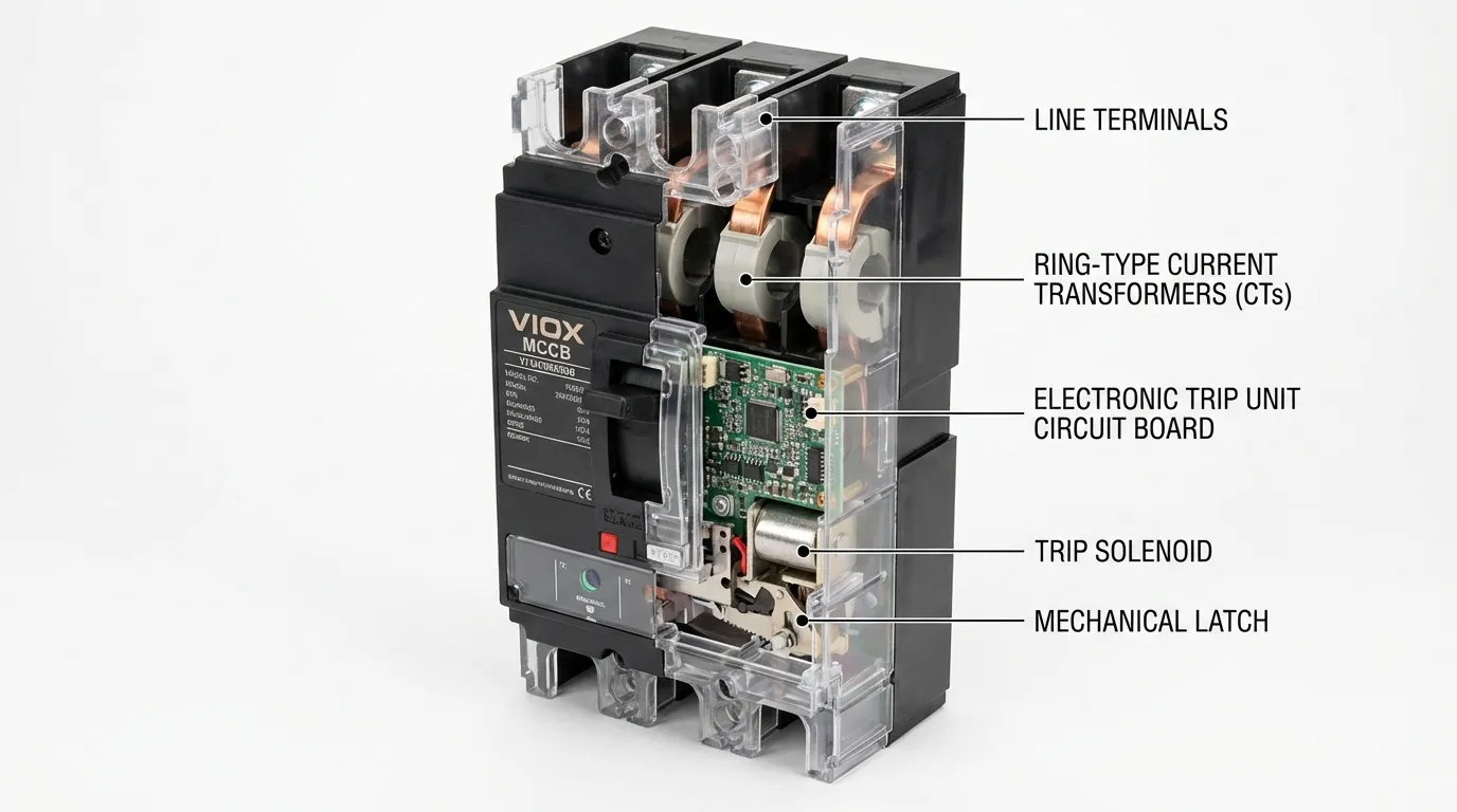
| Operating Principle | Bimetal strip (thermal) + electromagnetic coil (magnetic) | Current transformers (CTs) + microprocessor |
| Ir Adjustment | Limited or fixed (typically 0.7-1.0 × In) | Wide range (typically 0.4-1.0 × In) |
| Isd Adjustment | Not available (combined with Ii) | Fully adjustable (1.5-10 × Ir) |
| Ii Adjustment | Fixed or limited range (typically 5-10 × In) | Wide range (2-15 × Ir or higher) |
| Time Delay Adjustment | Fixed inverse curve | Adjustable tsd (0.05-0.5s typical) |
| I²t Protection | Not available | Available on advanced units |
| Accuracy | ±20% typical | ±5-10% typical |
| Temperature Sensitivity | Affected by ambient temperature | Compensated electronically |
| Ground Fault Protection | Requires separate module | Often integrated (Ig setting) |
| Display/Diagnostics | None | LCD display, event logging, communication |
| Cost | Lower | Higher |
| Typical Applications | Simple feeders, fixed loads | Motors, generators, complex coordination |
Key Insight: Electronic trip units provide far greater flexibility and precision, making them essential for applications requiring tight coordination, motor protection, or integration with building management systems. VIOX offers both technologies, with electronic units recommended for installations demanding advanced protection features.
The Four Core Protection Parameters: Ir, Im, Isd, and Ii Explained
Table 2: Trip Unit Parameter Quick Reference
| Parameter | Full Name | Protection Function | Typical Range | Time Characteristic | Primary Purpose |
|---|---|---|---|---|---|
| Ir | Long-Time Pickup Current | Thermal/Overload Protection | 0.4-1.0 × In | Inverse time (tr) | Protects conductors from sustained overloads |
| Im | Short-Time Protection | N/A (combined with Isd) | N/A | N/A | Legacy term, see Isd |
| Isd | Short-Time Pickup Current | Short-Circuit Protection with Delay | 1.5-10 × Ir | Definite time (tsd) | Allows downstream devices to clear faults first |
| Ii | Instantaneous Pickup Current | Immediate Short-Circuit Protection | 2-15 × Ir (or higher) | No delay (<0.05s) | Protects against severe faults |
| tr | Long-Time Delay | Overload trip time | Fixed inverse curve | Inverse (I²t) | Matches conductor thermal capacity |
| tsd | Short-Time Delay | Short-circuit delay | 0.05-0.5s | Definite time | Enables selectivity coordination |
Note on Terminology: The term “Im” is sometimes used interchangeably with “Isd” in older literature, but modern IEC 60947-2 and UL 489 standards primarily reference Isd for short-time pickup and Ii for instantaneous pickup. This guide uses the current standard terminology.
Ir (Long-Time Protection): Setting the Continuous Current Rating
Ir represents the continuous current rating of the trip unit—the maximum current the breaker will carry indefinitely without tripping. This is the most fundamental setting and must be carefully matched to the load and conductor ampacity.
How Ir Works
The long-time protection function uses either a bimetal strip (thermal-magnetic) or electronic sensing (electronic trip units) to monitor load current. When current exceeds the Ir setting, an inverse-time characteristic begins: the higher the overload, the faster the trip. This mimics the thermal behavior of conductors and connected equipment, providing time for temporary overloads (motor starting, transformer inrush) while protecting against sustained overloads that could damage insulation.
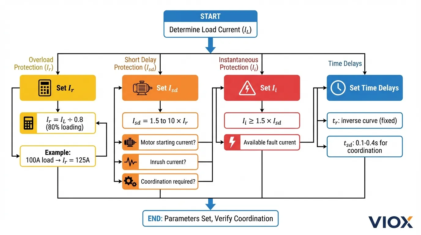
Calculating Ir
Basic Formula:
Ir = Load Current (IL) ÷ Loading Factor
Standard Practice:
- For continuous loads:
Ir = IL ÷ 0.8(80% loading per NEC/IEC) - For non-continuous loads:
Ir = IL ÷ 0.9(90% loading acceptable)
Example:
A 100A continuous load requires: Ir = 100A ÷ 0.8 = 125A
If your MCCB has In = 160A, set the Ir dial to: 125A ÷ 160A = 0.78 (round to nearest available setting, typically 0.8)
Ir Setting Considerations
- Conductor Ampacity: Ir must not exceed the ampacity of the smallest conductor in the circuit
- Ambient Temperature: Electronic trip units compensate automatically; thermal-magnetic units may require derating
- Motor Loads: Account for service factor and starting current duration
- Future Expansion: Some engineers set Ir slightly higher to accommodate load growth, but this must not compromise conductor protection
Isd (Short-Time Pickup): Coordinated Short-Circuit Protection
Isd defines the current level at which short-time protection activates. Unlike instantaneous protection, short-time protection includes an intentional delay (tsd) to allow downstream protective devices to clear faults first—the essence of selectivity coordination.
How Isd Works
When fault current exceeds the Isd threshold, the trip unit starts a timer (tsd). If the fault persists beyond the tsd delay, the breaker trips. If a downstream breaker clears the fault before tsd expires, the upstream breaker remains closed, limiting the outage to the faulted branch.
Calculating Isd
Basic Formula:
Isd = (1.5 to 10) × Ir
Selection Criteria:
- Minimum Setting: Must exceed maximum expected transient currents (motor starting, transformer inrush)
- Maximum Setting: Must be below available fault current at the breaker location
- Coordination Requirement: Must be higher than downstream breaker’s Ii setting
Example:
For Ir = 400A:
- Minimum Isd:
1.5 × 400A = 600A(avoids nuisance trips from inrush) - Typical Isd:
6 × 400A = 2,400A(common for feeder protection) - Maximum Isd: Limited by breaker’s short-circuit rating (Icu/Ics)
Isd vs. Ii: When to Use Each
- Use Isd (with tsd delay): On main and feeder breakers where selectivity with downstream devices is required
- Use Ii (no delay): On final branch circuits where immediate tripping is acceptable and no downstream coordination is needed
- Disable Isd: In some applications, Isd is set to “OFF” and only Ii is used for simplicity
Ii (Instantaneous Protection): Immediate High-Fault Protection
Ii provides instantaneous tripping (typically <50ms, often <20ms) when fault current reaches extremely high levels. This is the last line of defense against catastrophic faults that could cause arcing, fire, or equipment destruction.
How Ii Works
When current exceeds the Ii threshold, the trip unit immediately sends a trip signal to the breaker mechanism with no intentional delay. This rapid response minimizes arc energy and limits damage during severe faults like bolted short circuits.
Calculating Ii
Basic Formula:
Ii ≥ 1.5 × Isd
Selection Criteria:
- Minimum Setting: Must be at least 1.5× higher than Isd to avoid overlap
- Motor Applications: Must exceed locked-rotor current (typically 8-12 × FLA)
- Coordination: Must be lower than upstream breaker’s Isd to maintain selectivity
- Available Fault Current: Must be below the prospective short-circuit current at the installation point
Example:
For Isd = 2,400A:
- Minimum Ii:
1.5 × 2,400A = 3,600A - Typical Ii:
12 × Ir = 12 × 400A = 4,800A(common setting)
Special Considerations for Ii
- Transformer Inrush: Ii must exceed magnetizing inrush (typically 8-12× rated current for 0.1s)
- Motor Starting: For motor protection applications, Ii must exceed locked-rotor current
- Arc Flash Reduction: Lower Ii settings (where permissible) reduce arc flash incident energy
- Nuisance Tripping: Setting Ii too low causes false trips during normal switching operations
Time Delays: tr and tsd Explained
tr (Long-Time Delay)
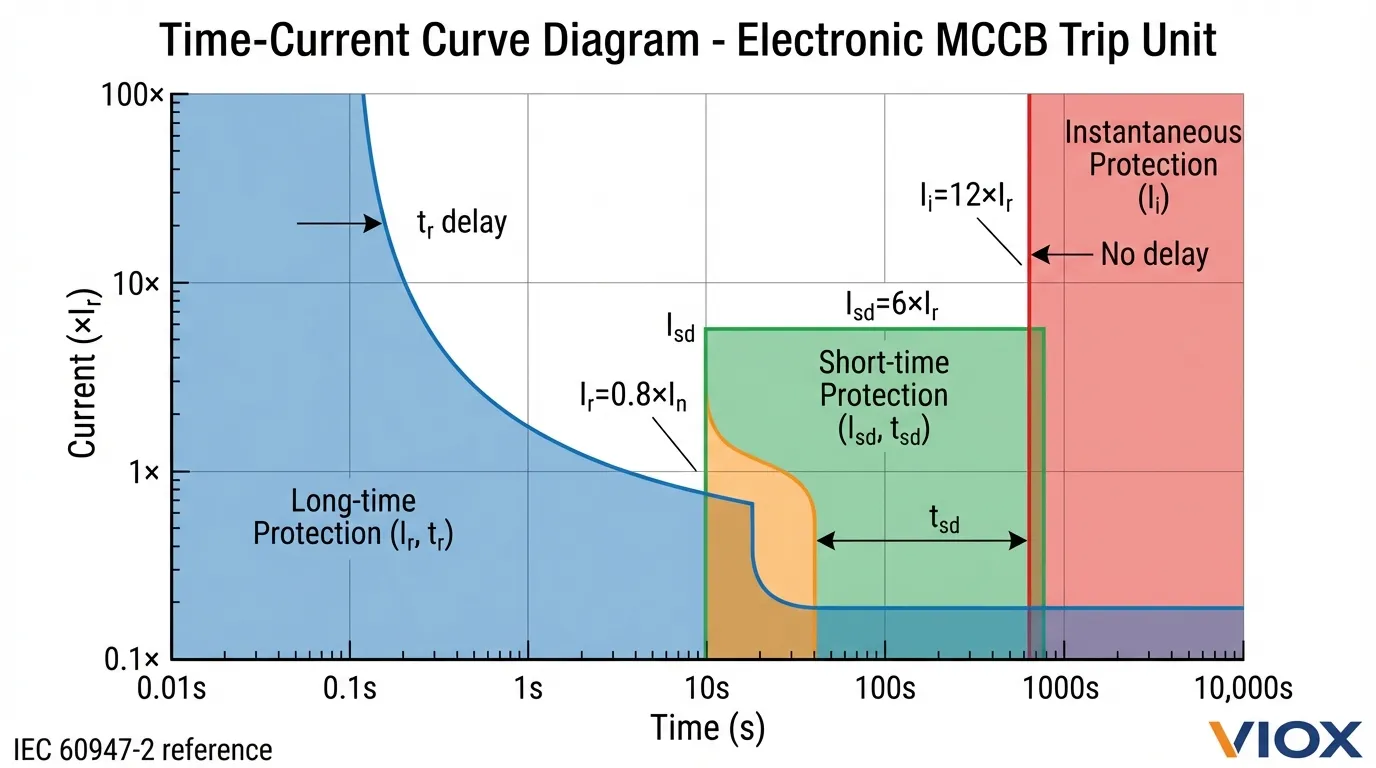
The tr parameter defines the inverse-time characteristic of the long-time protection. In most electronic trip units, tr is not directly adjustable but follows a standardized I²t curve. The curve ensures that trip time decreases as overload magnitude increases:
- At 1.05 × Ir: No trip (tolerance band)
- At 1.2 × Ir: Trip in <2 hours (electronic) or <1 hour (thermal-magnetic)
- At 6 × Ir: Trip in seconds (transition to short-time zone)
Key Point: The tr curve is factory-calibrated to match conductor thermal limits per IEC 60947-2 and UL 489. Engineers typically do not adjust tr directly but select it by choosing the appropriate trip unit model.
tsd (Short-Time Delay)
The tsd parameter is the definite-time delay for short-time protection. Common settings include:
- 0.05s: Minimum delay for basic coordination
- 0.1s: Standard setting for most applications
- 0.2s: Enhanced coordination in complex systems
- 0.4s: Maximum delay for deep coordination (requires high Icw rating)
Coordination Rule: Upstream tsd should be at least 0.1-0.2s longer than downstream breaker’s total clearing time to ensure selectivity.
I²t Protection: Thermal Memory for Enhanced Coordination
Advanced electronic trip units include I²t protection, which accounts for the cumulative heating effect of repeated overloads or faults. This “thermal memory” prevents nuisance tripping from brief, harmless current spikes while still protecting against sustained thermal stress.
When to Enable I²t:
- Motor circuits with frequent starts
- Transformer circuits with repetitive inrush
- Systems with high transient loads
- Coordination with upstream fuses
When to Disable I²t:
- Generator protection (immediate response required)
- Critical loads where any delay is unacceptable
- Simple radial systems without complex coordination needs
Practical Setting Examples by Application
Table 3: Typical Trip Unit Settings by Application
| Application | Load Current (IL) | Ir Setting | Isd Setting | Ii Setting | tsd Setting | Notes |
|---|---|---|---|---|---|---|
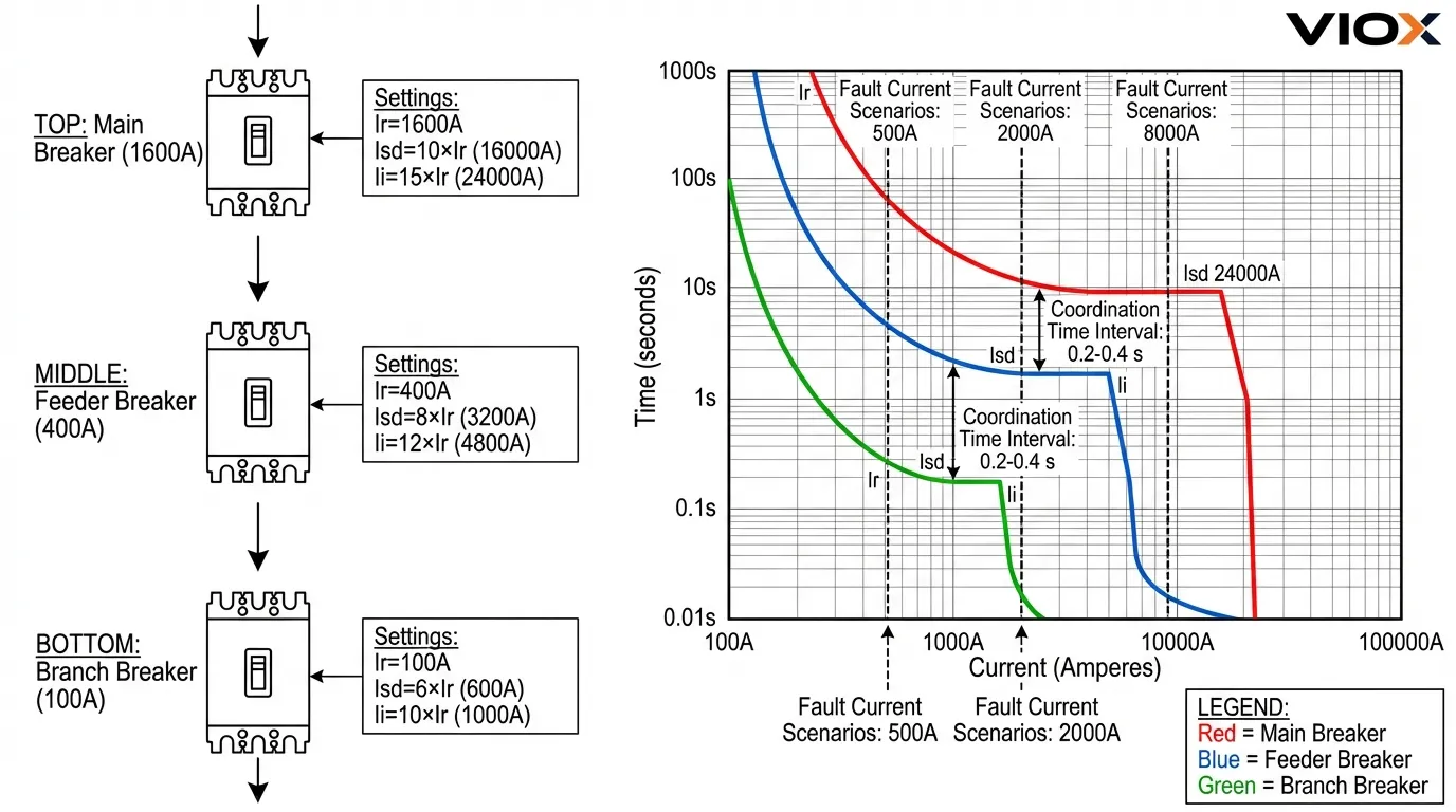
| Main Breaker (1600A) | 1280A | 1.0 × In = 1600A | 10 × Ir = 16,000A | 15 × Ir = 24,000A | 0.4s | Maximum selectivity with feeders |
| Feeder (400A) | 320A | 0.8 × In = 320A | 6 × Ir = 1,920A | 12 × Ir = 3,840A | 0.2s | Coordinates with main and branches |
| Motor Branch (100A) | 75A FLA | 0.9 × In = 90A | 8 × Ir = 720A | 12 × Ir = 1,080A | OFF (Ii only) | Accommodates 6× LRA |
| Lighting/Receptacle (63A) | 50A | 0.8 × In = 50A | OFF | 10 × Ir = 500A | N/A | Simple protection, no coordination needed |
| Transformer Primary (250A) | 200A | 0.8 × In = 200A | 10 × Ir = 2,000A | 12 × Ir = 2,400A | 0.1s | Withstands 10× inrush for 0.1s |
| Generator (800A) | 640A | 0.8 × In = 640A | 3 × Ir = 1,920A | 6 × Ir = 3,840A | 0.05s | Fast clearing to protect alternator |
| UPS Output (160A) | 128A | 0.8 × In = 128A | OFF | 8 × Ir = 1,024A | N/A | Instantaneous only, no battery damage |
Step-by-Step Setting Calculation Examples
Table 4: Setting Calculation Examples
| Step | Example 1: 400A Feeder | Example 2: 100A Motor Branch | Example 3: 1600A Main |
|---|---|---|---|
| 1. Determine Load | 320A continuous load | 75A motor (FLA), 450A LRA | 1280A total load |
| 2. Calculate Ir | 320A ÷ 0.8 = 400A Set Ir = 1.0 × 400A = 400A |
75A ÷ 0.9 = 83A Round up to 100A frame Set Ir = 0.9 × 100A = 90A |
1280A ÷ 0.8 = 1600A Set Ir = 1.0 × 1600A = 1600A |
| 3. Calculate Isd | Need coordination with 100A branches Set Isd = 6 × 400A = 2,400A |
Motor starting: 450A LRA Set Isd = 8 × 90A = 720A (Exceeds 450A LRA) |
Coordinate with 400A feeders Set Isd = 10 × 1600A = 16,000A |
| 4. Calculate Ii | Must exceed Isd by 1.5× Set Ii = 12 × 400A = 4,800A (2× Isd, good margin) |
Must exceed LRA Set Ii = 12 × 90A = 1,080A (2.4× LRA, adequate) |
Must exceed feeder Ii Set Ii = 15 × 1600A = 24,000A (5× feeder Ii) |
| 5. Set Time Delays | tsd = 0.2s (Allows 100A branches 0.1s to clear) |
tsd = OFF (Use Ii only for simplicity) |
tsd = 0.4s (Maximum selectivity) |
| 6. Verify Coordination | ✓ Isd (2,400A) > Branch Ii (1,080A) ✓ tsd (0.2s) > Branch clearing time |
✓ Ii (1,080A) < Feeder Isd (2,400A) ✓ No upstream coordination needed |
✓ Isd (16,000A) > Feeder Ii (4,800A) ✓ tsd (0.4s) > Feeder tsd + 0.2s |
Selectivity and Coordination: The Critical Relationship
Proper coordination between upstream and downstream protective devices is essential to minimize outage scope during faults. The goal: only the breaker closest to the fault should trip, leaving the rest of the system energized.
Table 5: Selectivity Coordination Rules
| Coordination Requirement | Rule | Example |
|---|---|---|
| Upstream Ir vs. Downstream Ir | Upstream Ir ≥ 2× Downstream Ir | Main 1600A, Feeder 400A (4× ratio) |
| Upstream Isd vs. Downstream Ii | Upstream Isd > Downstream Ii | Main Isd 16,000A > Feeder Ii 4,800A |
| Upstream tsd vs. Downstream Clearing Time | Upstream tsd ≥ Downstream total clearing + 0.1-0.2s | Main tsd 0.4s > Feeder (0.2s + 0.1s clearing) |
| Upstream Ii vs. Downstream Ii | Upstream Ii ≥ 2× Downstream Ii | Main Ii 24,000A > Feeder Ii 4,800A (5× ratio) |
| I²t Coordination | Upstream I²t > Downstream I²t | Main I²t ON, Feeder I²t ON or OFF |
Key Coordination Principle: Each upstream device must have higher pickup settings and longer time delays than the downstream device it protects. This creates a “cascade” of protection where the smallest breaker trips first, then the next larger, and so on.
Advanced Coordination: For complex systems, use time-current curve analysis software (many manufacturers provide free tools) to verify coordination across all fault current levels. VIOX technical support can assist with circuit protection selection and coordination studies.
Common Setting Mistakes and Solutions
Table 6: Common Setting Mistakes and Solutions
| Mistake | Consequence | Correct Approach | Prevention |
|---|---|---|---|
| Ir set too high | Conductor overheating, insulation damage | Calculate Ir based on conductor ampacity, not breaker frame size | Always verify Ir ≤ conductor ampacity |
| Ir set too low | Nuisance tripping during normal operation | Account for continuous load + safety margin (80% rule) | Measure actual load current before setting |
| Isd = Ii (no separation) | Loss of selectivity, both functions trip simultaneously | Ensure Ii ≥ 1.5 × Isd | Use manufacturer’s recommended ratios |
| tsd too short | Upstream breaker trips before downstream clears fault | Add 0.1-0.2s margin to downstream clearing time | Calculate total clearing time including arcing time |
| tsd too long | Excessive fault current duration, equipment damage | Balance coordination needs with equipment withstand ratings | Verify breaker Icw rating supports tsd duration |
| Ii set below motor LRA | Breaker trips on motor starting | Set Ii ≥ 1.2 × locked-rotor current | Obtain motor nameplate data before setting |
| Ignoring I²t | Premature tripping from harmless transients | Enable I²t for loads with frequent inrush | Understand load characteristics |
| No coordination study | Random tripping patterns, large outages | Perform time-current curve analysis | Use coordination software or consult manufacturer |
| Forgetting ambient temperature | Thermal-magnetic units trip early in hot environments | Apply derating factors or use electronic trip units | Measure actual panel interior temperature |
Pro Tip: Document all trip unit settings on panel schematics and maintain a settings database. Many electronic trip units allow settings to be uploaded/downloaded via software, making commissioning and troubleshooting much easier.
Troubleshooting Trip Unit Issues
- Symptom: Frequent nuisance tripping
- Check if Ir is set too low for actual load
- Verify Ii is not below motor starting or transformer inrush currents
- Confirm ambient temperature is within breaker rating
- Inspect for loose connections causing voltage drop and current spikes
- Symptom: Breaker fails to trip during overload
- Verify Ir setting matches load requirement
- Check if thermal-magnetic unit is temperature-compensated
- Test trip unit functionality per manufacturer procedures
- Confirm breaker has not reached end of electrical life
- Symptom: Loss of selectivity (wrong breaker trips)
- Review coordination study—upstream Isd may be too low
- Verify tsd settings provide adequate time margin
- Check if downstream breaker Ii exceeds upstream Isd
- Confirm fault current levels match design assumptions
- Symptom: Cannot set desired Ir value
- Check if rating plug (if equipped) limits adjustment range
- Verify trip unit model supports required Ir range
- Consider changing to different frame size or trip unit model
For persistent issues, VIOX technical support can provide remote diagnostics for electronic trip units with communication capabilities, or guide you through systematic testing procedures.
Integration with Modern Systems
Advanced VIOX electronic trip units offer features beyond basic LSI protection:
- Communication Protocols: Modbus RTU, Profibus, Ethernet for integration with SCADA/BMS
- Event Logging: Records trip events, load profiles, and alarm conditions
- Predictive Maintenance: Monitors contact wear, operation count, and thermal stress
- Remote Setting: Adjust parameters via software without opening panel
- Ground Fault Protection: Integrated Ig setting for personnel and equipment protection
- Arc Flash Reduction: Maintenance mode temporarily lowers Ii to reduce incident energy
These features are particularly valuable in commercial EV charging, data centers, and critical infrastructure where downtime costs are high and proactive maintenance is essential.
FAQ: MCCB Trip Unit Settings
Q: What does Ir mean on an MCCB trip unit?
A: Ir stands for “long-time pickup current” or “rated current setting.” It represents the continuous current the breaker will carry without tripping and is typically adjustable from 0.4 to 1.0 times the breaker’s nominal rating (In). For example, if you have a 400A breaker (In = 400A) and set Ir to 0.8, the effective continuous rating becomes 320A. Ir protects against sustained overloads using an inverse-time characteristic—the higher the overload, the faster the trip.
Q: How do I calculate the correct Ir setting for my load?
A: Use the formula: Ir = Load Current ÷ 0.8 (for continuous loads per NEC/IEC 80% rule). For example, a 100A continuous load requires Ir = 100A ÷ 0.8 = 125A. If your breaker has In = 160A, set the Ir dial to 125A ÷ 160A = 0.78 (round to 0.8 if that’s the nearest setting). Always verify that Ir does not exceed the ampacity of the smallest conductor in the circuit, and account for ambient temperature derating if necessary.
Q: What’s the difference between Isd and Ii?
A: Isd (short-time pickup) and Ii (instantaneous pickup) both protect against short circuits, but with different response times. Isd includes an intentional time delay (tsd, typically 0.05-0.4s) to allow downstream breakers to clear faults first, enabling selectivity. Ii provides immediate tripping (<50ms) with no delay for severe faults. Think of Isd as “coordinated protection” and Ii as “last-resort protection.” In a properly coordinated system, Ii should be set at least 1.5× higher than Isd to avoid overlap.
Q: Why do I need short-time delay (tsd) instead of instantaneous tripping?
A: Short-time delay enables selectivity—the ability to isolate only the faulted circuit while keeping the rest of the system energized. Without tsd, a fault anywhere in the system could trip the main breaker, causing a complete blackout. By adding a 0.1-0.4s delay to upstream breakers, you give downstream breakers time to clear faults first. This minimizes outage scope and improves system reliability. However, tsd requires that the breaker can withstand the fault current for the delay duration (check the Icw rating).
Q: Can I set Ii lower than Isd?
A: No, this is a common mistake that defeats the purpose of having two separate protection zones. Ii must always be higher than Isd (typically 1.5-2× higher) to maintain proper coordination. If Ii ≤ Isd, both functions would activate simultaneously during a fault, eliminating the benefit of the time-delayed short-time protection. Most modern trip units prevent this error by automatically adjusting Ii if you try to set it below Isd, but always verify your settings after adjustment.
Q: What is I²t protection and when should I use it?
A: I²t protection (also called “thermal memory”) accounts for the cumulative heating effect of current over time. It prevents nuisance tripping from brief, harmless current spikes (motor starting, transformer inrush) while still protecting against sustained thermal stress. Enable I²t for: motor circuits with frequent starts, transformer primaries, or any load with repetitive high inrush currents. Disable I²t for: generator protection (where immediate response is critical), simple radial systems, or applications where any delay is unacceptable. I²t is particularly useful for achieving coordination with upstream fuses.
Q: How do I coordinate trip settings between upstream and downstream breakers?
A: Follow these rules: (1) Upstream Ir ≥ 2× Downstream Ir to handle combined loads; (2) Upstream Isd > Downstream Ii so the downstream breaker’s instantaneous protection doesn’t overlap with upstream short-time; (3) Upstream tsd ≥ Downstream total clearing time + 0.1-0.2s margin to ensure the downstream breaker clears first; (4) Upstream Ii ≥ 2× Downstream Ii for final backup. Use time-current curve analysis software to verify coordination across all fault levels. VIOX provides free coordination assistance—contact our technical team with your system one-line diagram.
Key Takeaways
- Ir (long-time protection) sets the continuous current rating and must be calculated based on actual load current divided by 0.8 (80% loading rule), never exceeding conductor ampacity.
- Isd (short-time pickup) enables selectivity by adding an intentional delay (tsd) before tripping, allowing downstream breakers to clear faults first—essential for minimizing outage scope in coordinated systems.
- Ii (instantaneous protection) provides immediate tripping for severe faults and must be set at least 1.5× higher than Isd to maintain proper separation between protection zones.
- Electronic trip units offer far greater flexibility and precision than thermal-magnetic units, with adjustable Ir (0.4-1.0 × In), Isd (1.5-10 × Ir), and Ii (2-15 × Ir) ranges plus advanced features like I²t protection and communication.
- Coordination requires systematic planning: upstream breakers must have higher pickup settings and longer time delays than downstream devices, following the rules Upstream Isd > Downstream Ii and Upstream tsd ≥ Downstream clearing time + margin.
- I²t protection (thermal memory) prevents nuisance tripping from brief inrush currents while maintaining protection against sustained overloads—enable for motor and transformer applications, disable for generators and simple systems.
- Common mistakes include setting Ir too high (risking conductor damage), setting Ii ≤ Isd (losing selectivity), and ignoring motor starting currents (causing nuisance trips)—always verify settings against load characteristics and coordination requirements.
- Time-current curve analysis is essential for complex systems—use manufacturer-provided software or consult VIOX technical support to verify coordination across all fault current levels and ensure proper selectivity.
- Documentation and testing are critical: record all trip unit settings on panel schematics, perform commissioning tests to verify operation, and maintain a settings database for future troubleshooting and modifications.
For reliable, precisely-configured circuit protection, explore VIOX’s complete line of MCCBs with advanced electronic trip units. Our engineering team provides comprehensive support for trip unit selection, coordination studies, and commissioning assistance to ensure your electrical distribution system operates safely and efficiently. Contact us for application-specific guidance on optimizing Ir, Isd, and Ii settings for your unique requirements.
