")
Direct Answer
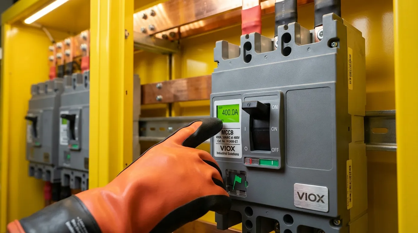
Molded Case Circuit Breakers (MCCBs) can provide short-time delay protection without a rated short-time withstand current (Icw) because they belong to IEC 60947-2 Category A, where selectivity is achieved through current-limiting technology rather than intentional time delays. Unlike Category B Air Circuit Breakers (ACBs) that “wait out” fault currents using high Icw ratings, MCCBs use electromagnetic contact repulsion and ultra-fast arc interruption to limit fault energy—protecting themselves while still coordinating with downstream devices through their inherent short-delay characteristics (typically 10-12× In) below the instantaneous trip threshold.
Key Takeaways
- ✅ Category A vs. B: MCCBs (Category A) lack declared Icw ratings but possess inherent short-time withstand capability below their contact repulsion threshold (typically >12-14× In)
- ✅ Current-Limiting Physics: Contact spring pressure is intentionally low in MCCBs to enable rapid electromagnetic repulsion at high fault currents (>25× In), preventing damage through fast interruption rather than prolonged withstand
- ✅ Short-Delay Reality: MCCB short-delay settings (e.g., 10× In, 0.4s) only function when fault current stays below the instantaneous trip threshold—exceeding this triggers immediate action via magnetic trip or energy-based mechanisms
- ✅ Selectivity Limitations: Full selectivity between MCCBs requires careful coordination tables; ACB-to-MCCB cascades achieve better results because ACBs can truly delay (Icw = Icu capability) while MCCBs handle downstream faults
- ✅ Safety Override: Advanced MCCBs with defeatable instantaneous trips (e.g., Schneider NSX) incorporate “energy trip” or “instantaneous override” functions—if fault current exceeds ~25× In, gas-actuated mechanisms force immediate tripping regardless of settings
Understanding IEC 60947-2 Selectivity Categories
Category B: ACBs with Declared Icw
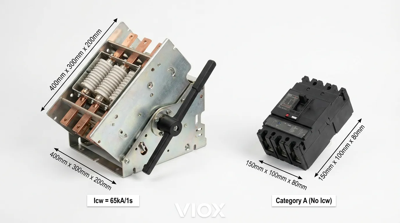
Air Circuit Breakers (ACBs) are designed for Category B applications where selectivity is achieved through intentional short-time delays. According to IEC 60947-2, these devices must declare a rated short-time withstand current (Icw)—the maximum fault current the breaker can carry in the closed position for a specified duration (0.05s, 0.1s, 0.25s, 0.5s, or 1.0s) without sustaining damage.
Key characteristics of Category B breakers:
| Parameter | Specification | Purpose |
|---|---|---|
| Icw Rating | Minimum 12× In or 5kA (≤2500A frames) Minimum 30kA (>2500A frames) |
Enables intentional delay during faults |
| Contact Design | High spring pressure | Prevents contact repulsion during delay period |
| Trip Deferrability | Instantaneous trip can be disabled | Allows pure time-based coordination |
| Typical Application | Main incomers, distribution feeders | Coordinates with downstream MCCBs |
For example, an 800A ACB with Icw = 85kA/1s can withstand 85kA fault current for up to 1 second while the short-time delay relay “waits” for downstream devices to clear the fault. This capability requires robust mechanical construction—reinforced contact arms, high contact pressure (preventing electromagnetic repulsion), and thermal mass to absorb I2t energy.
Category A: MCCBs Without Declared Icw
Molded Case Circuit Breakers (MCCBs) typically fall under Category A—devices “not specifically intended for selectivity under short-circuit conditions” per IEC 60947-2. These breakers do not declare Icw values because their design philosophy prioritizes rapid fault interruption over prolonged fault withstand.
Why MCCBs don’t declare Icw:
- Current-Limiting Design: Contact spring pressure is intentionally low to facilitate rapid electromagnetic repulsion when fault current exceeds ~10-14× In
- Instantaneous Trip Mandate: Most MCCBs cannot disable instantaneous protection—any fault exceeding the instantaneous threshold triggers immediate tripping
- Thermal Limitations: Compact molded construction cannot dissipate the thermal energy (I2t) associated with prolonged high-current withstand
However, this does not mean MCCBs lack short-time withstand capability entirely—they possess an inherent, undeclared threshold below which contacts remain closed.
The Physics of MCCB Contact Repulsion
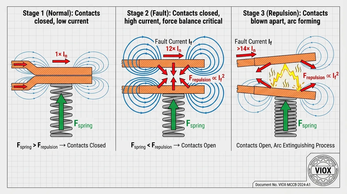
Electromagnetic Repulsion Threshold
When fault current flows through parallel contact paths in an MCCB, it generates opposing magnetic fields that create electrodynamic repulsion forces (Lorentz force). The contact spring must counteract this force to keep contacts closed.
Force balance equation:
Fspring > Frepulsion = k · I2
Where:
- Fspring = Contact spring compression force
- Frepulsion = Electromagnetic repulsion force (proportional to I2)
- k = Geometric constant (contact spacing, conductor configuration)
| MCCB Design Parameter | Category A (MCCB) | Category B (ACB) |
|---|---|---|
| Contact Spring Pressure | Low (2-5 N/mm) | High (10-20 N/mm) |
| Repulsion Threshold | 12-14× In | >50× In |
| Contact Opening Speed | 3-7 ms (ultra-fast) | 20-50 ms (controlled) |
| Design Priority | Limit fault energy (I2t) | Withstand fault duration |
Motor Starting Considerations
Research by Shanghai Electrical Research Institute on 52 motor samples revealed that direct-on-line (DOL) starting produces first-peak inrush currents of 8-12× In for most motors, with outliers reaching 13× In.
This data drives MCCB design constraints:
- Distribution MCCBs: Instantaneous trip set at 10-12× In (must not trip on capacitor inrush or transformer energization)
- Motor-Rated MCCBs: Instantaneous trip set at 13-14× In (must ride through DOL starting)
- Contact Repulsion Threshold: Must exceed instantaneous trip setting by 15-20% margin to prevent nuisance contact opening during starting transients
Example calculation for a 100A motor-rated MCCB:
Contact repulsion threshold: 1,300A × 1.2 = 1,560A (design target)
Undeclared “Icw” capability: ~1,500A (below repulsion threshold)
This 1,500A threshold represents the MCCB’s inherent short-time withstand capability—sufficient for coordination with downstream devices in the 1,000-1,500A fault range, but far below the declared Icw values of ACBs (typically 30-85kA).
How MCCB Short-Time Delay Actually Works
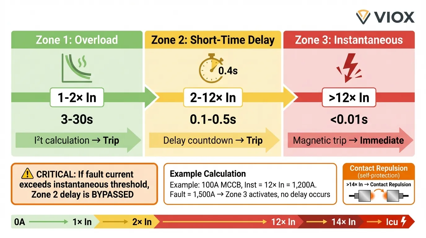
The Three Operating Zones
Modern electronic-trip MCCBs feature three protection zones, but their interaction differs fundamentally from ACBs:
| Protection Zone | Setting Range | Actual Behavior |
|---|---|---|
| Long-Time (Overload) | 0.4-1.0× In, 3-30s | Thermal protection via I2t calculation |
| Short-Time Delay | 2-12× In, 0.1-0.5s | Only active below instantaneous threshold |
| Instantaneous | 10-14× In (fixed or adjustable) | Cannot be disabled in most MCCBs |
Scenario 1: Fault Current Below Instantaneous Threshold
Conditions: Fault current = 8× In (800A for a 100A breaker)
- Current exceeds long-time zone → Short-time delay activates
- Electronic trip unit starts countdown (e.g., 0.4s)
- If fault persists, trip coil energizes after delay
- Contacts open via stored-energy mechanism (~20-30 ms opening time)
Result: True time-delayed coordination with downstream devices
Scenario 2: Fault Current Above Instantaneous Threshold
Conditions: Fault current = 15× In (1,500A for a 100A breaker)
- Current exceeds instantaneous threshold → Magnetic trip actuates immediately
- Short-time delay setting is bypassed
- Trip coil energizes within 5-10 ms
- Contacts open, but fault current may have already caused electromagnetic repulsion
Result: No intentional delay—MCCB trips as fast as possible
Scenario 3: Fault Current Far Exceeds Repulsion Threshold
Conditions: Fault current = 50× In (5,000A for a 100A breaker, approaching Icu)
- Electromagnetic repulsion force exceeds spring pressure
- Contacts blow apart within 3-7 ms (faster than trip mechanism)
- Arc voltage rises rapidly, limiting peak current (current-limiting action)
- Arc energy may trigger trip mechanism, or breaker relies on arc extinction alone
Result: Ultra-fast current limiting—no coordination, but equipment protection via I2t reduction
Special Case: MCCBs with Defeatable Instantaneous Trip
Schneider NSX “Energy Trip” Mechanism
Some high-end MCCBs (e.g., Schneider Electric NSX with Micrologic trip units) allow instantaneous protection to be disabled for improved selectivity. However, these devices incorporate a mandatory safety override called “energy trip” or “instantaneous override.”
How it works:
- User disables instantaneous trip, enables short-time delay (e.g., 10× In, 0.4s)
- Fault current reaches 30× In (3,000A for a 100A breaker)
- Contacts repel, arc forms
- Arc energy ionizes gas-generating material in arc chamber
- Pressure rise actuates pneumatic trip mechanism within 10-15 ms
- Breaker trips regardless of electronic trip unit settings
| Fault Current Level | NSX Response | Standard MCCB Response |
|---|---|---|
| 8× In | Short-time delay functions normally | Short-time delay functions |
| 15× In | Short-time delay functions (inst. disabled) | Instantaneous trip (cannot disable) |
| >25× In | Energy trip overrides delay | Contact repulsion + instant trip |
This design prevents catastrophic failure when users misconfigure protection settings—the MCCB will always self-protect at extreme fault levels, even if it compromises selectivity.
Practical Coordination Strategies
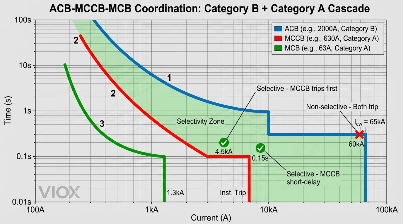
Strategy 1: ACB-to-MCCB Cascade (Recommended)
Configuration:
- Upstream: 1600A ACB, Icw = 65kA/0.5s, short-time delay = 0.4s
- Downstream: 400A MCCB, Icu = 50kA, instantaneous = 5,000A (12.5× In)
Coordination analysis:
| Fault Location | Fault Current | Upstream ACB Action | Downstream MCCB Action |
|---|---|---|---|
| Downstream feeder | 8 kA | Waits 0.4s (within Icw) | Trips instantly (>12.5× In) |
| Downstream feeder | 45 kA | Waits 0.4s (within Icw) | Trips instantly (current-limiting) |
| Main busbar | 60 kA | Trips after 0.4s | Not affected |
Result: Full selectivity up to 50kA (MCCB Icu limit)
Strategy 2: MCCB-to-MCCB Coordination (Limited)
Configuration:
- Upstream: 400A MCCB, instantaneous = 5,000A (12.5× In)
- Downstream: 100A MCCB, instantaneous = 1,300A (13× In)
Coordination analysis:
| Fault Current | Upstream MCCB | Downstream MCCB | Selectivity? |
|---|---|---|---|
| 1,500A | Short-delay (0.3s) | Instant trip | ✅ Yes |
| 4,000A | Short-delay (0.3s) | Instant trip | ✅ Yes |
| 6,000A | Instant trip | Instant trip | ❌ No (both trip) |
Selectivity limit: ~4,500A (90% of upstream instantaneous setting)
Improvement: Use manufacturer coordination tables to verify actual let-through energy—current-limiting MCCBs may still achieve selectivity at higher fault levels through I2t discrimination.
Comparison Table: ACB vs. MCCB Short-Time Characteristics
| Feature | ACB (Category B) | MCCB (Category A) |
|---|---|---|
| Icw Declaration | ✅ Yes (30-85 kA, 0.05-1.0s) | ❌ No (undeclared) |
| Inherent Withstand | Very high (>50× In) | Limited (12-14× In) |
| Contact Spring Pressure | High (prevents repulsion) | Low (enables current limiting) |
| Instantaneous Trip | Can be disabled | Usually fixed (cannot disable) |
| Short-Time Delay Range | 0.05-1.0s (adjustable) | 0.1-0.5s (only below inst. threshold) |
| Coordination Method | Time-based (true delay) | Current-based (limitation + delay) |
| Typical Application | Main incomer (1000-6300A) | Feeder protection (16-1600A) |
| Selectivity with Downstream | Full (up to Icw) | Partial (up to inst. threshold) |
| Self-Protection Mechanism | Thermal mass + mechanical strength | Contact repulsion + arc limiting |
Why This Matters for System Design
Misconception 1: “MCCB Short-Delay = ACB Short-Delay”
Reality: MCCB short-delay only functions within a narrow current window (between long-time and instantaneous thresholds). For faults exceeding instantaneous settings, MCCBs trip immediately—no delay occurs.
Design impact: When specifying MCCB protection, always verify:
- Downstream device instantaneous settings
- Maximum fault current at coordination point
- Whether fault current will exceed upstream MCCB instantaneous threshold
Misconception 2: “No Icw Rating = No Short-Time Capability”
Reality: MCCBs possess inherent short-time withstand up to their contact repulsion threshold (~12-14× In). This capability enables limited coordination with downstream devices, though not to the extent of ACBs.
Design impact: MCCB-to-MCCB coordination is possible but requires:
- Careful instantaneous setting separation (minimum 1.5:1 ratio)
- Manufacturer-provided selectivity tables
- Consideration of current-limiting effects on let-through energy
Misconception 3: “Disabling Instantaneous Trip Makes MCCB = ACB”
Reality: Even MCCBs with defeatable instantaneous trips (e.g., NSX) incorporate energy-based override mechanisms that force tripping at extreme fault levels (>25× In). They cannot “wait out” high fault currents like ACBs.
Design impact: When using MCCBs with adjustable instantaneous:
- Verify energy trip threshold with manufacturer
- Do not assume ACB-like behavior at fault currents approaching Icu
- Consider arc flash energy implications of delayed tripping
Internal Links & Related Resources
For deeper understanding of related protection concepts, explore these VIOX technical guides:
- Electrical Derating: Temperature, Altitude & Grouping Factors – Learn how environmental factors affect breaker current ratings and coordination
- ATS & Circuit Breaker Coordination Guide: Icw & Selectivity Explained – Detailed analysis of Category A vs. B coordination in automatic transfer switch applications
- Current Limiting Circuit Breaker Guide: Protection & Specs – Deep dive into electromagnetic repulsion physics and I2t limitation
- Types of Circuit Breakers: Complete Classification Guide – Comprehensive overview of ACB, MCCB, MCB differences and applications
- Commercial EV Charging Protection Guide: ACB, MCCB & Type B RCBOs – Real-world coordination example with load calculations
FAQ: MCCB Short-Time Protection
Q1: Can I use an MCCB as a main incomer instead of an ACB?
A: Possible but not recommended for systems requiring full selectivity. MCCBs lack declared Icw ratings, so they cannot reliably delay tripping for downstream coordination at high fault currents (>10× In). Use ACBs for main incomers in industrial facilities where selectivity is critical, or verify coordination limits with manufacturer tables for commercial applications.
Q2: What happens if I set MCCB short-time delay to 0.5s but fault current is 20× In?
A: The breaker will trip instantly via magnetic trip, ignoring the 0.5s delay setting. MCCB short-time delays only function when fault current stays between the short-time pickup (e.g., 2-10× In) and instantaneous threshold (e.g., 12× In). Above instantaneous, the magnetic element overrides electronic settings.
Q3: Do all MCCBs use current-limiting technology?
A: No. Thermal-magnetic MCCBs (fixed trip, no adjustability) typically use slower bimetallic overload elements and may not achieve true current limitation. Electronic-trip MCCBs with fast-acting contacts and optimized arc chutes are more likely to be current-limiting (verify with manufacturer’s let-through curves showing Ip and I2t values below prospective fault levels).
Q4: How do I verify selectivity between two MCCBs?
A: Use manufacturer coordination tables (not just time-current curves). Tables account for:
- Let-through energy (I2t) of downstream breaker
- Non-tripping energy threshold of upstream breaker
- Current-limiting effects at various fault levels
Example: Schneider Electric provides detailed selectivity tables in their coordination guides showing maximum selectivity limits (e.g., “Selective up to 15kA” between specific MCCB models).
Q5: Why do motor-rated MCCBs have higher instantaneous settings (13-14× In)?
A: To prevent nuisance tripping during direct-on-line (DOL) motor starting. Research shows motor inrush can reach 12-13× In for the first peak. Motor-rated MCCBs also have higher contact repulsion thresholds (>14× In) to ensure contacts don’t blow open during starting transients, which would cause unnecessary wear and potential welding upon reclosure.
Conclusion
The apparent paradox of MCCBs offering short-time delay protection without rated Icw values stems from a fundamental difference in protection philosophy: ACBs withstand faults through mechanical strength and thermal mass, while MCCBs limit faults through electromagnetic physics and rapid arc interruption.
Understanding this distinction is critical for electrical engineers designing coordination schemes. MCCBs can achieve selective coordination with downstream devices within their inherent short-time withstand capability (typically 12-14× In), but they cannot replicate ACB behavior at high fault currents approaching their breaking capacity. For applications requiring full selectivity across the entire fault current range, ACB main incomers coordinating with MCCB feeders remain the gold standard—leveraging Category B time-delay capabilities upstream while exploiting Category A current-limiting benefits downstream.
Key design principle: Match the breaker category to the application—use ACBs where you need to “wait out” faults, use MCCBs where you need to “kill faults fast.”
About VIOX Electric: VIOX Electric is a leading B2B manufacturer of electrical equipment, specializing in molded case circuit breakers (MCCBs), air circuit breakers (ACBs), and comprehensive protection solutions for industrial and commercial applications. Our engineering team provides technical support for complex coordination studies and system design optimization. Contact us for application-specific guidance.
