
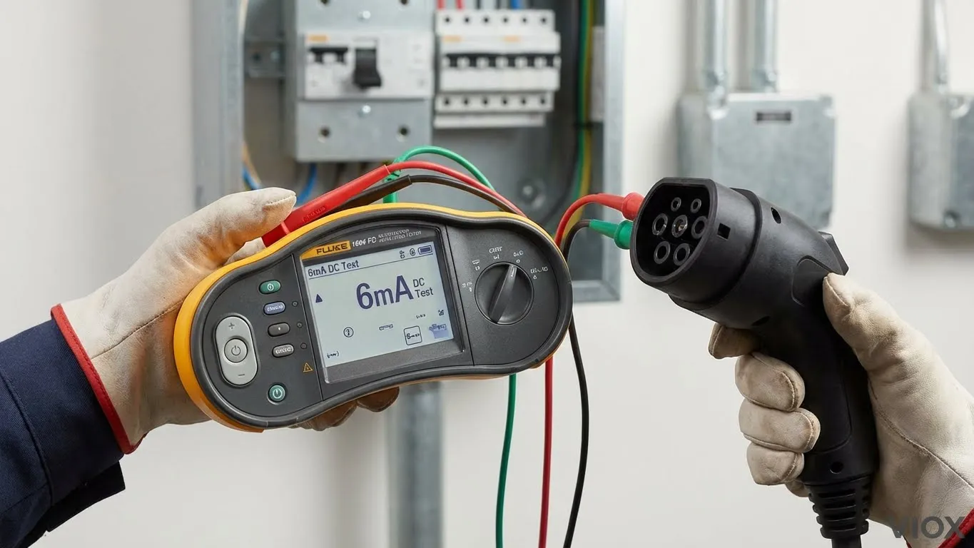
 Electrician using Fluke 1664 FC to test EV charger 6mA DC leakage protection.
If you’ve installed a commercial EV charging station, simply powering it up and checking if it charges a car isn’t enough. The invisible risk in modern EV infrastructure is DC leakage current—a phenomenon that can silently “blind” your upstream Type A RCDs, rendering the entire building’s earth leakage protection useless.
Verifying the 6mA DC trip level is the critical final step in commissioning any Mode 3 EVSE (Electric Vehicle Supply Equipment). This guide focuses purely on the practical verification of IEC 62955 compliance.
This article serves as the final installment in our EV Protection Trilogy:
- Architecture: Commercial vs. Residential EV Charging Protection (Designing the system)
- Selection: Type B vs. Type F vs. Type EV RCD Selection (Choosing the components)
- Verification: How to Test 6mA DC Protection (This guide)
Part 1: The Equipment (Why Your Standard Tester Won’t Work)
A common mistake we see in the field is contractors attempting to verify EV chargers using standard socket testers or older multifunction testers designed only for AC protection. This is dangerous and ineffective.
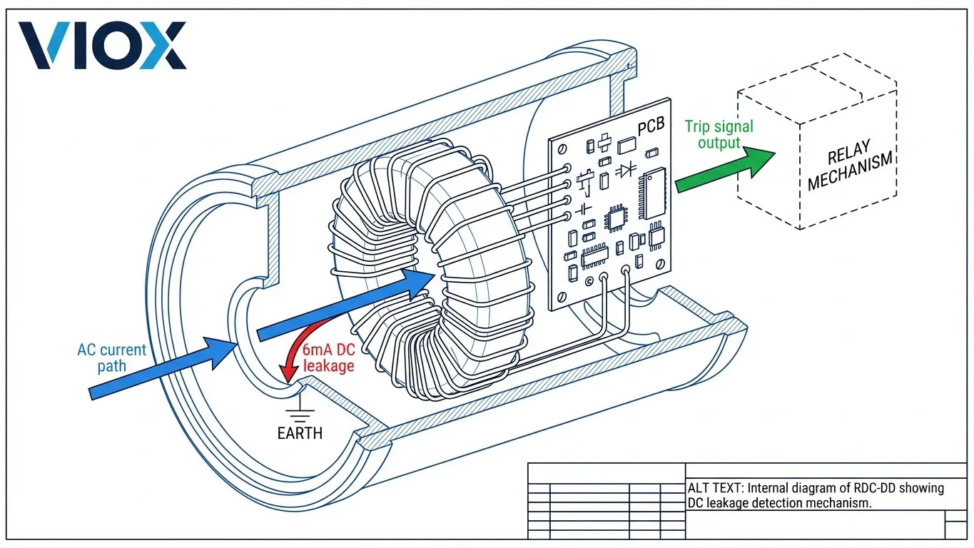
Standard RCD testers inject an AC fault current. They cannot generate the smooth DC residual current required to test an RDC-DD (Residual Direct Current Detecting Device). To verify compliance with IEC 62955, you need a tester capable of generating a precise DC ramp current starting from 2mA.
The Required Toolset
To perform this test legitimately, you must use a multifunction installation tester that specifically supports Type B / Type EV RCD testing.
Table 1: EV Charger Test Equipment Comparison
| Equipment | DC Test Capability | IEC 62955 Mode | Typical Application | Key Feature |
|---|---|---|---|---|
| Standard Socket Tester | ❌ None | ❌ No | Homeowner check | Good for wiring polarity only |
| Basic RCD Tester | ❌ AC Only (Type AC/A) | ❌ No | General domestic | Cannot detect DC leakage |
| Fluke 1664 FC + FEV300 | ✅ 6mA DC Ramp | ✅ Yes | Pro Commissioning | Auto-test sequence & safety pre-test |
| Metrel Eurotest XC/XE | ✅ 6mA DC Ramp | ✅ Yes | Pro Commissioning | Detailed EVSE specific menus |
| Megger MFT1741+ | ✅ 6mA DC Ramp | ✅ Yes | Pro Commissioning | “Confidence meter” technology |
Note: An RDC-DD is designed to detect DC leakage >6mA and disconnect the supply to prevent the upstream Type A RCD from magnetizing (saturation). If you don’t test this, you are relying on faith, not physics.
Part 2: The Procedure (Step-by-Step Verification)
Testing for DC leakage is different from standard AC RCD testing. We use a Ramp Test rather than a simple trip time test. We want to know exactly when the device trips, not just if it trips.
Step 1: Disconnect the Vehicle
Critical Safety Warning: Never perform electrical safety testing while the car is connected.
The Onboard Charger (OBC) inside the EV contains capacitors and EMI filters that can introduce capacitance to the circuit. This can absorb the test current or create noise, leading to inaccurate readings or potential damage to the vehicle’s sensitive electronics.
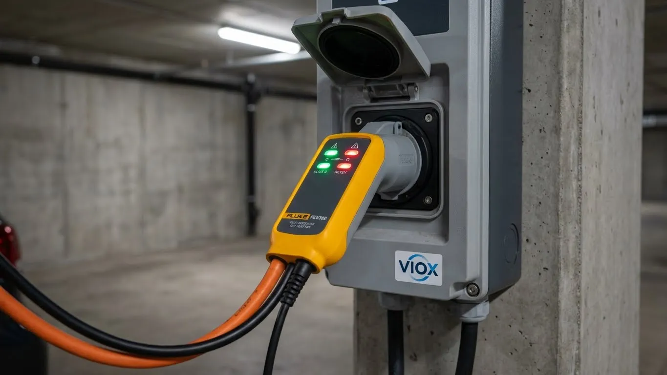
- Action: Unplug the EV. The charging station should be in “State A” (Standby) or “State B” (Vehicle Detected) via the adapter simulation.
Step 2: Connect the Test Adapter
Since you cannot safely stick probes into a live Type 2 socket, use an EV test adapter (like the Fluke FEV300).
- Plug the adapter into the charging socket.
- Set the adapter to State C (Charging) to close the EVSE contactor.
- Verify voltage presence and correct phase rotation on your tester.
- Important: Verify the Protective Earth (PE) continuity before proceeding. If the earth loop impedance is too high, the RCD test will fail regardless of the device’s quality.
Step 3: Select the DC Ramp Test
On your multifunction tester:
- Select RCD Test.
- Choose RCD Type: Type B or Type EV (varies by brand).
- Select Mode: Ramp (often symbolized by a staircase icon).
- Set Nominal Current: 6 mA.
Why Ramp? A simple “Pass/Fail” test injects 6mA immediately. If it trips, great—but was it sensitive at 2mA (too sensitive/nuisance tripping) or exactly at 6mA? The Ramp test slowly increases DC current to find the precise break point.
Table 2: Test Parameters & Acceptance Criteria
| Test Parameter | IEC 62955 Requirement | Typical VIOX Device Result | Pass/Fail Criteria |
|---|---|---|---|
| Test Current | Smooth DC (Rising) | N/A | Must be DC, not pulsating AC |
| Nominal Trip Level | 6 mA DC | 4.5 mA – 5.8 mA | Must be ≤ 6.0 mA |
| Minimum Trip Level | > 3 mA (Non-operating) | 3.5 mA – 4.0 mA | Must be > 3.0 mA (to avoid nuisance trips) |
| Trip Time | ≤ 10 seconds | < 2 seconds | ≤ 10 seconds |
| Ambient Temp | -25°C to 40°C | Room Temp | Check manufacturer derating |
Step 4: Perform the Ramp Test
Press the TEST button.
- The tester will verify the AC waveform is clean.
- It begins injecting DC current, starting around 2mA.
- The current rises in small steps (e.g., 0.5mA increments).
- SNAP! The EVSE contactor should open.
- Read the Result: The screen will display the exact current at the moment of the trip.
- Example Result: 5.4 mA (PASS)
- Example Result: >6.0 mA (FAIL – Unsafe)
- Example Result: 2.1 mA (FAIL – Too Sensitive)
Step 5: Document Results
For liability and warranty purposes, document the specific trip value.
- Take a photo of the tester screen.
- Use software like Fluke Connect to save the data to the cloud.
- Note the ambient temperature, as extreme heat can affect magnetic permeability in cheaper cores (see our Electrical Derating Master Guide).

Part 3: Troubleshooting “False Negatives”
You bought a high-quality VIOX RDC-DD, but the tester says “No Trip.” Before you blame the device, check these common installation errors.
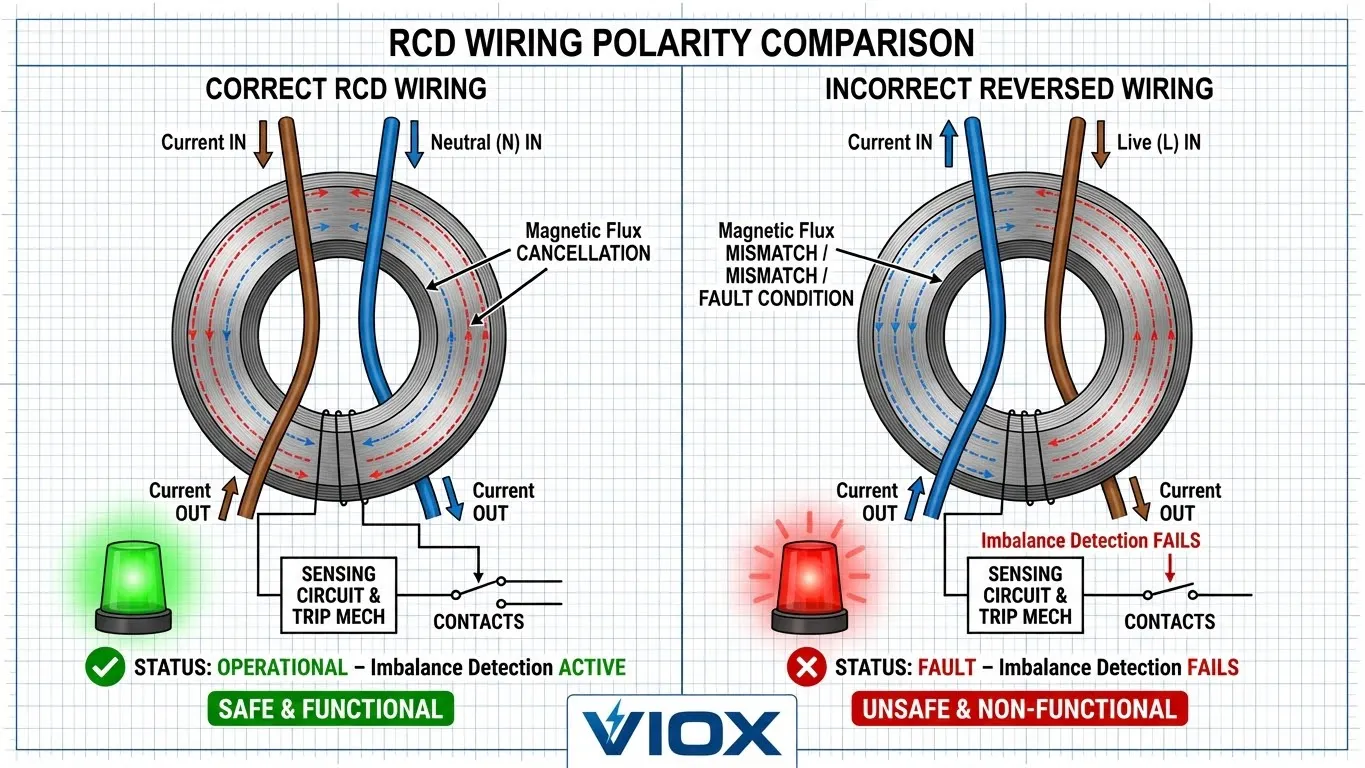
Issue 1: Incorrect Wiring Polarity
Unlike simple electromechanical AC MCBs, many electronic RDC-DD modules are direction-sensitive. They use a fluxgate sensor that expects current to flow from Line to Load.
- Symptom: The tester ramps up to 10mA or more and simply times out.
- Diagnosis: Check the wiring diagram. Did you wire the supply to the output terminals?
- Solution: Reverse the connections to match the “Line/Load” or “In/Out” markings.
Issue 2: Poor Grounding (TT System Issues)
In TT earthing systems (common in some regions), the earth path relies on an electrode rod. If the soil resistance is too high (RA > 100Ω), the tester may not be able to drive the required test current, or it will detect a dangerous touch voltage (>50V) on the PE line and abort the test for safety.
- Solution: Measure ZS (Earth Loop Impedance) first. Refer to Understanding Ground Fault Protection for permissible limits.
Issue 3: RDC-DD Not Enabled
Some “Smart” EV chargers have the RDC-DD functionality integrated into the main PCB, controllable via firmware.
- Symptom: No trip detected.
- Solution: Check the charger’s commissioning app. Ensure “DC Leakage Protection” is toggled ON.
Table 3: Troubleshooting Quick Reference
| Symptom | Probable Cause | Diagnostic Step | Solution |
|---|---|---|---|
| Tester shows “No Trip” | Reversed Polarity | Check wiring direction | Rewire Input/Output correctly |
| “Error 4” / “High Z” | Poor Earth (TT) | Measure RA / ZS | Improve Earth Electrode |
| No Voltage at Outlet | Adapter in State A | Check Adapter LEDs | Turn knob to “State C” (Charge) |
| Trips > 6mA (e.g. 15mA) | Wrong RCD Type | Check Device Label | Ensure it is 6mA RDC-DD, not 30mA AC |
| Instant Trip (0mA) | Existing Fault | Disconnect Output | Locate DC wiring fault downstream |
Conclusion
Testing the 6mA DC trip level is not just a box-ticking exercise; it is the guarantee that your EV charging infrastructure is safe and compliant with IEC 62955 and IEC 61851. Without this specific test, you cannot be certain that the DC leakage protection is active, leaving the upstream Type A RCDs vulnerable to blinding.
Verdict: ✅ Strong Yes.
Professional verification using the ramp test method is the only way to sign off on an installation confidently.
This guide concludes our EV Protection Trilogy. By understanding the system architecture, selecting the correct RCD types, and performing rigorous 6mA DC verification, you ensure your VIOX installations meet the highest safety standards.
For assistance with selecting the right protection devices for your next project, contact the VIOX technical engineering team.
FAQ
Q: Can I use a regular plug-in RCD tester to verify DC protection?
A: No. Standard RCD testers only test AC (Type AC) or pulsating DC (Type A) fault currents. They cannot generate the smooth DC current required to verify the 6mA threshold of an RDC-DD. You must use a tester compliant with IEC 62955.
Q: What is the difference between 6mA DC and 30mA AC trip thresholds?
A: 30mA AC is the threshold for human safety against electrocution (ventricular fibrillation). 6mA DC is an equipment protection threshold—it ensures that DC leakage does not saturate (blind) the upstream Type A RCD, which would stop it from detecting AC faults.
Q: Do I need to test DC protection if the charger has a built-in RDC-DD?
A: Yes. Even built-in devices must be verified during commissioning to ensure they are functioning correctly and have not been damaged during transport or installation. See How to Check RCCB Functionality.
Q: How often should DC protection be retested?
A: IEC 61851 recommends periodic inspection. In commercial environments, we recommend re-testing annually or whenever the unit undergoes maintenance or firmware updates.
Q: Can DC leakage really “blind” a Type A RCD? How?
A: Yes. DC current creates a constant magnetic flux in the RCD’s sensing core. This pushes the core into magnetic saturation. Once saturated, the core can no longer detect the alternating magnetic field caused by an AC earth fault, meaning the RCD won’t trip when it needs to.
Q: What is the difference between RDC-DD and RDC-PD?
A: An RDC-DD (Residual Direct Current Detecting Device) only detects the fault and signals a separate switching device (like a contactor) to open. An RDC-PD (Residual Direct Current Protective Device) is an all-in-one unit that includes the detection and the mechanical circuit breaker/switch in a single housing.
Q: Does temperature affect the 6mA trip threshold?
A: It can. Extreme temperatures can alter the permeability of the sensing core materials. VIOX components are designed with temperature compensation, but it is always best to test within the rated ambient range of the equipment.
