
Principaux enseignements
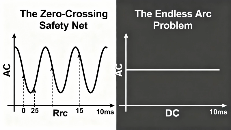
- Facteur de passage par zéro : Le courant alternatif éteint naturellement les arcs aux passages par zéro (100 à 120 fois par seconde), tandis que le courant continu maintient les arcs en permanence.
- Différences de conception : Les sectionneurs CC nécessitent des bobines d'extinction magnétique et des chambres de coupure d'arc profondes, ce qui les rend physiquement plus grands et plus coûteux que les versions CA.
- Déclassement de tension : L'utilisation d'un sectionneur CA pour des applications CC entraîne une baisse significative de la capacité de tension (par exemple, 690 V CA → ~220 V CC).
- Règle de sécurité : N'utilisez jamais un sectionneur de tension alternative pour les systèmes CC tels que le solaire photovoltaïque ou le stockage de batteries afin d'éviter les risques d'incendie et le soudage des contacts.
Le technicien de maintenance ouvre l'interrupteur sectionneur. 600 volts, 32 ampères. Procédure de consignation de routine pour un ensemble solaire sur le toit.
Sauf que l'interrupteur n'était pas conçu pour le courant continu.
À l'intérieur du boîtier, un arc se forme entre les contacts qui se séparent : un pont de plasma brillant et soutenu conduisant 600 V CC à travers l'air ionisé. Dans un système CA, cet arc s'éteindrait naturellement en 10 millisecondes, étouffé au prochain passage à zéro du courant. Mais le courant continu n'a pas de passage à zéro. L'arc se maintient. Les contacts commencent à s'éroder. La température augmente. En quelques secondes, l'isolateur qui était censé assurer une déconnexion sûre devient un conducteur continu à haute tension, exactement au moment où vous avez le plus besoin qu'il soit isolé.
C'est “ Le filet de sécurité du passage à zéro ”— Le courant alternatif l'a, le courant continu ne l'a pas. Et cela change tout dans la façon dont les interrupteurs sectionneurs doivent être conçus, évalués et sélectionnés.

Que sont les interrupteurs isolateurs ?
Un interrupteur d'isolement (également appelé interrupteur sectionneur ou sectionneur) est un dispositif de commutation mécanique conçu pour isoler un circuit électrique de sa source d'alimentation, assurant ainsi la sécurité de la maintenance et des réparations. Réglementé par IEC 60947-3:2020 pour les appareillages basse tension (jusqu'à 1000 V CA et 1500 V CC), les sectionneurs offrent une déconnexion visible (un espace physique que vous pouvez voir ou vérifier) entre les conducteurs sous tension et l'équipement en aval.
Contrairement aux disjoncteurs, les sectionneurs ne sont pas conçus pour interrompre les courants de défaut sous charge. Ce sont des sectionneurs de maintenance. Vous les ouvrez lorsque le circuit est hors tension ou qu'il transporte une charge minimale, créant ainsi un point d'isolation sûr pour les travaux en aval. La plupart des sectionneurs comprennent un mécanisme de verrouillage (moraillon de cadenas ou poignée verrouillable) pour la conformité LOTO (Lockout/Tagout).
Voici ce qui rend la sélection du sectionneur essentielle : la physique de l'interruption d'arc— ce qui se passe dans les microsecondes après l'ouverture de l'interrupteur — est fondamentalement différent pour le courant alternatif et le courant continu. Un sectionneur adéquat pour le service CA peut être totalement inadéquat (et dangereux) pour le service CC, même à une tension plus faible. La plaque signalétique peut indiquer “ 690 V ”, mais il s'agit de 690 V AC. CA. L'utiliser sur une chaîne solaire de 600 V CC ? Vous venez de créer un risque potentiel d'arc électrique.
Ce n'est pas un détail technique mineur ou une marge de sécurité prudente. C'est de la physique. Et comprendre pourquoi nécessite d'examiner ce qui se passe à l'intérieur de chaque interrupteur lorsque les contacts se séparent sous tension.
Pro-Tip #1: N'utilisez jamais un sectionneur conçu pour le courant alternatif pour des applications en courant continu, sauf si sa fiche technique indique explicitement les valeurs nominales de tension/courant en courant continu. Un sectionneur de 690 V CA a généralement une capacité CC de seulement 220 à 250 V CC, soit moins qu'une chaîne solaire à 4 panneaux en circuit ouvert.
Le problème de l'extinction de l'arc : pourquoi le courant continu est différent

Lorsque vous ouvrez un interrupteur sous tension, un arc se forme. C'est inévitable. Lorsque les contacts se séparent, l'espace entre eux est encore suffisamment petit (micromètres, puis millimètres) pour que la tension ionise l'air, créant ainsi un canal de plasma conducteur. Le courant continue de circuler à travers cet arc même si les contacts mécaniques ne se touchent plus.
Pour que l'interrupteur isole véritablement le circuit, cet arc doit être éteint. Et c'est là que le courant alternatif et le courant continu divergent complètement.
CA : Le passage à zéro naturel
Le courant alternatif, comme son nom l'indique, alterne. Un système CA de 50 Hz franchit la tension/le courant zéro 100 fois par seconde. Un système de 60 Hz franchit le zéro 120 fois par seconde. Toutes les 8,33 millisecondes (60 Hz) ou 10 millisecondes (50 Hz), le flux de courant inverse sa direction et passe par zéro.
Au passage à zéro du courant, il n'y a pas d'énergie pour maintenir l'arc. Le plasma se désionise. L'arc s'éteint. Si les contacts se sont suffisamment séparés au cycle suivant, la rigidité diélectrique de l'espace (sa capacité à supporter la tension sans réamorçage) dépasse la tension du système. L'arc ne se réamorce pas. L'isolation est atteinte.
C'est “ Le filet de sécurité du passage à zéro. ” Les sectionneurs CA peuvent compter sur cette interruption naturelle. La conception de leurs contacts, la distance entre les espaces et la géométrie de la chambre d'arc n'ont qu'à garantir que l'arc ne se réamorce pas après le prochain passage à zéro. C'est un problème de conception relativement tolérant.
CC : Le problème de l'arc sans fin
Le courant continu n'a pas de passage à zéro. Jamais. Une chaîne solaire de 600 V CC fournit 600 volts en continu. Lorsque les contacts du sectionneur se séparent et qu'un arc se forme, cet arc est maintenu par une énergie continue. Il n'y a pas de point d'interruption naturelle. L'arc se poursuivra indéfiniment jusqu'à ce que l'une des trois choses suivantes se produise :
- L'espace entre les contacts devient suffisamment grand pour que même l'arc ne puisse pas le franchir (ce qui nécessite une séparation physique beaucoup plus importante qu'en CA)
- L'arc est étiré mécaniquement, refroidi et soufflé à l'aide de champs magnétiques et de cages d'arc
- Les contacts se soudent ensemble en raison du chauffage continu, ce qui annule tout l'objectif de l'isolation
L'option 3 est ce qui se passe lorsque vous utilisez un sectionneur conçu pour le courant alternatif dans un service en courant continu. La vitesse de séparation des contacts et la distance entre les espaces qui fonctionnent bien pour le courant alternatif (car le prochain passage à zéro arrive dans 10 millisecondes) sont insuffisantes pour le courant continu. L'arc se maintient. L'érosion des contacts s'accélère. Dans le pire des cas, les contacts se soudent et vous perdez complètement l'isolation.
Pro-Tip #2: Le courant alternatif franchit le zéro 100 fois par seconde (50 Hz) ou 120 fois (60 Hz) : chaque passage à zéro est une occasion pour l'arc de s'éteindre naturellement. Le courant continu ne franchit jamais le zéro. Ce n'est pas une différence mineure : c'est pourquoi les sectionneurs CC ont besoin de bobines d'extinction magnétique et de cages d'arc profondes que les sectionneurs CA n'ont pas.
Conception du sectionneur CC : Le guerrier de la chambre d'arc
Étant donné que les arcs CC ne s'éteignent pas d'eux-mêmes, les sectionneurs CC doivent forcer l'extinction par des moyens mécaniques agressifs. C'est “ Le guerrier de la chambre d'arc ”— un sectionneur CC est conçu pour la bataille.
Bobines d'extinction magnétique
La plupart des sectionneurs CC intègrent des bobines d'extinction magnétique ou des aimants permanents positionnés près des contacts. Lorsqu'un arc se forme, le champ magnétique interagit avec le courant d'arc (qui est une charge en mouvement), produisant une force de Lorentz qui pousse l'arc loin des contacts et dans la chambre d'extinction d'arc.
Considérez cela comme une main magnétique qui pousse physiquement l'arc loin de l'endroit où il veut rester. Plus vous déplacez l'arc rapidement et loin, plus il se refroidit et s'étire, jusqu'à ce qu'il ne puisse plus se maintenir.
Cages d'arc (plaques de séparation)
Une fois que l'arc est soufflé dans la chambre d'arc, il rencontre des cages d'arc— des réseaux de plaques métalliques (souvent en cuivre) qui divisent l'arc en plusieurs segments plus courts. Chaque segment a sa propre chute de tension. Lorsque la chute de tension totale à travers tous les segments dépasse la tension du système, l'arc ne peut plus se maintenir. Il s'effondre.
Les sectionneurs CC utilisent des conceptions de cages d'arc plus profondes et plus agressives que les sectionneurs CA, car ils ne peuvent pas compter sur les passages à zéro du courant. L'arc doit être éteint de force à plein courant, à chaque fois.
Matériaux de contact à haute teneur en argent
Les arcs CC sont brutaux pour les contacts. L'amorçage continu à pleine tension provoque une érosion et un chauffage rapides. Pour résister à cela, les sectionneurs CC utilisent des matériaux de contact avec une teneur en argent plus élevée (souvent des alliages argent-tungstène ou argent-nickel) qui résistent mieux à la soudure et à l'érosion que les contacts en cuivre ou en laiton courants dans les sectionneurs CA.
Le résultat ? Un sectionneur CC de 1000 V CC à 32 A est physiquement plus grand, plus lourd, plus complexe et coûte 2 à 3 fois plus cher qu'un sectionneur CA de même calibre. Ce n'est pas une tarification arbitraire : c'est le coût d'ingénierie de l'extinction forcée de l'arc sans passage à zéro.
Pro-Tip #3: Pour les systèmes photovoltaïques, vérifiez toujours que la tension nominale CC du sectionneur dépasse la tension maximale en circuit ouvert (Voc) de votre chaîne à la température la plus basse prévue. Une chaîne de 10 panneaux de modules de 400 W peut atteindre 500 à 600 V CC à -10 °C, ce qui dépasse la capacité de nombreux sectionneurs “ compatibles CC ”. Consultez également notre guide sur Connexion des sectionneurs CC pour connaître les pratiques de câblage sûres.

Conception du sectionneur CA : Surfer sur le passage à zéro
Les sectionneurs CA sont, en comparaison, simples. Ils n'ont pas besoin de bobines d'extinction magnétique (bien que certains en incluent pour une interruption plus rapide). Ils n'ont pas besoin de cages d'arc profondes. Ils n'ont pas besoin de matériaux de contact exotiques.
Pourquoi ? Parce que le passage à zéro fait l'essentiel du travail. Le travail du sectionneur CA n'est pas d'éteindre de force l'arc, mais de s'assurer que l'arc ne se réamorce pas après l'interruption naturelle du passage à zéro.
- Distance d'espacement suffisante : Généralement 3 à 6 mm pour le courant alternatif basse tension, selon la tension et le degré de pollution
- Confinement d'arc de base : Barrières isolantes simples pour empêcher le cheminement d'arc sur les surfaces
C'est tout. Les sectionneurs CA comptent sur la forme d'onde pour faire le gros du travail. La conception mécanique doit juste suivre le rythme. Pour des applications spécifiques comme les moteurs triphasés, consultez notre Guide complet des sectionneurs triphasés.
La pénalité de réduction de tension
Voici une surprise qui surprend de nombreux ingénieurs : si vous doit utilisez un sectionneur conçu pour AC pour du DC (ce que vous ne devriez pas faire, mais hypothétiquement), sa capacité de tension DC est considérablement inférieure à sa tension nominale AC. C'est “La pénalité de réduction de tension.”
Un schéma typique :
- Tension nominale de 690V AC → capacité d'environ 220-250V DC
- Tension nominale de 400V AC → capacité d'environ 150-180V DC
- Tension nominale de 230V AC → capacité d'environ 80-110V DC
Pourquoi une réduction aussi sévère ? Parce que la tension d'arc DC est fondamentalement différente de la tension d'arc AC. Les fabricants en tiennent compte en réduisant considérablement la tension nominale DC.
Pour les applications solaires photovoltaïques, c'est “Le piège des chaînes PV.” Un panneau solaire courant de 400W a une tension en circuit ouvert (Voc) d'environ 48-50V en STC. Chaîne de 10 panneaux ensemble : 480-500V. Mais la Voc augmente à des températures plus basses. Un sectionneur AC de 400V avec une tension nominale DC de 180V ? Complètement inadéquat.
Pro-Tip #4: Les sectionneurs sont conçus pour la commutation à vide ou à charge minimale : ce sont des sectionneurs de maintenance, pas des protections contre les surintensités. Pour les environnements nécessitant une protection contre les intempéries, assurez-vous de bien comprendre Indices de protection IP pour les sectionneurs.

Sectionneur DC vs AC : Comparaison des spécifications clés
| Spécification | Isolateur CA | Isolateur DC |
|---|---|---|
| Mécanisme d'extinction de l'arc | Passage à zéro de courant naturel (100-120 fois/sec) | Extinction mécanique forcée (soufflage magnétique + chambres d'arc) |
| Intervalle de contact requis | 3-6mm (varie selon la tension) | 8-15mm (intervalle plus grand pour la même tension) |
| Conception de la chambre d'arc | Minimal ou nul | Plaques de séparation profondes, géométrie agressive |
| Soufflage magnétique | Optionnel (pour une interruption rapide) | Obligatoire (aimants permanents ou bobines) |
| Matériau de contact | Cuivre, laiton, alliages standard | Teneur élevée en argent (alliages Ag-W, Ag-Ni) |
| Exemple de tension nominale | 690V AC | 1000V DC ou 1500V DC |
| Exemple de courant nominal | 32A, 63A, 125A typique | 16A-1600A (plage plus large pour PV/ESS) |
| Les Applications Typiques | Contrôle de moteur, CVC, distribution AC industrielle | Solaire PV, stockage de batterie, recharge de VE, microgrids DC |
| Normes | IEC 60947-3:2020 (catégories d'utilisation AC) | IEC 60947-3:2020 (catégories d'utilisation DC : DC-21B, DC-PV2) |
| De Taille Et De Poids | Compact, léger | Plus grand, plus lourd (2-3× la taille pour le même courant nominal) |
| Coût | Inférieur (de base) | 2-3× plus cher |
| Durée de l'arc à l'ouverture | <10ms (jusqu'au prochain passage à zéro) | Continu jusqu'à l'extinction mécanique |
Principaux enseignements : La “pénalité de coût de 2 à 3×” pour les sectionneurs DC n'est pas une majoration de prix - elle reflète la taxe de physique fondamentale de l'extinction des arcs sans passages à zéro.
Quand utiliser des sectionneurs DC vs AC
La décision ne concerne pas la préférence ou l'optimisation des coûts - il s'agit d'adapter la capacité d'extinction d'arc du sectionneur au type de courant de votre système.
Utilisez des sectionneurs DC pour :
1. Systèmes solaires photovoltaïques (PV)
Chaque chaîne CC de panneaux solaires nécessite une isolation entre les panneaux et l'onduleur. Les tensions des chaînes atteignent couramment 600 à 1000 V CC. Recherchez la catégorie d'utilisation CEI 60947-3 DC-PV2 spécialement conçue pour les tâches de commutation photovoltaïque. Consultez notre guide sur Valeurs nominales de tension des boîtiers de raccordement solaires pour plus de détails.
2. Systèmes de stockage d'énergie par batterie (ESS)
Les bancs de batteries fonctionnent à des tensions DC allant de 48V à 800V+. Une isolation est requise entre les modules de batterie et les onduleurs.
3. Infrastructure de recharge de VE
Les chargeurs rapides DC fournissent 400-800V DC directement aux batteries des véhicules.
4. Microgrids DC et centres de données
Les centres de données utilisent de plus en plus la distribution 380V DC pour réduire les pertes de conversion.
5. Distribution DC marine et ferroviaire
Les navires et les trains utilisent la distribution DC (24V, 48V, 110V, 750V) depuis des décennies.
Utilisez des sectionneurs AC pour :
1. Circuits de commande de moteur
Isolation pour les moteurs à induction AC, les systèmes CVC et les pompes.
Distribution AC des bâtiments
Isolation pour les panneaux d'éclairage et les charges générales du bâtiment.
Panneaux de commande AC industriels
Armoires de commande de machines avec Contacteurs à courant alternatif et automates programmables (PLC).
La règle critique
Si la tension de votre système est continue (même 48 V CC), utilisez un sectionneur de qualité CC. La physique de l'arc ne se soucie pas du niveau de tension ; elle se soucie du type de forme d'onde. Un arc de 48 V CC peut toujours se maintenir et provoquer le soudage des contacts dans un interrupteur uniquement CA.

Guide de sélection : Méthode en 4 étapes pour les sectionneurs CC
Étape 1 : Calculer la tension maximale du système
Pour Solaire photovoltaïque : Calculer la Voc de la chaîne à la température ambiante la plus basse prévue. La Voc augmente d'environ 0,3 à 0,4 % par °C en dessous de 25 °C.
- Exemple : chaîne de 10 panneaux, Voc = 49 V/panneau à STC. À -10 °C : 49 V × 1,14 (facteur de température) × 10 panneaux = Tension nominale minimale du sectionneur de 559 V CC
Pro-Tip: Toujours spécifier une tension nominale du sectionneur d'au moins 20 % supérieure à la tension maximale calculée du système pour une marge de sécurité.
Étape 2 : Déterminer le courant nominal
Pour Solaire photovoltaïque : Utiliser le courant de court-circuit de la chaîne (Isc) × facteur de sécurité de 1,25.
Étape 3 : Vérifier la catégorie d'utilisation
Vérifier la fiche technique pour la catégorie d'utilisation CEI 60947-3 : DC-21B pour les circuits CC généraux, DC-PV2 spécifiquement pour la commutation CC photovoltaïque.
Étape 4 : Confirmer le pouvoir de coupure en court-circuit (le cas échéant)
La plupart des sectionneurs sont conçus pour la commutation à vide ou à charge minimale. Pour la commutation régulière de charge ou l'interruption de défaut, spécifiez un Disjoncteur CC à la place.
Pro-Tip #5: Les sectionneurs CC coûtent 2 à 3 fois plus cher que les sectionneurs CA équivalents, car ils nécessitent des matériaux de contact fondamentalement différents, des systèmes de soufflage magnétique et des chambres d'extinction d'arc profondes.
Foire Aux Questions
Puis-je utiliser un isolateur CA pour les applications CC ?
Non, généralement vous ne pouvez pas. Les sectionneurs CA comptent sur le “ passage par zéro ” du courant alternatif pour éteindre les arcs électriques. Le courant continu n'a pas de passage par zéro, ce qui signifie que les arcs peuvent se maintenir indéfiniment dans un interrupteur CA, entraînant une surchauffe, un incendie et le soudage des contacts.
Pourquoi les sectionneurs CC sont-ils plus grands que les sectionneurs CA ?
Les sectionneurs CC nécessitent des composants internes plus grands, tels que des bobines d'extinction magnétique et des chambres de coupure d'arc plus profondes (plaques de séparation), pour forcer mécaniquement l'extinction de l'arc. Ils nécessitent également des espaces de contact plus larges pour empêcher le réamorçage de l'arc.
Quelle est la différence entre un sectionneur CC et un disjoncteur CC ?
Un sectionneur CC est conçu principalement pour la déconnexion de maintenance (isolation du circuit) et est généralement actionné hors charge. Un Disjoncteur CC offre une protection automatique contre les surcharges et les courts-circuits et est conçu pour interrompre les courants de défaut sous charge.
Conclusion : La physique n'est pas facultative
La différence entre les sectionneurs CC et CA n'est pas une question de valeurs nominales, de coût ou de préférence. C'est de la physique.
Les sectionneurs CA reposent sur “ Le filet de sécurité du passage à zéro ”. Les sectionneurs CC sont confrontés à “ Le problème de l'arc sans fin ”. L'arc se maintiendra indéfiniment à moins que l'interrupteur ne force l'extinction par le biais de bobines de soufflage magnétique et de goulottes d'arc profondes.
Lorsque vous spécifiez un sectionneur pour une chaîne solaire photovoltaïque ou un stockage de batterie, vous sélectionnez un système d'extinction d'arc. Utilisez le mauvais, et vous risquez un arc soutenu et un incendie. La règle est simple : si votre tension est continue, utilisez un sectionneur de qualité CC.
La physique n'est pas négociable. Choisissez en conséquence.
Besoin d'aide pour choisir des sectionneurs CC pour votre projet solaire photovoltaïque ou de stockage de batterie ? Contactez notre équipe d'ingénierie d'application pour obtenir des conseils techniques sur les solutions de commutation CC conformes à la norme CEI 60947-3.
