En esta página
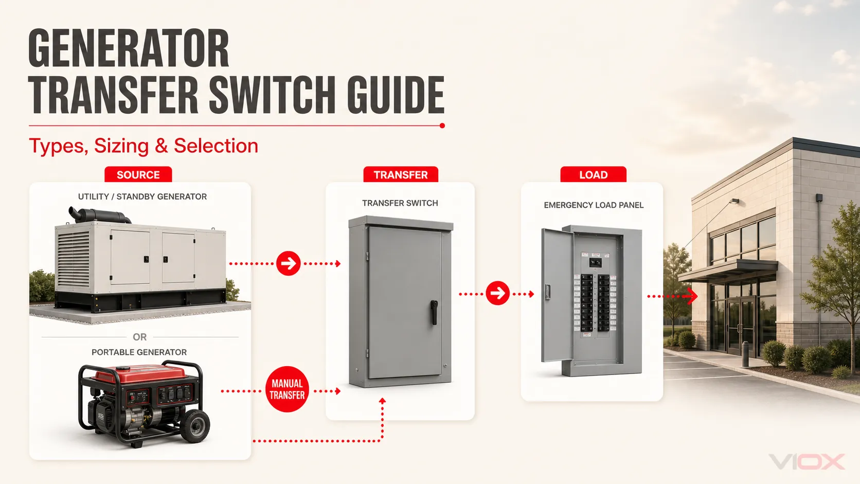
Un interruptor de transferencia de generador conecta una carga ya sea a la fuente de red normal o a un generador, evitando que ambas fuentes se conecten de manera insegura. Para la mayoría de los proyectos, la primera decisión es sencilla: un generador portátil normalmente utiliza un dispositivo de transferencia manual aprobado, mientras que un generador de reserva instalado permanentemente utiliza normalmente un interruptor de transferencia automática (ATS). El equipo correcto sigue dependiendo de los circuitos que se van a respaldar, la tensión y fase del sistema, el tratamiento del neutro, los valores nominales de corriente y falla, y los controles del generador.
Regla de selección: elija la arquitectura de transferencia antes de elegir un valor nominal de amperaje. Comience con el tipo de generador y el alcance de la carga; luego verifique los valores nominales eléctricos, la configuración del neutro, el método de transición, la compatibilidad de control y la certificación regional.
Selección rápida: ¿Qué arquitectura de transferencia de generador se ajusta?
| Generador y alcance de la carga | Arquitectura de transferencia típica | Qué debe verificarse |
|---|---|---|
| Generador portátil, circuitos seleccionados | Panel de transferencia manual o interruptor de transferencia manual listado/aprobado con una entrada compatible | Receptáculo del generador, capacidad nominal del cable/entrada, demanda de carga seleccionada, disposición del neutro, enclavamiento mecánico |
| Generador portátil, acceso al panel principal | Dispositivo de transferencia manual para todo el panel o una arquitectura de enclavamiento de panel aprobada | Configuración del servicio, salida del generador, gestión de carga, compatibilidad del panel, aceptación del código local |
| Generador de reserva, circuitos seleccionados | ATS que alimenta un panel de carga de emergencia | Contactos de arranque del generador, retardos de transferencia, demanda de carga, coordinación de dispositivos de protección |
| Generador de reserva, edificio completo | ATS para todo el edificio, a veces equipo de transferencia en la acometida | Corriente de servicio, capacidad del generador, desconexión de carga, capacidad de cortocircuito, disposición de puesta a tierra y neutro |
| Generador industrial trifásico | ATS trifásico o equipo de conmutación de transferencia (TSE) | Tensión, frecuencia, secuencia de fases, disposición 3P/4P, categoría de utilización, WCR/SCCR, controles |
Estos son puntos de partida de arquitectura, no sustitutos de las instrucciones del generador, del interruptor de transferencia y de la instalación. Un diseñador o instalador cualificado debe verificar el sistema completo conforme a las normas adoptadas localmente.
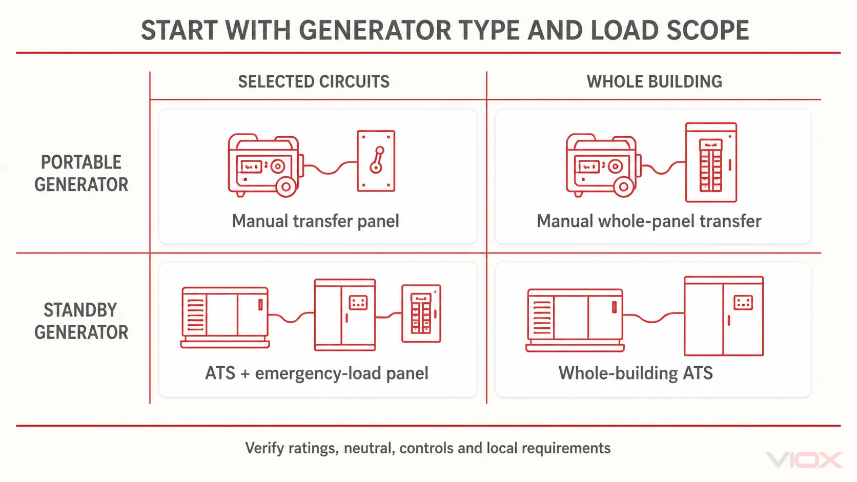
Por qué el interruptor de transferencia es una decisión de sistema
Un interruptor de transferencia de generador realiza dos funciones relacionadas:
- Selecciona qué fuente alimenta la carga conectada.
- Evita la conexión involuntaria o el retorno de energía entre la fuente normal y la del generador.
Esa segunda función es crítica. Un generador portátil conectado a través de un cable improvisado o una disposición de panel no aprobada puede energizar conductores que se espera que estén aislados. Una disposición de transferencia adecuada utiliza conmutación enclavada mecánica o eléctricamente para que las rutas de la fuente normal y la alternativa no puedan cerrarse juntas, a menos que el equipo esté específicamente diseñado y controlado para una operación de transición cerrada.
El interruptor de transferencia no crea capacidad de generación. Tampoco proporciona necesariamente protección contra sobrecorriente, sincronización de fuentes, desconexión de carga, desconexión de servicio o control del generador, a menos que esas funciones estén explícitamente incluidas en el equipo. Por lo tanto, la especificación debe describir todo el trayecto:
Fuente de la red eléctrica -> equipo de transferencia -> distribución de respaldo -> cargas conectadas
La conexión del generador, los dispositivos de protección, la disposición de puesta a tierra y el cableado de control se sitúan alrededor de ese trayecto y deben coordinarse con él.
Paso 1: Comience con la generación portátil o de reserva
Generador portátil: la transferencia manual suele ser el punto de partida práctico
Un generador portátil se coloca en posición y es puesto en marcha por un operador. Por lo tanto, su equipo de transferencia es comúnmente manual. Los productos residenciales pueden combinar un mecanismo de transferencia manual con circuitos derivados seleccionados, o pueden proporcionar acceso a un panel más grande mientras requieren que el operador desconecte cargas.
No asuma que todo generador portátil funciona con todo interruptor de transferencia manual. Confirme:
- voltaje, fase, frecuencia y salida continua máxima del generador;
- configuración del receptáculo y si se requiere una entrada de alimentación compatible;
- si el neutro del generador está conectado a tierra o flotante;
- compatibilidad con GFCI cuando sea relevante;
- compatibilidad del interruptor de transferencia o del panel;
- qué cargas pueden energizarse sin exceder la capacidad del generador.
La guía de transferencia manual de Generac, por ejemplo, establece que el equipo de transferencia manual evita el retroceso de energía (backfeed) y permite la gestión escalonada de cargas, pero también señala que la compatibilidad depende del modelo. Esta es una ilustración útil de las comprobaciones requeridas, no una regla universal del producto.
Generador de reserva: el control automático suele ser parte del sistema
Un generador de reserva instalado permanentemente se empareja normalmente con un ATS. El controlador monitorea la fuente normal, inicia el arranque del generador tras un fallo calificado de la fuente, espera hasta que el voltaje y la frecuencia del generador sean aceptables, transfiere la carga y, posteriormente, realiza la transferencia de retorno tras la recuperación del suministro eléctrico. También pueden estar presentes funciones de enfriamiento y reintento.
El ATS y el generador deben compartir una interfaz de control compatible. Un interruptor con contactos de potencia adecuados puede resultar inutilizable si su señal de arranque, voltaje de control, método de detección o funciones de temporización no coinciden con el controlador del generador.
Para una comparación más detallada de los sistemas dependientes del operador y los sistemas automáticos, consulte Conmutador de transferencia manual frente a automático. Para la secuencia de operación automática, consulte Cómo funciona un conmutador de transferencia automática.
Paso 2: Decida qué cargas recibirán energía del generador
Respaldo de circuitos seleccionados
Un panel de cargas de emergencia contiene solo los circuitos destinados a funcionar con el generador. Esta arquitectura suele ser más fácil de mantener dentro de la capacidad del generador porque las cargas no esenciales permanecen fuera de la sección respaldada.
Las cargas seleccionadas típicas pueden incluir controles, iluminación, refrigeración, comunicaciones, bombas u otros circuitos esenciales definidos por el proyecto. La lista real debe elaborarse a partir de la prioridad operativa y la demanda medida o calculada, no de una lista de verificación genérica de aparatos.
Transferencia de todo el edificio o de todo el panel
Un dispositivo de transferencia para todo el edificio pone el sistema eléctrico de distribución principal a disposición del generador, pero eso no no significa que el generador pueda hacer funcionar todas las cargas simultáneamente. Una conexión de generador portátil de 30 A o 50 A puede coexistir con un arreglo de transferencia de servicio de red de 200 A porque esas cifras describen partes diferentes del sistema. El operador o un sistema automático de gestión de carga debe mantener la demanda del generador dentro de su capacidad.
Esta distinción evita dos errores comunes:
- dimensionar el generador basándose únicamente en la capacidad nominal del servicio de red;
- asumiendo que un interruptor de transferencia para toda la casa garantiza el funcionamiento simultáneo de toda la casa.
Cuando existan arranques de motores, compresores, bombas, calefacción eléctrica u otras cargas grandes, considere su comportamiento de arranque y de carga escalonada, así como la demanda en estado estacionario.
Paso 3: Separe las cinco clasificaciones que los compradores suelen confundir
La frase “necesito un interruptor de transferencia de 200 A” no es una especificación completa. Al menos cinco niveles de clasificación pueden ser importantes.
| Nivel de clasificación | Lo que describe | Pregunta de verificación típica |
|---|---|---|
| Clasificación de salida del generador | Corriente o potencia disponible de la fuente alternativa | ¿Qué carga continua y transitoria puede suministrar el generador a la tensión y frecuencia requeridas? |
| Capacidad nominal de la entrada, enchufe, cable o interruptor automático del generador | Trayectoria de conexión para un generador portátil | ¿Están coordinados la configuración del conector, la capacidad nominal del conductor y el dispositivo de protección? |
| Corriente continua del interruptor de transferencia | Corriente que el equipo de transferencia puede transportar bajo sus condiciones marcadas | ¿Cubre la carga de diseño y la categoría de utilización aplicable sin depender de un margen inventado? |
| Capacidad nominal del servicio de red o alimentador | Capacidad de la trayectoria de la fuente normal y la distribución asociada | ¿El interruptor está ubicado en la entrada de servicio o aguas abajo, y qué corriente debe transportar la trayectoria normal? |
| Capacidad de cortocircuito | Capacidad del equipo para soportar y/o cerrar ante la corriente de falla disponible bajo la protección especificada | ¿El WCR o SCCR marcado es adecuado para la corriente de falla disponible y el dispositivo de protección aguas arriba especificado? |
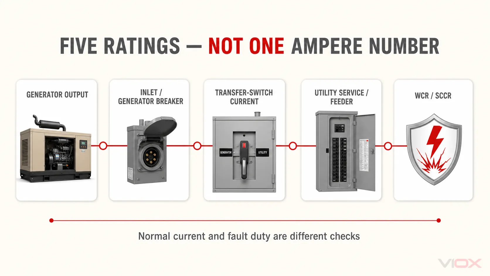
La corriente continua no es lo mismo que la capacidad del generador
Seleccione el equipo de transferencia de acuerdo con la corriente que debe transportar en su posición instalada y las condiciones marcadas por el fabricante. Luego, realice un cálculo de carga del generador por separado. No aplique un margen porcentual universal sin un código, instrucción del fabricante o especificación del proyecto que lo justifique.
La clasificación de falla no puede inferirse de la clasificación de amperaje
Un interruptor de transferencia de 100 A no es automáticamente adecuado para cada alimentador de 100 A. La corriente de cortocircuito disponible en el punto de instalación puede ser mucho mayor que la corriente de carga normal. En aplicaciones norteamericanas, los interruptores de transferencia pueden tener clasificaciones de soportabilidad y cierre (WCR) que dependen de un dispositivo de protección contra sobrecorriente aguas arriba específico o de condiciones de tiempo corto definidas. Los proyectos IEC requieren de manera similar que las clasificaciones TSE especificadas y la coordinación del dispositivo de protección coincidan con el conjunto y el estudio de fallas.
Para la relación de protección, utilice la dedicada Guía de coordinación de ATS e interruptor automático.
Paso 4: Haga coincidir la tensión, la fase, los polos y el tratamiento del neutro
El interruptor de transferencia debe coincidir tanto con las fuentes como con la carga:
- tensión operativa nominal;
- frecuencia de AC;
- configuración monofásica o trifásica;
- número de conductores de fase conmutados;
- si el neutro permanece sólido o es conmutado;
- método de puesta a tierra y conexión equipotencial.
El número de polos no es solo una cuestión de conteo de fases
Un sistema monofásico de línea a línea y neutro puede utilizar dos conductores de fase conmutados con un neutro sólido o un tercer polo conmutado para el neutro. Un sistema trifásico de cuatro hilos puede utilizar tres fases conmutadas con un neutro sólido o un cuarto polo con capacidad nominal completa.
La decisión sobre el neutro no puede tomarse basándose en que “monofásico equivale a 2P” o “trifásico equivale a 4P”. Depende de si el generador se trata como un sistema derivado por separado, de la conexión neutro-tierra del generador, del método de puesta a tierra del sistema, de los dispositivos de protección y de las normas adoptadas localmente. Un tratamiento incorrecto del neutro puede crear rutas paralelas entre el neutro y tierra o interferir con la protección contra fallas a tierra.
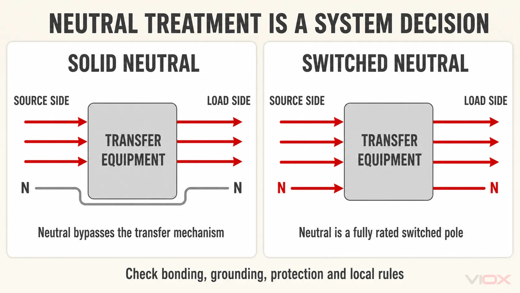
Utilice las instrucciones del generador y del equipo de transferencia, además de la autoridad competente o el ingeniero del proyecto. El artículo especializado ATS monofásico frente a trifásico: 2P, 3P o 4P explica la decisión sobre los polos con más detalle.
Paso 5: Verificar la lógica de arranque del generador y de aceptación de la fuente
La transferencia automática requiere más que contactos de potencia motorizados. Confirme la cadena de control completa:
- Detección de la fuente normal: umbrales de tensión y frecuencia, pérdida de fase, secuencia de fases y retardos ajustables cuando sea necesario.
- Comando de arranque del generador: contacto seco u otra interfaz esperada por el controlador del generador.
- Aceptación de la fuente de emergencia: el ATS debe transferir solo después de que la fuente del generador sea estable y esté dentro de los límites configurados.
- Retardos de transferencia y retransferencia: suficientes para evitar operaciones innecesarias mientras se cumple con la tolerancia a cortes de la carga.
- Enfriamiento del motor: operación continua sin carga cuando lo requiera el fabricante del generador.
- Alarmas de fallo y controles manuales: indicaciones, contactos remotos y funciones de prueba segura requeridas por el proyecto.
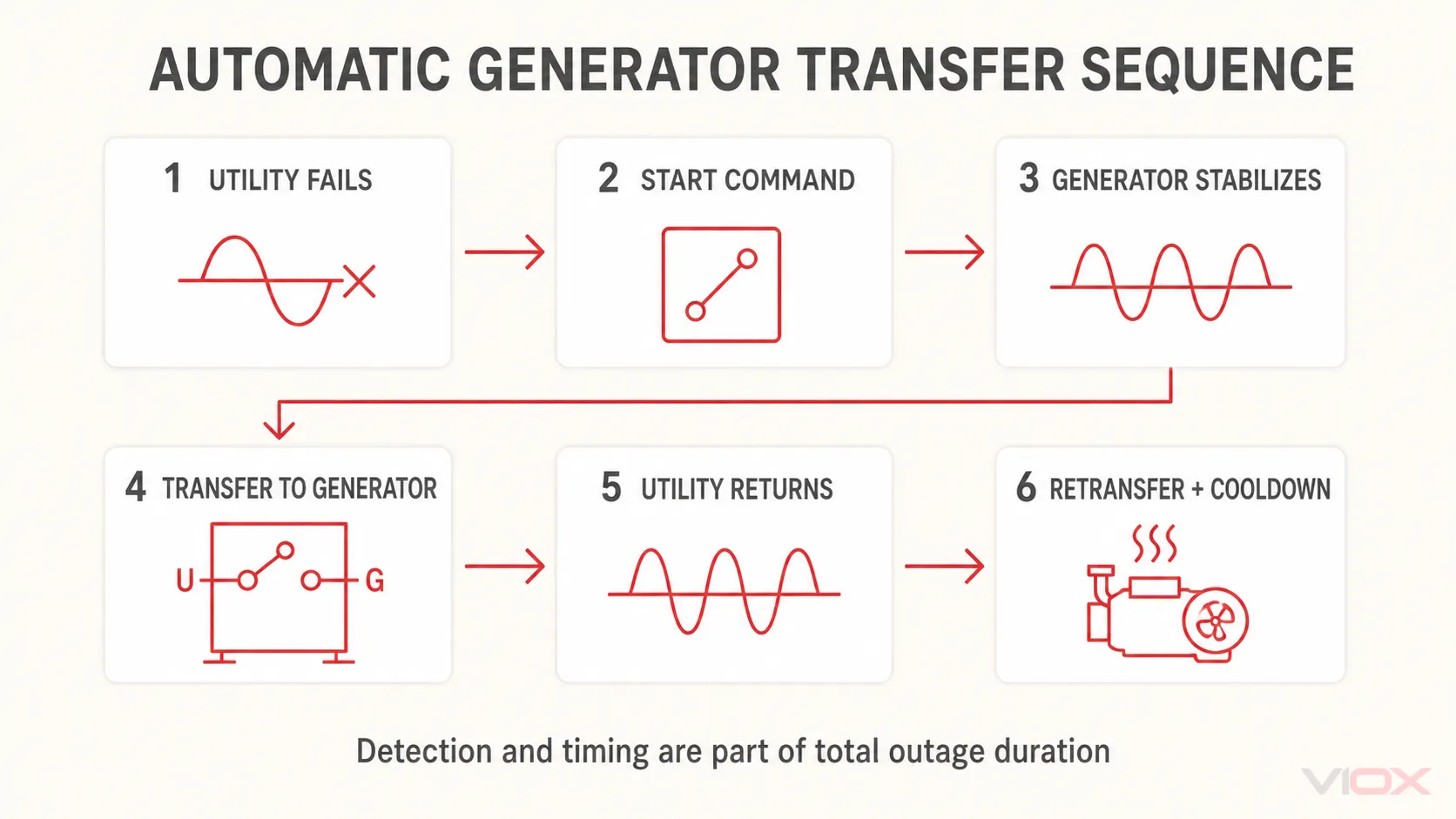
Registre la tensión de control, las funciones de los bornes, el tipo de contacto y la lógica de señal en la solicitud de cotización (RFQ). El término “arranque a dos hilos” se utiliza a menudo como abreviatura, pero el comportamiento de los bornes debe verificarse en la documentación de ambos fabricantes.
Paso 6: Elija el método de transición sin especificarlo en exceso
Para la mayoría de las aplicaciones de generadores, transición abierta es el punto de partida normal. Es de tipo «abrir antes de cerrar»: la carga se desconecta de una fuente antes de conectarse a la otra. Esto evita la superposición intencionada de fuentes, pero la carga sigue experimentando el intervalo de arranque y aceptación del generador, además del intervalo de conmutación.
La transición cerrada pone brevemente en paralelo las fuentes aceptables durante la transferencia. Requiere sincronización de fuentes, controles adecuados, equipos clasificados específicamente para esa operación y, a menudo, coordinación o aprobación de la compañía eléctrica. No elimina la interrupción inicial mientras arranca un generador de reserva detenido.
La transición retardada y la transferencia en fase responden a requisitos específicos de motores, tensión residual o procesos. Especifíquelos solo después de definir el comportamiento de la carga y las condiciones de la fuente. Véase ATS de transición abierta frente a cerrada para la comparación dedicada.
Paso 7: Comprobar la función de entrada de servicio y las normas regionales
proyectos IEC
IEC 60947-6-1:2026 cubre equipos de conmutación de transferencia de baja tensión de hasta 1,000 V AC o 1,500 V DC. Su alcance incluye TSE de operación manual (MTSE), TSE de operación remota (RTSE), TSE automático (ATSE), equipos de bypass/aislamiento, ATSE de transición cerrada y otras categorías definidas.
Especifique la categoría de utilización aplicable, los valores nominales operativos y de cortocircuito, el número de polos, la secuencia de transferencia y las condiciones ambientales. El cumplimiento corresponde al equipo de transferencia marcado completo; una combinación de interruptores no relacionados construida en campo no es automáticamente equivalente a un TSE probado por tipo.
Proyectos en Norteamérica
UL Solutions identifica las categorías UL 1008 para interruptores de transferencia automáticos y no automáticos. Si el interruptor de transferencia sirve como equipo de acometida, debe ser específicamente adecuado para esa función y aplicarse bajo el código eléctrico adoptado localmente. Una ubicación en todo el edificio no hace automáticamente que cada ATS tenga una clasificación de entrada de servicio.
Las especificaciones norteamericanas también deben verificar el WCR marcado, el dispositivo de protección aguas arriba permitido, la clasificación de la envolvente, la configuración del neutro y si las funciones requeridas de desconexión de servicio y sobrecorriente son integrales o separadas.
Otros mercados pueden adoptar normas IEC con desviaciones nacionales o utilizar diferentes sistemas de certificación. Indique el país de destino y la aprobación requerida en la solicitud de cotización (RFQ) en lugar de asumir que un certificado cubre todos los mercados.
Lista de verificación de especificaciones para interruptores de transferencia de generador
Utilice esta lista de verificación antes de comparar productos o solicitar una cotización.
| Entrada | Información a proporcionar |
|---|---|
| Fuentes | Red-generador, generador-generador u otro par definido |
| Generador | Portátil o estacionario; fabricante/modelo; kW/kVA; tensión; fase; frecuencia; conexión de neutro |
| Alcance de la carga | Circuitos seleccionados, panel de emergencia, alimentador o edificio completo |
| Datos de carga | Demanda calculada, motor más grande, método de arranque, cargas escalonadas, interrupción aceptable |
| Trayectoria normal | Tensión y corriente de servicio o del alimentador; función de entrada de servicio si corresponde |
| Operación de transferencia | Manual, operado remotamente o automático |
| Polos y neutro | Fases conmutadas; neutro sólido o conmutado; disposición de puesta a tierra |
| Transición | Abierta, retardada, en fase o cerrada cuando esté justificado |
| Deber de falla | Corriente de falla disponible y WCR/SCCR requerido; detalles del dispositivo de protección aguas arriba |
| Controles | Interfaz de arranque del generador, tensión de control, umbrales de detección, retardos, alarmas, comunicaciones |
| Instalación | Interior/exterior, requisitos de envolvente/IP/NEMA, altitud, temperatura, condiciones de contaminación/corrosión |
| Normas | Mercado de destino, requisito IEC/UL o nacional, especificación del proyecto |
| Mantenimiento | Medios de accionamiento manual, modo de prueba, requisito de bypass/aislamiento, contactos de reserva y accesibilidad |
Una secuencia de decisión práctica
- Defina los circuitos que deben permanecer alimentados.
- Confirme la salida del generador y la capacidad de escalonamiento de carga.
- Elija una arquitectura portátil/manual o de reserva/automática.
- Establezca las rutas de corriente normal y del generador por separado.
- Resuelva la tensión, fase, número de polos, neutro y puesta a tierra.
- Verifique la capacidad de cortocircuito y la coordinación de los dispositivos de protección.
- Haga coincidir los controles de arranque del generador y de detección.
- Confirme el método de transición, la envolvente, el entorno y las aprobaciones regionales.
- Envíe todas las entradas como una única solicitud de presupuesto (RFQ) a nivel de sistema.
Dónde encajan los interruptores de transferencia VIOX
VIOX suministra interruptores de transferencia automáticos para aplicaciones definidas de baja tensión con doble fuente. La gama actual de ATS VIOX no debe interpretarse como un catálogo de kits de entrada para generadores portátiles, paneles de transferencia residenciales manuales o equipos de acometida de América del Norte.
Para una consulta sobre ATS, envíe el diagrama de la fuente, la tensión, la fase, la corriente de carga, el requisito de polos y neutro, la información sobre la corriente de falla disponible, la interfaz de arranque del generador, el tiempo de transferencia, las condiciones de la envolvente y la norma de destino a [email protected]. VIOX puede entonces evaluar si un modelo documentado se ajusta a la aplicación; si no es así, la arquitectura no debe forzarse en torno a un interruptor inadecuado.
Preguntas Frecuentes
¿Necesito un interruptor de transferencia para un generador portátil?
Si un generador portátil va a alimentar circuitos de un edificio con cableado permanente, generalmente requiere un dispositivo de transferencia o un sistema de enclavamiento aprobado que evite el retorno de corriente (backfeed). La arquitectura exacta permitida depende del panel, del generador y de las normativas locales. Las cargas conectadas individualmente mediante cable son un caso distinto y deben seguir las instrucciones del fabricante del generador.
¿Se puede conectar un generador de 50 A a través de un interruptor de transferencia para toda la casa de 200 A?
Potencialmente, ya que las cifras pueden describir diferentes trayectorias de corriente: 50 A en la conexión del generador y 200 A en la trayectoria de la red eléctrica o de servicio. El equipo de transferencia debe estar diseñado y marcado para esa configuración, y las cargas del lado del generador deben gestionarse de modo que no excedan la capacidad del generador.
¿Un interruptor de transferencia para toda la casa requiere un generador para toda la casa?
No. “Toda la casa” puede describir el acceso a todo el panel de distribución, no la capacidad de hacer funcionar todas las cargas simultáneamente. El generador y el plan de gestión de cargas determinan qué cargas pueden funcionar juntas.
¿Debe conmutarse el neutro del generador?
Depende del diseño de la puesta a tierra y la conexión equipotencial, incluyendo si el generador es una fuente derivada por separado. No tome la decisión basándose únicamente en el número de fases. Siga las instrucciones del generador y del interruptor de transferencia, y haga que el diseño sea verificado bajo el código aplicable.
¿Es instantáneo un interruptor de transferencia automática?
No. Un sistema de generador de reserva debe detectar el corte, arrancar el motor, estabilizar la tensión y la frecuencia, y luego realizar la transferencia. El mecanismo de conmutación puede operar rápidamente, pero el tiempo total de corte incluye los retardos de arranque y calificación del generador.
¿Se puede utilizar un ATS con cualquier generador?
No. Las especificaciones eléctricas pueden coincidir mientras que los contactos de arranque, la tensión de control, la lógica de detección, la disposición del neutro o la certificación no lo hagan. Verifique el ATS y el generador como un sistema coordinado.
Fuentes y normas
- IEC 60947-6-1:2026: Equipos de conmutación de transferencia
- UL Solutions: Servicios de certificación y evaluación de interruptores
- Eaton: Fundamentos de los interruptores de transferencia automática
- Generac: ¿Qué es un interruptor de transferencia manual?
- Generac: Interruptores de transferencia manual para toda la casa