On this page
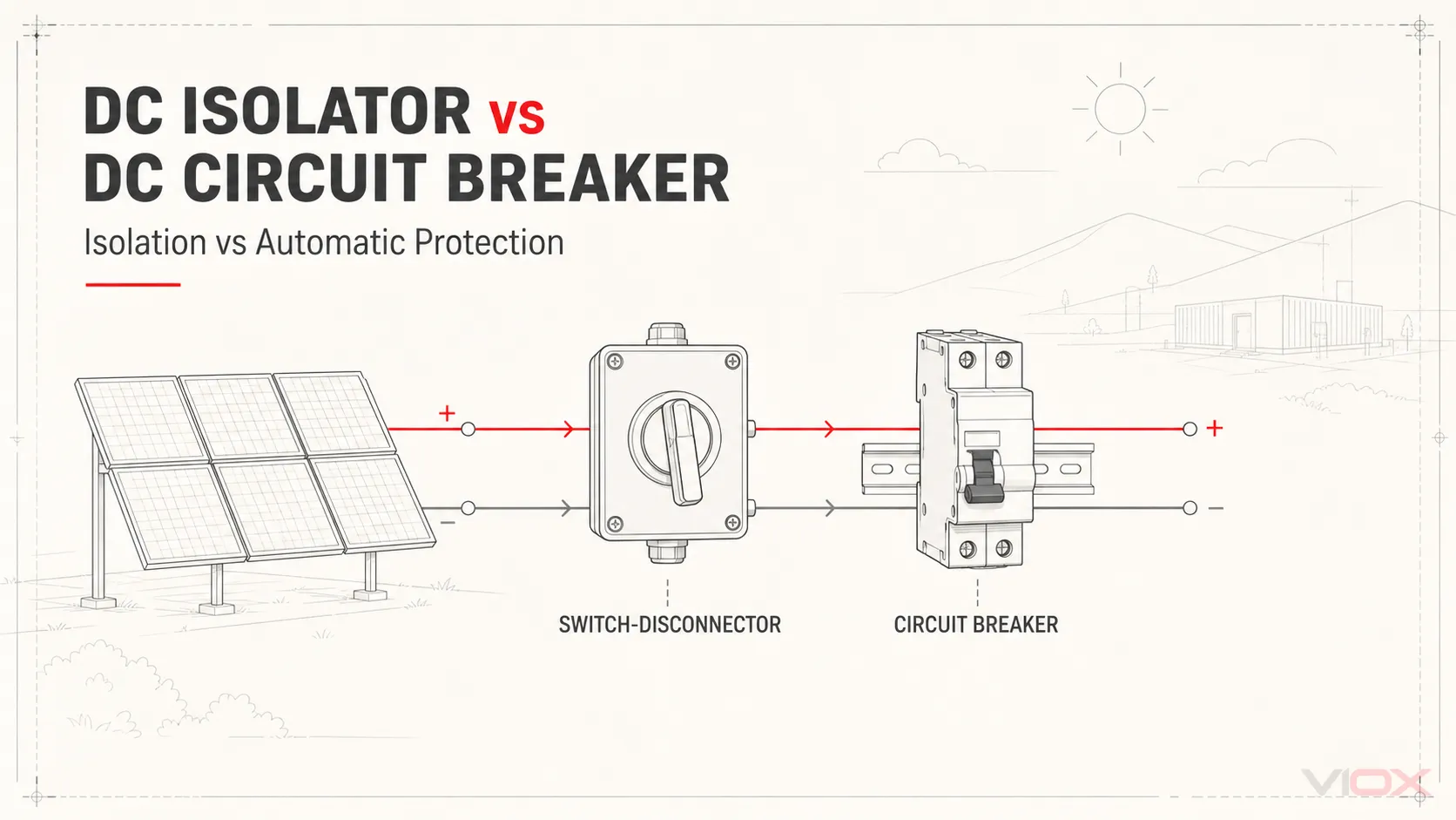
A DC disconnector provides isolation but may not be rated to interrupt load current. A DC switch-disconnector provides isolation and its declared load-switching duty. A DC circuit breaker automatically clears specified overcurrent conditions within its trip characteristics and rated DC breaking capacity.
These devices are not direct substitutes. Many photovoltaic (PV) systems need both isolation and overcurrent-protection functions, although an approved design may not always require two separate devices. A circuit breaker can serve as a disconnecting means only when its rating, marking, locking arrangement, and installation permit that use. A disconnector or switch-disconnector does not provide automatic overcurrent protection.
DC Isolator vs DC Circuit Breaker: Quick Comparison
| Comparison point | DC disconnector or switch-disconnector | DC circuit breaker |
|---|---|---|
| Primary purpose | Intentional circuit isolation | Automatic overcurrent and short-circuit protection |
| Normal operation | Operated manually; load switching only within its declared duty | Trips automatically within its trip characteristics and can also be operated manually |
| Overcurrent protection | No | Yes |
| Short-circuit behavior | No automatic interruption; verify rated short-time withstand current, rated conditional short-circuit current, and coordination with the specified short-circuit protective device (SCPD) | Automatic interruption within its trip characteristics and rated DC breaking capacity |
| Maintenance role | Provides a defined open position and may support lockout | May provide isolation only if approved for that duty |
| Typical PV location | Array, combiner output, inverter input, or other required disconnect point | String, group, feeder, battery, or output protection point |
| Key selection data | DC voltage, current, pole arrangement, utilization category, isolation indication, locking provisions, short-circuit withstand and conditional ratings | DC voltage, current, trip characteristics, breaking capacity, pole arrangement, coordination |
| Relevant IEC product family | IEC 60947-3 for switches, disconnectors, switch-disconnectors, and fuse-combination units | IEC 60947-2 for circuit breakers in industrial applications |
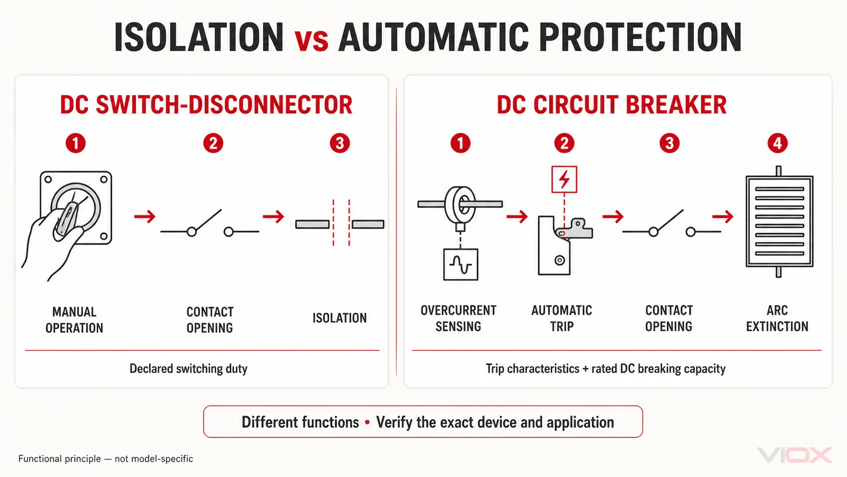
The term DC isolator is often used commercially for a load-break switch-disconnector. That distinction matters. A disconnector intended only for isolation may not be suitable for opening a loaded circuit, while a correctly rated switch-disconnector is designed for its declared switching duty. Always verify the product designation and datasheet rather than relying on the handle label alone.
Why PV Systems Often Need Both Functions
PV modules continue producing DC voltage whenever sufficient light is available. A complete protection strategy therefore has to answer two different questions:
- What automatically interrupts a damaging overcurrent or short circuit?
- What provides deliberate disconnection for inspection, maintenance, or emergency procedures?
The circuit breaker answers the first question. The isolator or approved disconnecting means answers the second.
Automatic Fault Protection
When multiple PV strings are connected in parallel, healthy strings can feed reverse current into a faulted string. Overcurrent protection may therefore be required to protect conductors and equipment, depending on the number of strings, module maximum series-fuse rating, conductor ampacity, and governing design rules.
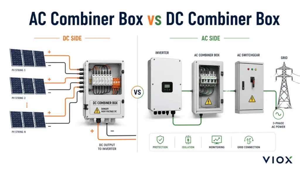
That function can be provided by correctly selected DC circuit breakers, PV fuses, or another accepted protective arrangement. The separate VIOX guide to solar combiner box protection design explains this wider coordination problem.
Intentional Isolation
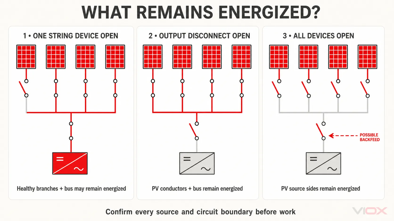
A protective device may trip during a fault, but maintenance personnel still need a clearly defined way to disconnect the intended section of the system. The isolation arrangement must match the actual circuit boundaries: opening a string device does not necessarily isolate the combined bus, and opening an output device does not remove voltage from the PV-side terminals.
This is why device location, labeling, pole configuration, and the shutdown procedure matter as much as the presence of a handle.
Use an energized-zone check before approving the arrangement:
| Switching action | What may be disconnected | What can remain energized |
|---|---|---|
| Open one string breaker or fuse-switch | The protected branch downstream of that device | PV-side terminals of that string and the combined bus from other strings |
| Open the output switch-disconnector | The intended downstream output circuit | The combiner bus and PV-side conductors if strings remain connected |
| Open all string devices and the output disconnect | The internal sections between open devices | Source-side terminals, PV conductors, and any section exposed to battery, inverter, or external backfeed |
The exact energized zones depend on device placement and all possible sources. Confirm them on the single-line diagram and the equipment wiring diagram rather than assuming that one open handle de-energizes the entire enclosure.
Can a DC Breaker Replace a DC Isolator?
Sometimes, but never by assumption. A DC circuit breaker may also serve as a disconnecting means when the applicable code, listing or certification, product marking, installation method, and lockout requirements allow it.
Before using one device for both functions, verify:
- suitability for the maximum PV DC voltage, including cold-corrected open-circuit voltage;
- rated DC breaking capacity at the actual system voltage and pole configuration;
- a clearly indicated open position;
- isolation suitability and any required lock-off provision;
- switching and utilization duty for the intended operating procedure;
- acceptance under the project’s governing code and equipment instructions.
If any of these points is unclear, use separately specified protection and isolation functions.
Can a DC Isolator Replace a DC Circuit Breaker?
No, not where automatic overcurrent protection is required. An isolator does not sense overload or short-circuit current and does not trip automatically. It also cannot selectively clear one faulted string while leaving healthy circuits available.
The isolator may interrupt normal load current if it is specifically rated as a switch-disconnector, but that capability does not turn it into an overcurrent protective device.
Example: A 12-String PV Combiner Box
Consider a combiner box with 12 similar strings connected in parallel. If one string develops a fault, the other 11 strings may contribute reverse current toward it. A simplified screening calculation is:
Potential reverse-current contribution ≈ (number of parallel strings - 1) × string IscFor 12 strings, this gives approximately 11 × Isc before applying the full project calculation and code rules. This approximation assumes similar parallel strings and no additional contribution from a battery, inverter, external supply, or another source. It is only an initial screening value, not a final protective-device rating.
The full assessment must also consider module maximum series-fuse rating, conductor ampacity, prospective short-circuit current, protective-device characteristics, and every possible source of backfeed.
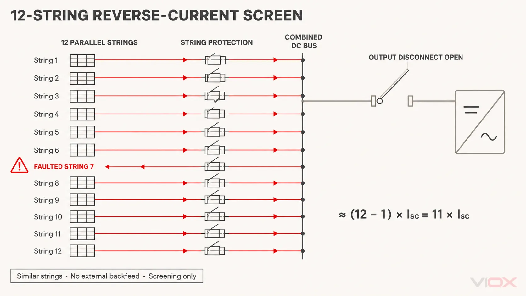
A typical functional arrangement may include:
- string fuses or DC breakers for required branch overcurrent protection;
- a combined DC bus;
- surge protection where specified;
- an output switch-disconnector or another approved disconnecting means.
The layout does not prove compliance on its own. Device ratings, conductor protection, temperature effects, fault current, coordination, and the governing standard still have to be verified.
Device Specification Verification Checklist
Use this as a recordable equipment check, not just a reading list.
| Item to verify | Record from project and device documents | Pass condition |
|---|---|---|
| Required function | Protection, isolation, load switching, or an approved combination | Every required function is assigned to a suitable device |
| Maximum corrected DC voltage | Maximum PV open-circuit voltage at the minimum design temperature | Device DC voltage rating covers the calculated maximum in the stated pole configuration |
| Continuous operating current | Design current, correction factors, ambient temperature, and enclosure grouping | Selected device remains within its declared current capability under installation conditions |
| Breaker fault duty | Prospective DC short-circuit current, trip characteristics, and rated breaking capacity | Breaker can interrupt the calculated duty at the actual voltage and pole arrangement |
| Disconnector withstand duty | Rated short-time withstand current and duration | Declared withstand duty covers the specified fault-clearing interval |
| Conditional short-circuit rating | Declared conditional current and the exact associated SCPD | The installed SCPD, rating, and settings match the manufacturer’s declared combination |
| Switching duty | Device type and utilization category | Intended load switching is within the declared DC duty |
| Isolation and lockout | Open-position indication, isolation suitability, and locking method | Project isolation procedure and local requirements are satisfied |
| Circuit boundary | Single-line diagram and energized-zone review | The device protects or disconnects the intended section with all sources considered |
| Evidence | Datasheet, certificate, manual, and project standard | Model number, ratings, standard scope, and installation instructions agree |
For breaker-specific selection, see the practical guide to DC circuit breakers and the DC circuit breaker sizing guide. For device construction and application, see what a DC isolator switch is.
Standards and Code Boundaries
The governing requirement depends on the market and system type. The following references describe different parts of the decision and should not be treated as interchangeable product certifications.
| Reference | Practical role in this decision |
|---|---|
| IEC 60947-2:2024 | Product requirements for industrial circuit breakers, including devices rated up to 1,500 V DC within its scope |
| IEC 60947-3:2020+A1:2025 | Product requirements for switches, disconnectors, switch-disconnectors, and fuse-combination units |
| IEC 62548-1:2023+A1:2025 | PV array design requirements covering DC wiring, protection devices, switching, and earthing provisions |
| IEC 60364-7-712:2025 | Selection and application requirements for equipment in PV electrical installations, including current PV system architectures |
| NFPA 70 (NEC), Article 690 | U.S. PV requirements; use the edition adopted by the authority having jurisdiction (AHJ) |
| Local installation rules | May add placement, labeling, accessibility, enclosure, or emergency-isolation requirements |
Do not describe a product as compliant with any standard unless the exact model’s certificate, marking, and scope support that claim.
Common Selection Mistakes
Using an AC-Only Device in a DC Circuit
DC interruption is more demanding because the arc has no natural current zero crossing. Use a device with an explicit DC rating for the actual voltage, current, pole arrangement, and switching or breaking duty.
Choosing by Current Rating Alone
An ampere rating does not establish DC voltage suitability, breaking capacity, utilization category, or isolation performance. All relevant ratings must match the application.
Assuming Every Breaker Is an Isolator
A breaker handle does not automatically prove that the device provides the required isolation, visible indication, or lockout arrangement.
Treating the Output Isolator as String Protection
An output disconnect cannot automatically provide selective overcurrent protection for individual strings. Evaluate reverse-current exposure and branch protection separately.
Installing the Disconnect at the Wrong Circuit Boundary
The selected device must disconnect the section technicians expect it to isolate. Draw the energized zones for every switching state before finalizing the layout.
Frequently Asked Questions
Do all PV systems need a separate DC isolator and DC circuit breaker?
No. Many systems need both isolation and overcurrent-protection functions, but those functions do not always require two separate devices. The correct arrangement depends on circuit exposure, equipment ratings, applicable rules, and whether a breaker is approved as a disconnecting means.
Can a DC circuit breaker be used as an on-off switch?
Only when the manufacturer permits the intended switching frequency and duty. A breaker that can be manually operated is not automatically suitable for routine switching.
Does a DC isolator trip during a short circuit?
No. A standard DC isolator does not detect fault current or trip automatically. Short-circuit protection must come from a correctly rated circuit breaker, fuse, or other accepted protective device.
Where are the devices installed in a combiner box?
Overcurrent devices are commonly installed at string, string-group, or output level according to the protection design. A switch-disconnector is often placed at the combined output when local whole-box disconnection is required. The exact arrangement depends on the circuit boundaries and governing rules.
Which device is safer?
Neither is universally safer because they address different hazards. A circuit breaker protects against defined overcurrent conditions; an isolator or switch-disconnector supports intentional disconnection. Safety depends on selecting and coordinating the required functions correctly.
Conclusion
The practical difference is simple: a DC circuit breaker clears specified overcurrent conditions within its trip characteristics and rated DC breaking capacity. A disconnector provides isolation, while a switch-disconnector adds its declared load-switching duty. A suitably approved breaker may sometimes perform both protection and isolation roles, but a disconnector cannot replace required overcurrent protection.
Define the protection function, isolation boundary, maximum corrected voltage, current, fault duty, and applicable standard before selecting either device. Then verify the exact model against its datasheet, declared short-circuit ratings, associated SCPD requirements, and the project diagrams.