
Direct Answer: Circuit breaker mechanical properties are measured using specialized circuit breaker analyzers equipped with motion transducers that capture real-time contact movement during operation. The three critical parameters—contact speed (typically 0.5-10 m/s), rebound (should be <5% of stroke), and overtravel (should be <5% of stroke)—are analyzed from travel curves generated during open and close operations. Modern testing equipment simultaneously records timing, motion, and electrical parameters to provide comprehensive diagnostic data that reveals mechanical wear, damping issues, and potential failures before they cause system downtime.
Key Takeaways
- Understanding circuit breaker mechanical testing is essential for maintaining reliable electrical protection systems.
- Contact speed measurement verifies the breaker can interrupt fault currents within the arcing zone, typically requiring velocities between 0.5-10 m/s depending on breaker type and voltage class.
- Excessive rebound indicates damping system failure, which can lead to contact welding and reduced electrical life.
- Overtravel beyond manufacturer specifications signals mechanical stress that accelerates wear on operating mechanisms.
- According to CIGRE working group A3.06 research, 50% of major circuit breaker failures originate from operating mechanism defects, making mechanical property testing a critical predictive maintenance tool.
- Professional testing requires circuit breaker analyzers compliant with IEC 60947-2 and IEEE C37.09 standards, motion transducers with appropriate stroke length, and baseline reference data from commissioning tests for meaningful trend analysis.
Why Circuit Breaker Mechanical Testing Matters
Circuit breakers represent the first line of defense in electrical distribution systems, yet their mechanical performance often receives less attention than electrical characteristics. The mechanical operating mechanism must function flawlessly within milliseconds to protect equipment and personnel from fault conditions.
Research from the Electric Power Research Institute (EPRI) demonstrates that mechanical failures account for the majority of circuit breaker malfunctions. When a breaker fails to operate at the correct speed, exhibits excessive rebound, or shows abnormal overtravel, the consequences extend beyond the device itself—potentially compromising the entire electrical system’s protection coordination.
Traditional timing-only tests provide limited insight into breaker health. A breaker may pass timing specifications while harboring mechanical defects that manifest as improper contact velocity, insufficient damping, or excessive mechanical stress. Comprehensive mechanical property analysis reveals these hidden problems before they escalate into catastrophic failures.
Understanding the Three Critical Mechanical Parameters
Contact Speed: The Velocity Factor
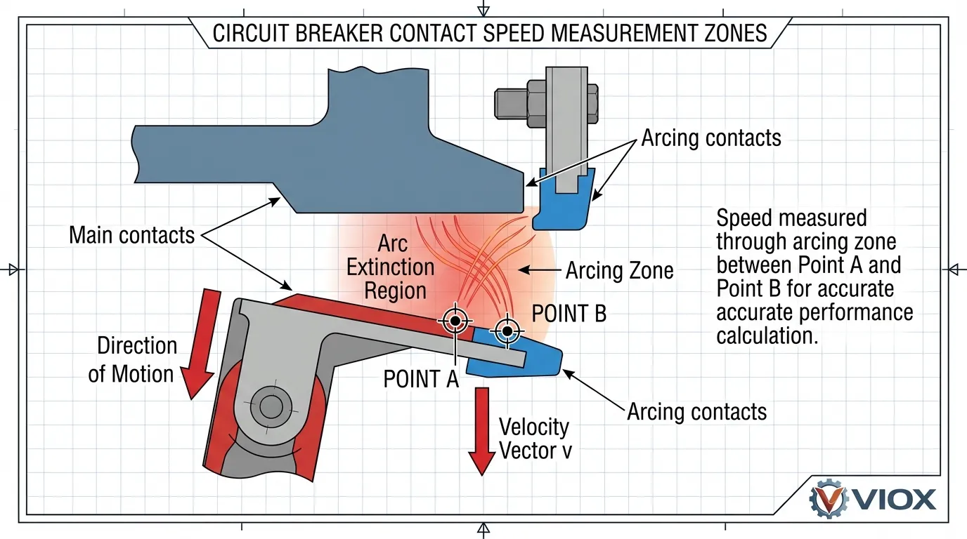
Contact speed represents the velocity at which breaker contacts move through the arcing zone during opening operations. This parameter directly affects the breaker’s ability to extinguish electrical arcs and interrupt fault currents safely.
Proper contact speed ensures the arc is stretched and cooled sufficiently for reliable interruption. Too slow, and the arc may not extinguish, leading to failure to interrupt. Too fast, and excessive mechanical stress damages the operating mechanism and contacts. Manufacturers specify acceptable speed ranges based on breaker design, interrupting medium, and voltage class.
Speed is calculated between two defined points on the motion curve, typically within the arcing zone where contact separation occurs. Modern circuit breaker analyzers compute both average and instantaneous velocity, providing detailed insight into mechanism performance throughout the operating cycle.
Rebound: The Damping Indicator
Rebound occurs when contacts travel past their final resting position after completing an operation, then bounce back toward the opposite position. This oscillatory motion indicates the effectiveness of mechanical damping systems within the breaker.
Excessive rebound signals damping system degradation—often caused by worn dashpots, depleted hydraulic fluid, or mechanical linkage problems. Unchecked rebound can lead to contact damage, reduced electrical endurance, and eventual mechanical failure. Industry standards typically limit rebound to less than 5% of total stroke length.
Rebound measurement requires precise motion tracking throughout the entire operating cycle. The parameter is calculated as the distance from minimum displacement (after maximum overtravel) to the final resting position of the contacts.
Overtravel: The Mechanical Stress Indicator
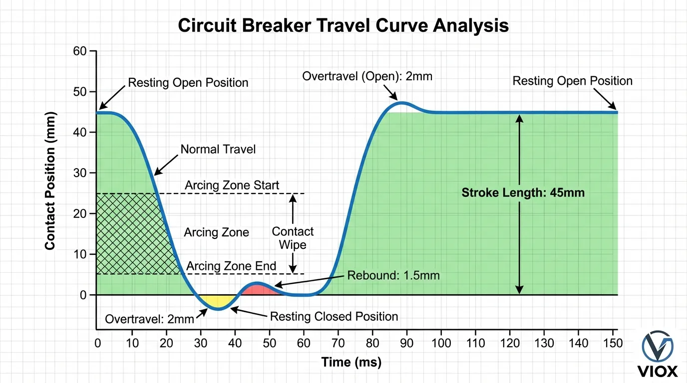
Overtravel represents the distance contacts move beyond their intended final position during close or open operations. This parameter reveals mechanical energy absorption and stress levels within the breaker mechanism.
Controlled overtravel is designed into circuit breakers to ensure positive contact pressure and reliable latching. However, excessive overtravel indicates problems with mechanical stops, energy absorption systems, or operating mechanism calibration. Like rebound, overtravel should typically remain below 5% of total stroke.
Overtravel is measured directly from the travel curve as the maximum displacement beyond the resting position during the operation. Both closing and opening operations exhibit overtravel characteristics that must be evaluated independently.
Essential Testing Equipment and Setup
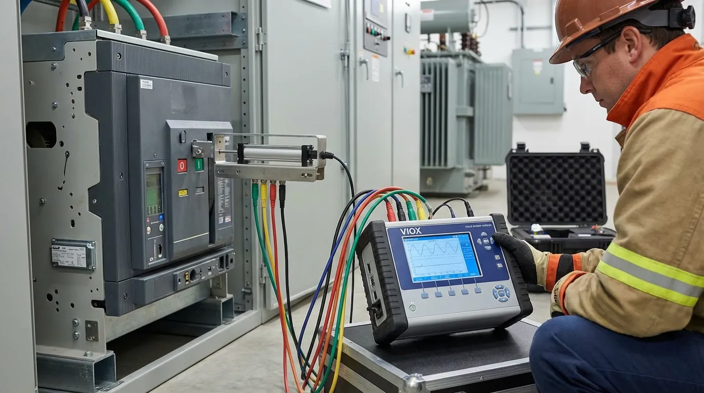
Circuit Breaker Analyzers
Modern circuit breaker testing requires sophisticated analyzers capable of simultaneously measuring multiple parameters. Professional-grade instruments provide:
- Timing channels that record main contact operations, pre-insertion resistor timing (if present), auxiliary contact sequences, and pole synchronization. These channels typically offer microsecond resolution to capture fast-acting breaker operations accurately.
- Motion transducer inputs that accept analog or digital signals from displacement sensors. Universal transducer channels accommodate various sensor types, allowing flexibility in mounting arrangements and measurement configurations.
- Coil current monitoring that tracks operating coil behavior during trip and close operations. Current signature analysis reveals electrical and mechanical problems in actuating coils before they cause operational failures.
- Data analysis software that automatically calculates derived parameters, compares results to manufacturer specifications, generates trend reports, and stores historical data for condition-based maintenance programs.
Motion Transducers and Mounting
Motion measurement accuracy depends entirely on proper transducer selection and installation. Linear transducers are most common, providing voltage output proportional to displacement. Rotary transducers measure angular motion, which the analyzer converts to linear displacement using manufacturer-supplied conversion factors.
Critical mounting considerations include transducer stroke length sufficient to capture total travel plus overtravel, secure mounting that prevents transducer movement during operation, alignment that ensures measurement accuracy throughout the stroke, and safety clearances that protect equipment from moving breaker components.
The transducer must attach to a moving part of the breaker mechanism that accurately represents main contact motion. Common attachment points include the operating rod, mechanism linkage, or interrupter assembly, depending on breaker design and accessibility.
Step-by-Step Testing Procedure
Pre-Test Preparation and Safety
Before beginning mechanical property testing, ensure the circuit breaker is properly isolated from all power sources. Verify that stored energy systems (springs, hydraulic accumulators, pneumatic systems) are safely discharged or controlled. Confirm that all personnel are clear of moving parts and that appropriate lockout/tagout procedures are in place.
Review manufacturer documentation to identify recommended test procedures, acceptable parameter ranges, and specific precautions for the breaker model being tested. Gather baseline data from previous tests or commissioning records to enable meaningful comparison and trend analysis.
Equipment Connection and Configuration
Connect the circuit breaker analyzer timing channels to appropriate test points on the breaker. For three-phase breakers, this typically involves connections to all three poles to measure synchronization and individual pole performance. Attach auxiliary contact monitoring leads if auxiliary timing is required.
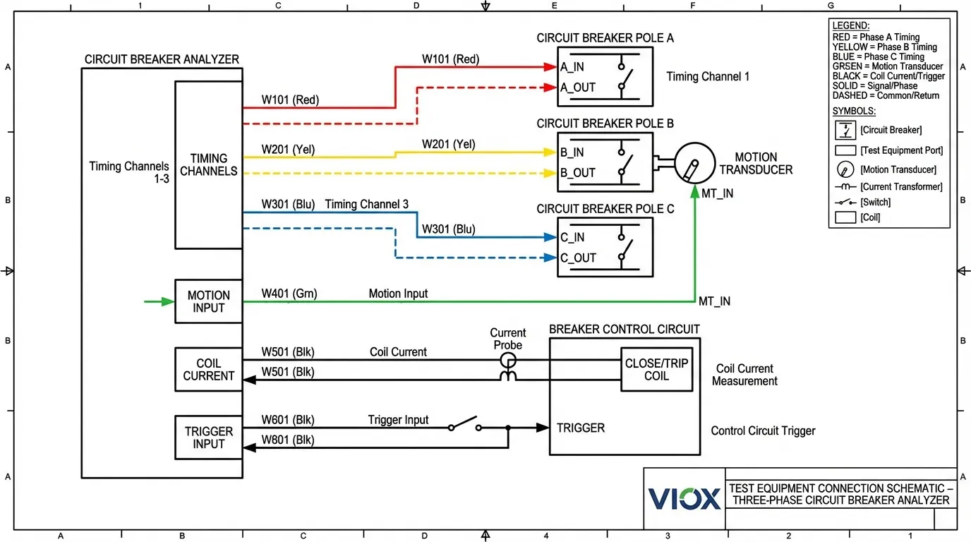
Install the motion transducer according to manufacturer instructions, ensuring proper alignment and secure mounting. Connect the transducer output to the analyzer’s motion input channel. Configure the analyzer with appropriate transducer calibration data, including stroke length, conversion factors, and measurement units.
Set up the analyzer to trigger on the appropriate control signal—either the breaker’s own control circuit or an external trigger from the test equipment. Configure measurement parameters including sample rate, recording duration, and calculation points for speed determination.
Executing the Test Sequence
Initiate a close operation and allow the analyzer to capture the complete motion profile. Review the resulting travel curve for proper shape, absence of anomalies, and reasonable parameter values. Repeat the close operation at least three times to verify consistency and identify any intermittent problems.
After completing close operations, perform open operation tests following the same procedure. Capture multiple operations to establish reliable baseline data and verify repeatability. For comprehensive assessment, test the breaker under both normal and minimum operating voltage conditions to evaluate performance across the operating range.
Record all test data systematically, including environmental conditions (temperature, humidity), breaker status (number of operations, maintenance history), and any observed anomalies during testing. This documentation proves essential for trend analysis and future troubleshooting.
Data Analysis and Interpretation
Analyze the travel curves to extract key parameters. Measure stroke length from the resting open position to the resting closed position. Identify overtravel as the maximum displacement beyond the resting position. Calculate rebound as the distance from minimum displacement back to final rest.
Determine contact speed by identifying the arcing zone boundaries (typically specified by the manufacturer) and calculating velocity between these points. Compare all measured values to manufacturer specifications and previous test results. Deviations exceeding 10-15% from baseline values warrant investigation and potential corrective action.
Interpreting Test Results: What the Numbers Reveal
Normal Operating Ranges
Acceptable mechanical property values vary significantly by breaker type, voltage class, and manufacturer design. However, general guidelines provide useful reference points for evaluation.
- Contact speed typically ranges from 0.5 m/s for low-voltage molded case circuit breakers to 10 m/s for high-voltage power circuit breakers. The specific acceptable range depends on interrupting medium (air, vacuum, SF6) and arc extinction requirements. Speeds within ±20% of manufacturer specifications generally indicate satisfactory performance.
- Rebound and overtravel should both remain below 5% of total stroke length for most circuit breaker designs. Values approaching or exceeding this threshold suggest damping system degradation requiring investigation and potential maintenance intervention.
- Stroke length should match manufacturer specifications within ±5%. Significant deviations indicate mechanical wear, adjustment problems, or linkage issues requiring correction.
Warning Signs and Failure Indicators
Certain test results provide clear warning of impending problems. Contact speed reduction of 20% or more from baseline values indicates increased mechanical friction, lubrication degradation, or binding in the operating mechanism. This condition will worsen over time and eventually lead to failure to operate.
Rebound exceeding 10% of stroke length signals severe damping system failure. This condition accelerates contact wear and can lead to contact welding, reduced interrupting capacity, and mechanical damage to the operating mechanism. Immediate corrective action is required.
Increasing overtravel trends indicate energy absorption system degradation or mechanical stop wear. While not immediately critical, this condition should be monitored closely and addressed during the next scheduled maintenance outage.
Asymmetry between poles in three-phase breakers reveals synchronization problems that can affect protection coordination and system reliability. Pole-to-pole timing differences exceeding IEC 60947-2 limits (3.33 ms at 50 Hz, 2.78 ms at 60 Hz for opening) require mechanism adjustment or repair.
Comparison of Testing Methods and Standards
| Testing Method | Measurement Capability | Applicable Standards | Typical Applications | Equipment Complexity | Cost Range |
|---|---|---|---|---|---|
| Contact Timing Only | Operating times, pole synchronization | IEC 60947-2, IEEE C37.09 | Basic maintenance verification | Low | $2,000-$5,000 |
| Timing + Motion Analysis | All mechanical parameters, complete diagnostics | IEC 60947-2, IEEE C37.09, NETA standards | Comprehensive condition assessment | Medium | $8,000-$15,000 |
| Dynamic Resistance + Motion | Contact wear analysis, arcing contact condition | IEC 62271-100, manufacturer specifications | Advanced diagnostics, life assessment | High | $15,000-$30,000 |
| Vibration Analysis | Non-invasive mechanism assessment | Manufacturer-specific | In-service monitoring, first-trip testing | Medium | $10,000-$20,000 |
| Coil Current Analysis | Electrical/mechanical interaction, energy delivery | IEC 60947-2, IEEE C37.09 | Control circuit diagnostics | Low-Medium | $5,000-$12,000 |
Mechanical Property Specifications by Breaker Type
| Breaker Type | Typical Stroke Length | Acceptable Speed Range | Rebound Limit | Overtravel Limit | Testing Frequency |
|---|---|---|---|---|---|
| Miniature Circuit Breaker (MCB) | 3-8 mm | 0.5-2 m/s | <5% of stroke | <5% of stroke | Not typically tested (sealed units) |
| Molded Case Circuit Breaker (MCCB) | 8-15 mm | 1-3 m/s | <5% of stroke | <5% of stroke | Every 5 years or after fault operation |
| Low-Voltage Power Circuit Breaker | 15-50 mm | 2-5 m/s | <5% of stroke | <5% of stroke | Every 2-3 years or after fault operation |
| Medium-Voltage Vacuum Circuit Breaker | 10-20 mm | 0.8-1.5 m/s | <3% of stroke | <3% of stroke | Annually or after fault operation |
| High-Voltage SF6 Circuit Breaker | 100-300 mm | 3-10 m/s | <5% of stroke | <5% of stroke | Annually or after fault operation |
Advanced Diagnostic Techniques
Dynamic Resistance Measurement
Dynamic resistance measurement (DRM) represents an advanced diagnostic technique that combines motion analysis with high-current resistance testing. By injecting test current through the breaker contacts while simultaneously measuring voltage drop and contact motion, DRM reveals contact condition and wear that cannot be detected through motion analysis alone.
The technique identifies arcing contact wear by analyzing the resistance profile during contact separation. As contacts open, the resistance curve shows distinct transitions as main contacts separate (resistance increases), arcing contacts carry current (relatively stable resistance), and finally arcing contacts separate (resistance rises sharply). The length of the arcing contact engagement can be calculated from the motion and resistance curves, providing direct measurement of contact wear.
DRM testing requires specialized equipment capable of injecting 100-600 amperes DC current while simultaneously recording voltage drop with microohm resolution and tracking contact motion. The test must be performed with proper safety precautions, as it involves high current injection into isolated breaker contacts.
Vibration Analysis for Non-Invasive Assessment
Vibration analysis offers a non-invasive alternative to traditional motion measurement, particularly valuable for in-service testing and first-trip assessment. An accelerometer attached to the breaker housing captures vibration signatures during operation, which are analyzed to assess mechanical condition without requiring transducer attachment to moving parts.
The vibration signature contains information about mechanism operation, contact impact, damping effectiveness, and mechanical anomalies. By comparing current vibration patterns to baseline signatures, technicians can detect changes indicating wear, misalignment, or developing problems. Vibration analysis proves especially effective for detecting first-trip problems caused by corrosion or lubrication degradation after extended idle periods.
While vibration analysis provides valuable diagnostic information, it should be considered complementary to rather than a replacement for direct motion measurement. The technique excels at detecting changes and anomalies but provides less precise quantification of specific mechanical parameters compared to transducer-based motion analysis.
Establishing a Condition-Based Maintenance Program
Effective circuit breaker maintenance programs leverage mechanical property testing to transition from time-based to condition-based strategies. This approach optimizes maintenance resources while improving reliability through targeted intervention based on actual equipment condition.
The foundation of condition-based maintenance is establishing baseline data during commissioning or initial testing. These reference measurements provide the comparison standard for all future tests. Baseline data should include multiple operations under various conditions to capture normal performance variation.
Periodic testing intervals depend on breaker type, application criticality, and operating environment. Critical breakers in harsh environments may require annual testing, while less critical devices in controlled environments may be tested every 3-5 years. Fault operations should always trigger testing to verify continued proper operation and detect any damage requiring correction.
Trend analysis reveals gradual degradation before it reaches critical levels. Plotting key parameters over time identifies developing problems and enables proactive maintenance scheduling. Parameters showing consistent degradation trends warrant increased monitoring frequency and maintenance planning, even if current values remain within acceptable limits.
Common Problems Revealed by Mechanical Testing
Damping System Failures
Damping system degradation represents one of the most common problems revealed by mechanical property testing. Hydraulic dashpots lose fluid through seal leakage, pneumatic dampers develop valve problems, and mechanical friction dampers wear over time. These failures manifest as increased rebound and overtravel, along with changes in contact speed profiles.
Early detection through testing enables planned maintenance intervention before the problem causes operational failure or contact damage. Damping system repair typically involves fluid replacement, seal renewal, or adjustment of damping components—relatively straightforward maintenance tasks when performed proactively.
Lubrication Degradation
Inadequate or degraded lubrication increases mechanical friction throughout the operating mechanism. This condition manifests as reduced contact speed, increased operating time, and irregular motion profiles. First-trip testing after extended idle periods proves particularly effective at detecting lubrication problems before they cause failure during critical fault clearing operations.
Lubrication maintenance should follow manufacturer recommendations regarding lubricant type, application points, and service intervals. Over-lubrication can be as problematic as under-lubrication, potentially attracting contaminants or interfering with proper mechanism operation.
Mechanical Wear and Misalignment
Long-term operation causes wear at pivot points, linkage connections, and bearing surfaces throughout the breaker mechanism. This wear manifests as increased play in the mechanism, changes in stroke length, and pole-to-pole synchronization problems in three-phase breakers.
Motion analysis reveals these problems through changes in travel curve shape, increased variation between operations, and deviations from baseline measurements. Addressing mechanical wear may require adjustment, component replacement, or complete mechanism overhaul depending on severity and breaker design.
Integration with Other Diagnostic Tests
Mechanical property testing provides maximum value when integrated with other circuit breaker diagnostic techniques. Contact resistance testing verifies electrical connection quality and detects contact erosion or contamination. Insulation resistance testing assesses dielectric integrity of insulating components. Coil current analysis evaluates control circuit performance and energy delivery to the operating mechanism.
The combination of these tests provides comprehensive circuit breaker condition assessment. For example, increased contact resistance combined with reduced stroke length suggests contact wear requiring maintenance. Normal contact resistance with reduced speed indicates mechanical friction problems rather than contact issues. This integrated diagnostic approach enables accurate problem identification and targeted corrective action.
Related Topics
- For readers seeking deeper understanding of circuit breaker fundamentals, our guide on types of circuit breakers provides comprehensive coverage of different breaker designs and their applications.
- Understanding circuit breaker ratings helps interpret test results in the context of breaker specifications and protection requirements.
- The relationship between mechanical and electrical performance is explored in our article on understanding trip curves, which explains how mechanical operating characteristics affect protection coordination.
- For industrial applications, our guide on how to select an MCCB for a panel addresses selection criteria including mechanical performance requirements.
- Maintenance professionals will find valuable information in our article on how to really test MCCB, which explains why mechanical testing provides more reliable assessment than simple test button operation.
- Understanding what causes circuit breaker failures helps contextualize the importance of proactive mechanical testing in preventing unexpected failures.
Frequently Asked Questions
How often should circuit breaker mechanical properties be tested?
Testing frequency depends on breaker type, application criticality, and operating environment. Critical breakers protecting essential equipment should be tested annually, while less critical devices may be tested every 3-5 years. Always test after fault clearing operations or when visual inspection reveals potential problems. Establishing a baseline during commissioning enables effective trend analysis during subsequent periodic testing.
Can mechanical testing damage the circuit breaker?
When performed correctly using appropriate equipment and procedures, mechanical testing does not damage circuit breakers. The test simply operates the breaker through normal open-close cycles while measuring performance parameters. However, improper transducer mounting, excessive test repetitions, or testing with improper operating voltage can potentially cause problems. Always follow manufacturer recommendations and use qualified personnel for testing.
What is the difference between timing testing and motion analysis?
Contact timing testing measures only the time intervals for contact operations—when contacts close, open, and the synchronization between poles. Motion analysis extends this by measuring the actual physical movement of contacts throughout the operating cycle, revealing stroke length, speed, overtravel, and rebound. Motion analysis provides much more comprehensive diagnostic information about mechanical condition than timing alone.
Why do some manufacturers not recommend mechanical testing?
Some manufacturers, particularly of sealed low-voltage devices like miniature circuit breakers, do not recommend field testing because these devices are designed as non-serviceable units. Testing would require disassembly that compromises the sealed construction. However, most industrial and power circuit breakers are designed for periodic testing and maintenance, with manufacturers providing detailed test procedures and acceptance criteria.
How do you establish baseline values if no commissioning data exists?
When baseline data is unavailable, test multiple similar breakers of the same model if possible to establish typical performance characteristics. Compare results to manufacturer specifications when available. Alternatively, establish current measurements as the baseline and monitor for changes during future testing. Even without historical data, mechanical testing reveals gross abnormalities and enables trend analysis going forward.
What qualifications are needed to perform circuit breaker mechanical testing?
Mechanical testing should be performed by qualified electrical technicians or engineers with training in circuit breaker operation, electrical safety, and test equipment operation. Many organizations require NETA certification or equivalent qualifications for personnel performing circuit breaker testing. Proper training in equipment operation, safety procedures, and result interpretation is essential for effective testing and personnel safety.
VIOX Electric manufactures high-quality circuit breakers and electrical protection equipment designed for reliable performance and easy maintenance. Our products incorporate features that facilitate mechanical property testing and condition assessment, supporting effective preventive maintenance programs. Contact our technical team for assistance with circuit breaker selection, testing procedures, or maintenance planning for your specific application requirements.
