এই পৃষ্ঠায়
Choose a campervan consumer unit against every AC supply mode the vehicle will use, not just the number of sockets. The board must provide the specified isolation, circuit protection and distribution when connected to shore power, running from an inverter, or passing shore power through an inverter/charger. A board that works on a campsite hook-up is not automatically suitable when the inverter becomes the source.
This guide helps conversion designers and buyers specify a 230 V habitation AC board in a UK/IEC context. It is not a terminal-wiring guide, a battery-system design or a North American RV-panel specification.
By VIOX Team. Sources checked: October 9, 2026.
Start With the Supply Modes, Then Choose the Board
Record which source can energize each circuit before selecting the enclosure or protective devices.
| Vehicle arrangement | What the consumer-unit specification must resolve | অনুমোদনের আগে প্রমাণ প্রয়োজন |
|---|---|---|
| Shore power only | Inlet protection, main isolation and final-circuit protection | Supply arrangement, circuit design and applicable caravan installation requirements |
| Inverter only | Protection effective on the exact inverter output | Permitted fixed-wiring use, fault behavior, earthing arrangement and compatible protective devices |
| Shore power plus a separate inverter | Controlled source selection without unintended backfeed | Approved changeover arrangement, conductor switching and mode-specific protection |
| Inverter/charger with AC pass-through | Both pass-through and battery-inverting operation | Input/output protection requirements, transfer function and maximum output under each enabled mode |
Key selection checks: distinguish load current from fault current; preserve the required inlet protection; and confirm the neutral, earthing and isolation arrangement separately for each source mode.
Do not connect an inverter output and shore supply together simply because both are nominally 230 V. Where equipment permits an assist or parallel function, it belongs to that equipment’s documented architecture, not an improvised connection at the board.
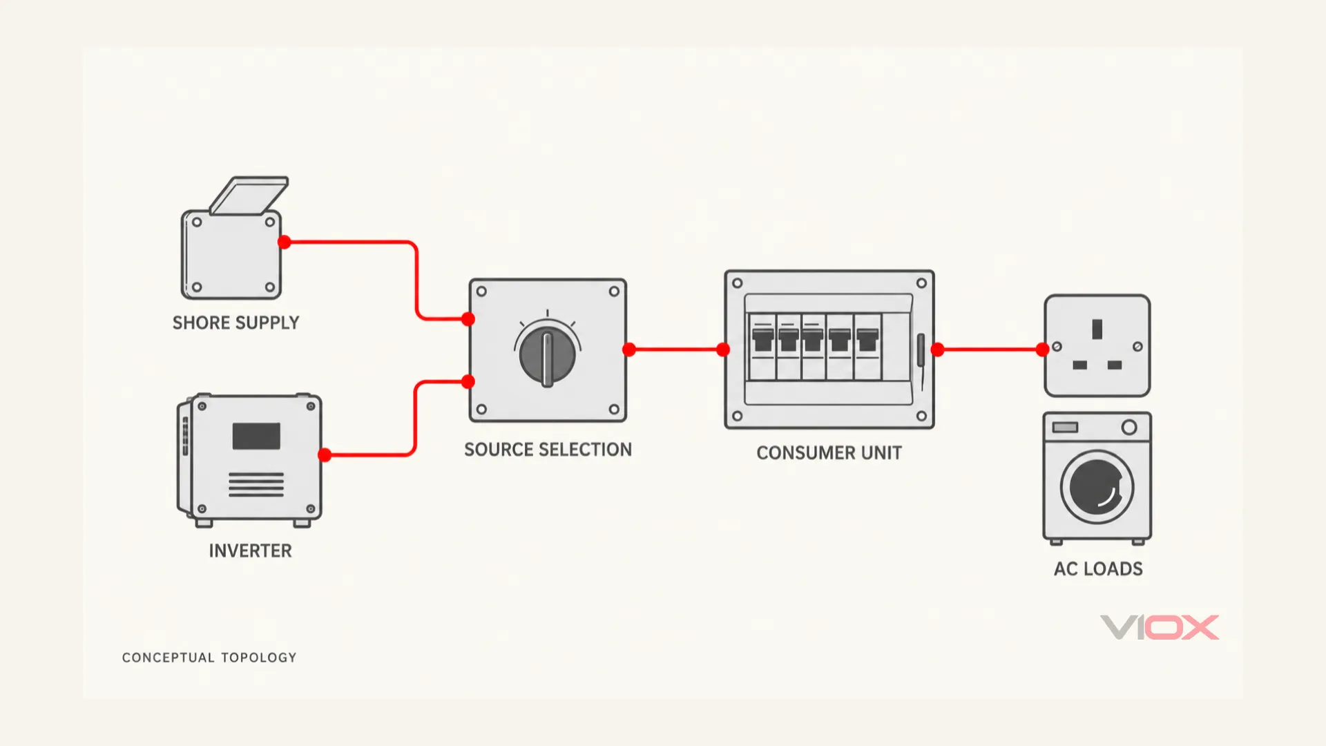
Separate-inverter source-selection concept; an inverter/charger may integrate the transfer function. Inlet protection, inverter input/output protection, conductor switching and bonding must be established in the project design. This is not a terminal-wiring diagram.
Where the Campervan Consumer Unit Fits
The consumer unit is the vehicle’s habitation AC distribution assembly. It does not replace protection for batteries, alternator charging or photovoltaic wiring. For the basic board components, see একটি কনজিউমার ইউনিটে কী থাকে.
IEC 60364-7-721:2017 specifically addresses caravan and motorcaravan habitation circuits and equipment. Its published summary requires an accessible main isolating switch that disconnects all live conductors for each independent installation.
For a UK project, identify the applicable BS 7671 edition and amendments, including Section 721. Use the IET edition checker rather than relying on an undated wiring diagram. The campsite supply and the vehicle installation are separate design boundaries; accepting a hook-up does not establish that everything downstream is correctly protected.
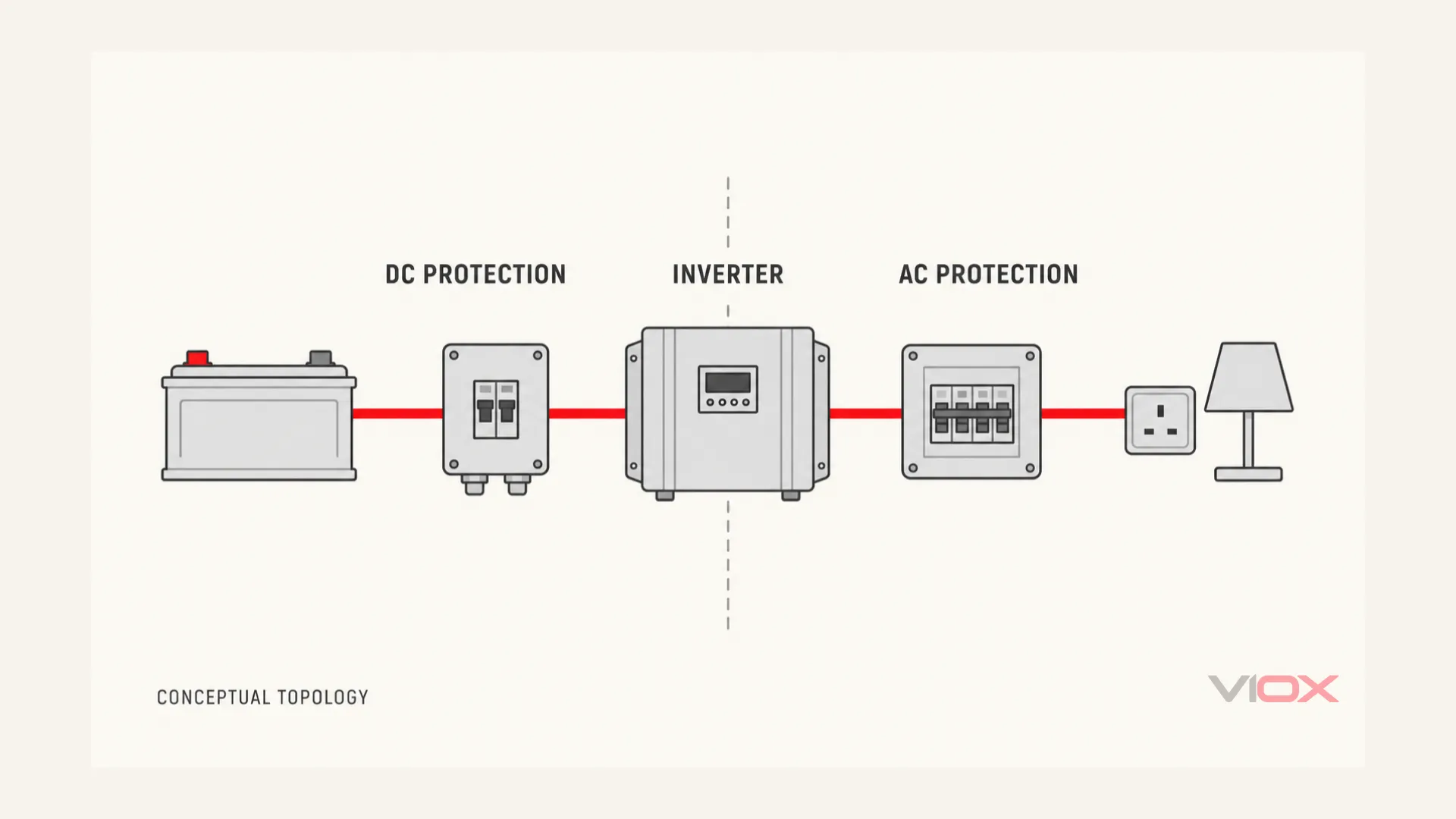
The inverter interfaces two protection domains. An AC consumer unit does not provide the battery or PV circuit’s DC fault protection. The figure omits installation wiring and model-specific protective-device positions.
Specify Isolation, Overcurrent and Residual-Current Protection Separately
These are different functions even when one device combines some of them.
| ফাংশন | Device or arrangement to evaluate | Selection point |
|---|---|---|
| Main isolation | Suitable main isolating device or verified combined arrangement | Required live conductors disconnected; accessible operation; all sources addressed by the isolation plan |
| ওভারলোড এবং শর্ট-সার্কিট সুরক্ষা | Miniature circuit-breaker (MCB), RCBO or other specified overcurrent protective device | Cable protection, trip characteristic, fault-current duty and manufacturer coordination |
| অবশিষ্ট-কারেন্ট সুরক্ষা | Appropriate residual current device (RCD), including an RCCB or RCBO | Operating current, waveform type, switched conductors, position and behavior under each supply mode |
| Source selection | Compatible transfer/changeover arrangement, sometimes integrated into an inverter/charger | Permitted source combinations, switching sequence and backfeed prevention |
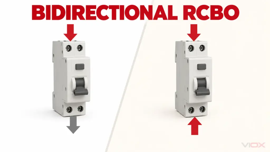
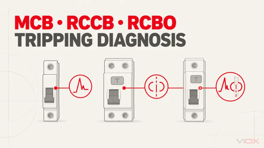
একটি RCCB, a residual current operated circuit-breaker without integral overcurrent protection, needs coordinated overcurrent protection. An আরসিবিও, a residual current operated circuit-breaker with integral overcurrent protection, combines the two functions. These functions are distinguished in আইইসি (IEC) ৬১০০৮-১:২০২৪ এবং আইইসি (IEC) ৬০০৯-১:২০২৪. Neither label, by itself, proves that the device satisfies every isolation or vehicle requirement. Have the designer identify any additional protective functions required by the project rules.
Do Not Remove Inlet Protection Just Because the Board Has RCBOs
The IET’s 2018 explanation of Section 721 describes an associated RCD directly connected to each supply inlet. Where automatic disconnection of supply is the protective measure, it describes residual-current protection not exceeding 30 mA and disconnection of all live conductors. This historical explanation is a useful boundary check, not a substitute for the project edition’s complete requirements.
Individual RCBOs can separate final-circuit protection, but they do not automatically protect the inlet-to-board section or eliminate a required upstream RCD. The designer must resolve protection coverage and coordination before choosing an all-RCBO or shared-RCD arrangement. The broader RCBO consumer-unit selection guide addresses board architecture; the vehicle’s source and inlet conditions still need their own review.
For single-phase equipment, verify exactly what the selected device switches and what it protects. A two-module housing or a marking such as 1P+N does not, on its own, establish the complete pole and isolation requirement for the installation.
Make Each Operating Mode Pass Its Own Protection Review
Use the following matrix as an acceptance record. A blank consequential field means the design is not ready for release, even if the appliances operate normally.
| পরীক্ষা করুন | Shore-connected mode | Inverter mode | Transfer or pass-through mode |
|---|---|---|---|
| Available supply | Declared inlet and upstream supply limits | Continuous output and permitted overload behavior | Pass-through limit and any enabled assist function |
| Fault protection | Fault-current/disconnection assessment for the external supply | Model-specific fault output and protection behavior | Applicable protective path in each state |
| RCD coverage | Inlet and final circuits covered as required | Protected loads remain covered off-grid | No unreviewed bypass during source changes |
| Earthing and neutral | External supply arrangement identified | Output reference and bonding strategy documented | Switching/reference sequence established by the equipment design |
| আলাদা করা | Shore-fed sections and other sources identified | Battery-derived AC cannot defeat the isolation plan | Controls and procedures address both sources |
Inverter Watts Do Not Prove Breaker Operation
An electronic inverter may limit fault current instead of sustaining the high current available from a public supply. Its nominal power therefore cannot establish that a selected MCB will achieve the required fault disconnection. The IET discusses this distinction in its island-mode protection guidance; that article concerns residential prosumer installations, not a ready-made caravan design.
For the exact inverter, request the fault-current/time behavior, shutdown characteristics and permitted downstream protection. A higher breaker rating is not a remedy for missing fault evidence. Changing a trip curve also requires a circuit protection assessment.
Neutral, Earthing and RCD Selection Belong to the System Design
Confirm the output arrangement, any internal reference switching, compatible RCD type and behavior if supply voltage collapses. These depend on the source and connected equipment; a universal Type A or Type B instruction is inappropriate here.
Do not copy a neutral-to-earth link from a generic van drawing. A link appropriate to one operating state may conflict with another. Ask for the exact inverter/charger instructions and the designer’s approved earthing and transfer arrangement. The required evidence is a coordinated design, not a photograph of another conversion.
The IET also explains that a protection study must be reviewed for connected and independent-source operation. Testing only with shore power connected leaves the off-grid operating condition unresolved.
Build a Circuit Schedule Without Guessing Breaker Sizes
List each circuit’s load, cable design and permitted sources. For example, a converter may want selected sockets available off-grid while keeping a large charger or heating load shore-only. That is a circuit-allocation decision, not a reason to connect both sources indiscriminately.
The following is an illustrative schedule, not a recommended fuse or breaker kit:
| সার্কিট | Required source availability | Inputs before selecting protection |
|---|---|---|
| General AC sockets | Shore and/or inverter, as specified | Connected appliances, expected simultaneous demand, cable installation and residual-current requirements |
| Battery charger | Usually assigned by the charging architecture | Charger input rating, start-up current and whether off-grid energization is permitted |
| Fixed high-power appliance | Shore-only or explicitly supported by inverter | Electrical input, starting behavior, demand management and source capacity |
| Spare circuit | Reserved, not assumed available capacity | Future load allowance, board space and revised source-mode review |
Select circuit ratings against cable current-carrying capacity after installation factors, allowable voltage drop, normal load and fault-disconnection requirements. Record the actual conductor type, route and termination conditions; cable cross-section alone is insufficient.
Illustrative capacity check: a declared 230 V, 16 A supply represents approximately 3.68 kVA. A hypothetical unity-power-factor 2,000 W appliance draws about 8.7 A at 230 V. That helps assess remaining supply capacity; it does not select the cable, breaker or RCD, and it does not establish that a 2,000 W inverter is suitable for every appliance start-up.
For the board, establish the maximum permitted load current in each mode, device derating, busbar rating and any simultaneous source contribution authorized by the equipment. Increasing an MCB rating cannot increase the campsite inlet’s capacity or the inverter’s output.
Check the Assembly and the Vehicle Environment
A compact domestic board may look convenient, but dimensions are only the first check. The selected combination needs evidence for its assembly duty and intended environment.
দ্য IEC 61439-3:2024 scope includes enclosed stationary distribution assemblies. A claim against this product framework alone is not evidence that a board has been assessed for road-vehicle vibration, mounting conditions or the complete habitation installation.
Ask the assembly supplier and vehicle designer to resolve:
- Mounting and movement: supported fixing method, restraint of connected cables and suitability for the declared vehicle service conditions.
- Temperature and enclosure: ambient limits, ventilation, adjacent heat sources, moisture/condensation exposure and required ingress protection at the actual location.
- বৈদ্যুতিক ইন্টারফেস: approved device/busbar combination, terminal conductor range, installation instructions and neutral/protective-conductor arrangement.
- Access and identification: reachable main isolation, readable circuit/source labels, protected internal parts and space for inspection or replacement.
The IET’s guidance on integrating devices and components explains why similar dimensions or individual product compliance do not establish assembly compatibility. Obtain the assembly manufacturer’s declaration for the actual combination; neither a shared DIN rail nor a common brand name is sufficient evidence.
Agree the Verification Record Before Installation
The board supplier provides component and assembly documentation. The vehicle electrical designer establishes the installation requirements and source architecture. A competent installer verifies the completed installation. These responsibilities should be explicit in the purchase specification.
The agreed inspection and test plan should identify:
- Each source mode that can energize the habitation circuits, including user-selectable modes.
- The applicable circuit continuity, bonding, insulation and polarity checks, with sensitive electronic equipment handled according to its instructions.
- How fault protection and residual-current protection will be verified in each relevant mode.
- How changeover, source separation and the isolation procedure will be checked.
- The circuit schedule, settings, results, drawings and responsible person recorded for handover.
These are acceptance categories, not instructions to perform energized tests. Inverter supplies may require an equipment-specific verification method; a conventional loop reading or the RCD test button alone does not demonstrate the whole protective arrangement. Testing and any energized work belong to competent personnel using the applicable standard and equipment instructions.
A Supplier-Ready Campervan Consumer-Unit Specification
Complete this worksheet before requesting a board or component quotation. If an input is unknown, identify who will provide it instead of letting the supplier guess.
| স্পেসিফিকেশন ফিল্ড | Information to submit |
|---|---|
| Market and design basis | Intended country, applicable installation rules and project edition; habitation AC scope |
| উৎসসমূহ | Shore supply details; exact inverter/charger model; permitted operating and assist modes |
| Circuit allocation | Number of circuits, electrical loads, shore-only versus backed-up circuits, spare allowance |
| Normal-current design | Demand per mode, cable installation data, upstream limits and required assembly current |
| Protection evidence | Required disconnection behavior, fault-source data, breaker coordination and RCD characteristics/coverage |
| Isolation and transfer | Approved topology, live-conductor switching, earthing/neutral arrangement and isolation procedure |
| Assembly and environment | Exact compatible devices, mounting, space, temperature, moisture, vehicle-service evidence and access |
| হস্তান্তর | Required drawings, instructions, verification records and responsibility for final installation approval |
For component evaluation, review VIOX MCB এবং VIOX RCBOs, then submit the completed requirements to [email protected]. Request model-specific documents and compatibility confirmation. These product categories are not a declaration that a complete campervan assembly or installation is vehicle-approved.
উৎস এবং মানদণ্ড
- IEC 60364-7-721:2017: caravan and motorcaravan habitation installation scope and main isolation.
- IET BS 7671 সংস্করণ পরীক্ষক: current UK edition and amendment transition information.
- IET 2018 Section 721 explanation: historical public explanation of inlet, RCD and isolation provisions; verify the project edition.
- আইইসি (IEC) ৬১০০৮-১:২০২৪ এবং আইইসি (IEC) ৬০০৯-১:২০২৪: RCCB and RCBO product functions.
- IET island-mode automatic disconnection discussion, 2026: bounded background on electronic-source fault behavior, not a caravan design specification.
- IET protective-earthing webinar answers: protection review when the source changes.
- IEC 61439-3:2024 এবং IET component-integration guidance, 2025: assembly scope and compatibility boundaries.