
A changeover switch is an electrical switching device that transfers a load from one power source to another while keeping both sources safely isolated from each other. In generator backup systems, dual-feed distribution boards, and essential-load panels, it is the component that governs how and when source transfer occurs — and, critically, prevents the two sources from ever meeting on the load side.
This guide covers everything you need to know: how a changeover switch works, the differences between manual and automatic types, how to choose the right one for your project, and the installation and maintenance practices that keep the system safe over time.
The sections below cover working principle, type selection between manual and automatic variants, pole configuration, standards compliance (IEC 60947-6-1, UL 1008), and the practical selection and installation decisions that determine whether a changeover switch performs reliably over a 20-year service life.
Changeover Switch at a Glance
| Item | Details |
|---|---|
| Core function | Transfer an electrical load from one source to another |
| Common source pairs | Utility ↔ generator, primary feeder ↔ backup feeder, grid ↔ inverter/solar |
| Key safety role | Prevent simultaneous connection of two independent sources (backfeed prevention) |
| Main product types | Manual changeover switch, automatic changeover switch (ATS) |
| Typical installation points | Main distribution board, generator panel, essential-load panel, transfer assembly |
| Available configurations | 2-pole, 3-pole, 4-pole — single-phase and three-phase |
| Key international standards | IEC 60947-6-1 (ATSE), UL 1008 (transfer switch equipment), IEC 61439 (assemblies) |
What Is a Changeover Switch?
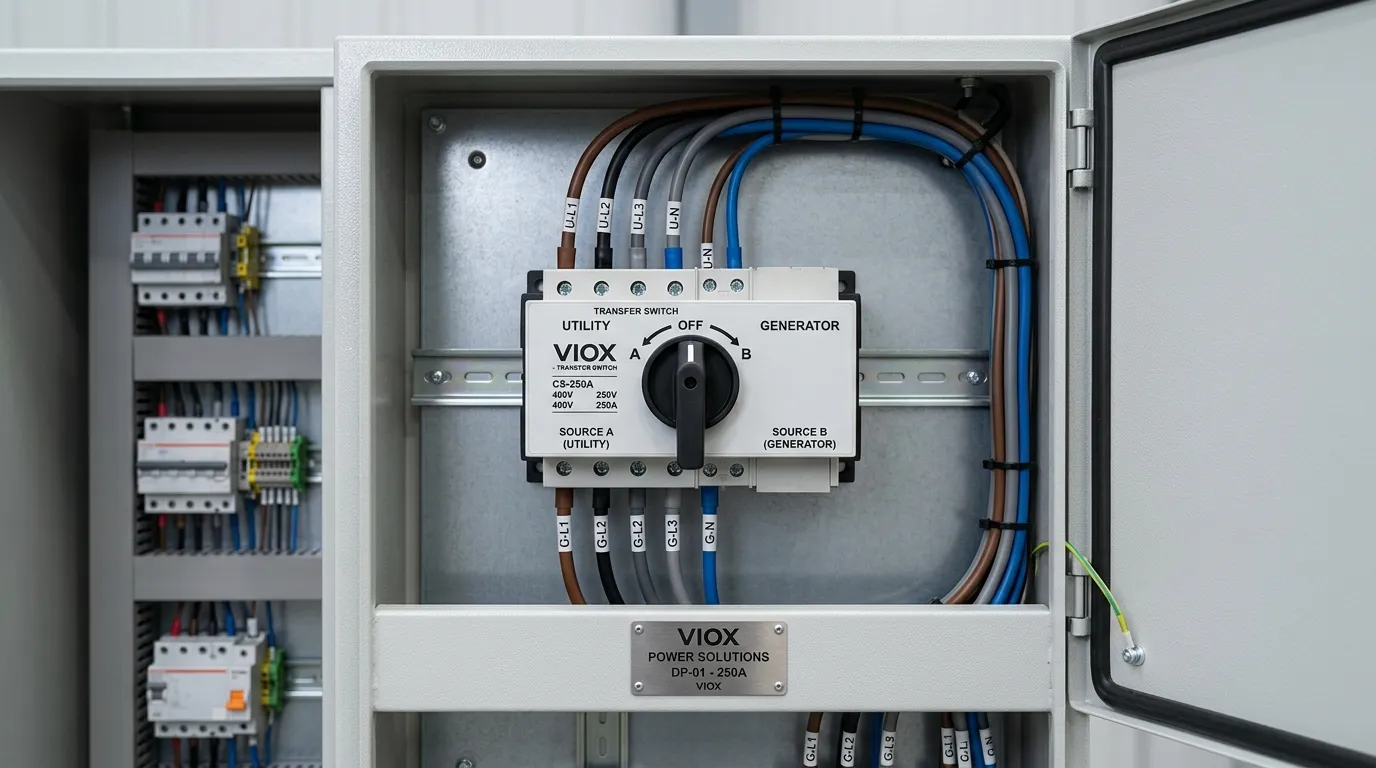
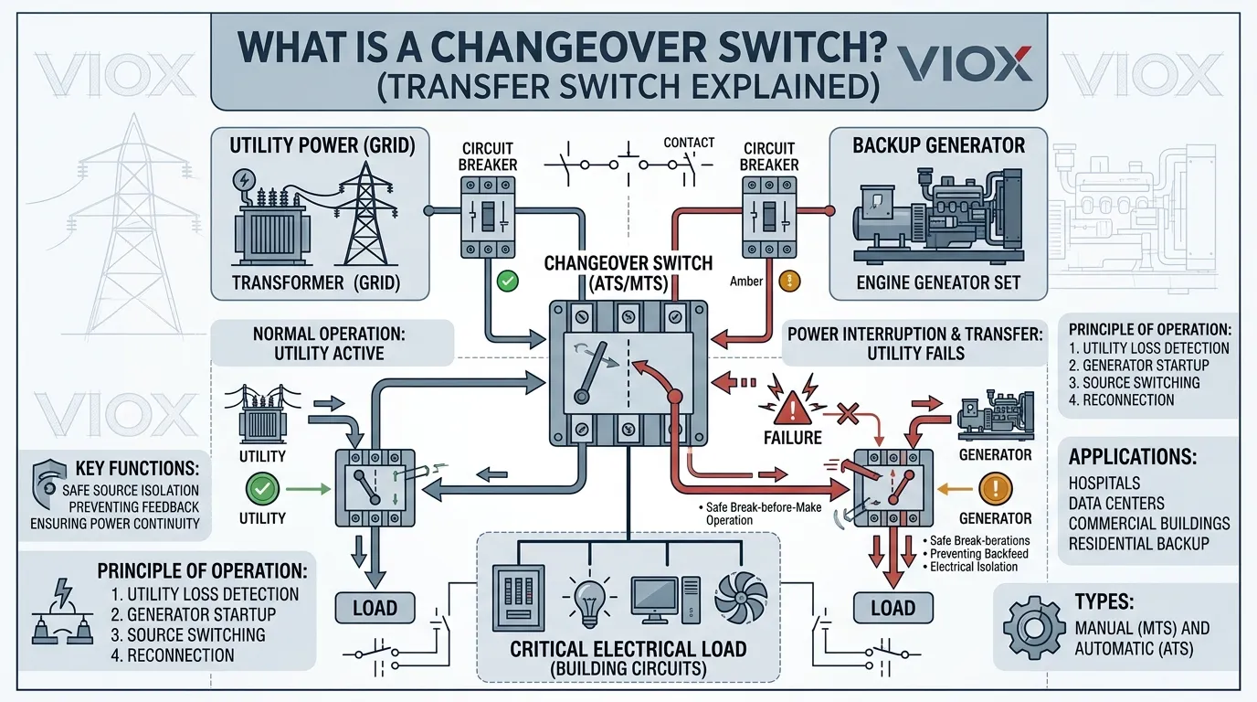
A changeover switch — also called a transfer switch in North American practice — connects a load to one of two available power sources at any given time. Its internal mechanism ensures that when one source is connected, the other is physically disconnected. That mutual exclusion is what separates a changeover switch from an ordinary switch or contactor arrangement: the device is purpose-built to prevent two live sources from meeting on the load side.
Consider a 400 V three-phase commercial building supplied by the utility grid and backed up by a 250 kVA standby diesel generator. The changeover switch sits between both sources and the distribution board. During normal operation, current flows from the grid through the switch to the load. When the grid drops below the undervoltage threshold — typically set around 85 % of nominal — the switch transfers the load to the generator. When the grid recovers and holds steady above pickup voltage for the programmed delay period, the load transfers back. At no point during this sequence are both sources connected simultaneously.
That isolation matters more than many specifiers realize. Paralleling two unsynchronized sources — even for a few cycles — can produce fault currents well above the prospective short-circuit level at the installation point, trip upstream protective devices, and push generator power back onto the utility network. A properly rated changeover switch eliminates that risk by design, which is exactly why IEC 60947-6-1 and UL 1008 treat the interlock mechanism as a primary safety function rather than an optional feature.
How Does a Changeover Switch Work?
The working principle of a changeover switch is built around a mutually exclusive contact arrangement. Three sets of terminals — source A (main supply), source B (backup), and load — connect through internal contacts that move between two stable positions. The mechanical or electrical design enforces a rule that only one source feeds the load at any instant.
Normal Operation
Under normal conditions the changeover switch rests in its preferred position. The load draws power from the primary source — usually the utility grid. The backup source terminals sit open, and the generator may be off entirely or running on standby at idle.
Detection of a Transfer Condition
A transfer condition arises when the preferred source falls outside acceptable parameters. In a manual changeover switch, the operator notices lights out (or gets a call) and walks to the panel. In an automatic changeover switch, the controller monitors source voltage and frequency continuously. Most controllers trip on sustained undervoltage — a setting between 80% and 90% of nominal is common — or complete loss of phase. IEC 60947-6-1 defines specific test sequences for verifying that the sensing function responds correctly under both gradual voltage decay and instantaneous loss conditions.
The Transfer Sequence
During transfer, the switch breaks the connection to the failed source before making the connection to the backup. This break-before-make action is the fundamental operating requirement. In most designs there is an intentional dead time between disconnecting one source and connecting the other — typically 50–100 ms for automatic units using motorized mechanisms, and effectively instantaneous (within one mechanical stroke) for rotary manual switches, though the total outage for manual transfer includes generator startup time.
IEC 60947-6-1 classifies automatic transfer switching equipment (ATSE) by transfer time: Class A for equipment that does not limit the interruption duration, Class B for medium-interruption (≤ 150 ms), and Class C for short-interruption (≤ 20 ms with stored-energy mechanisms). UL 1008, which governs the North American market, specifies comparable transfer and withstand tests but uses a different classification framework centered on total system transfer time including engine-generator start.
Once the backup source is connected and stable, the load resumes operation on the alternative supply.
Return Transfer (Retransfer)
When the original source recovers, the switch performs the same sequence in reverse. Automatic changeover switches typically include a programmable retransfer delay — 5 to 30 minutes is standard practice — to confirm the returning source is stable and avoid transferring back into a utility reclose cycle or unstable recovery. Manual units rely on the operator to confirm source health and initiate the return.
Interlock Mechanisms
In manual changeover switches, a mechanical interlock physically prevents the switch handle from engaging both positions — usually a sliding bar or cam arrangement that locks one contact set open when the other is closed. In automatic units, electrical interlocking through the controller logic is the primary barrier, often supplemented by a mechanical interlock on the contactor or switch mechanism. Some designs include a third center-off position where neither source connects, which IEC 60947-6-1 recognizes as an additional isolation state useful for maintenance procedures.
Types of Changeover Switches
The most consequential distinction in the changeover switch market is between manual and automatic operation. Getting this decision wrong means either spending on automation the project does not need, or leaving a critical load unprotected when nobody is around to flip a handle.
Manual Changeover Switch
A manual changeover switch requires an operator to physically move the switching mechanism from one position to the other. There is no controller, no voltage-sensing circuit, and no automatic start signal to the generator. The operator detects the outage, starts the backup source, confirms stable output, and turns the handle.
Typical products range from 63 A rotary switches for single-phase residential panels to 3200 A enclosed manual transfer switches for industrial distribution boards. Construction standards vary by market — IEC 60947-3 covers manual switches in international markets, while UL 1008 covers them in North America when the device is specifically listed as transfer switch equipment.
Where manual changeover switches earn their place:
- Residential generator backup where someone is normally home.
- Small commercial installations — a 30 kVA genset backing up a retail shop — where staff can respond within a few minutes.
- Basic standby systems where the load tolerates an interruption measured in minutes rather than seconds.
- Projects where the owner wants direct, visible control over the source-transfer decision.
Advantages. Fewer parts. Lower purchase price — a quality 100 A 4-pole manual changeover switch typically costs 30–50% less than an equivalent automatic unit. No control-circuit power dependency. Extremely long mechanical life, often exceeding 10,000 operations.
Limitations. Dead in the water without a person present. An outage at 2 AM on a public holiday means the load stays dark until someone arrives. For refrigeration, life-safety, server rooms, or process loads with narrow interruption tolerance, that gap is unacceptable.
Automatic Changeover Switch
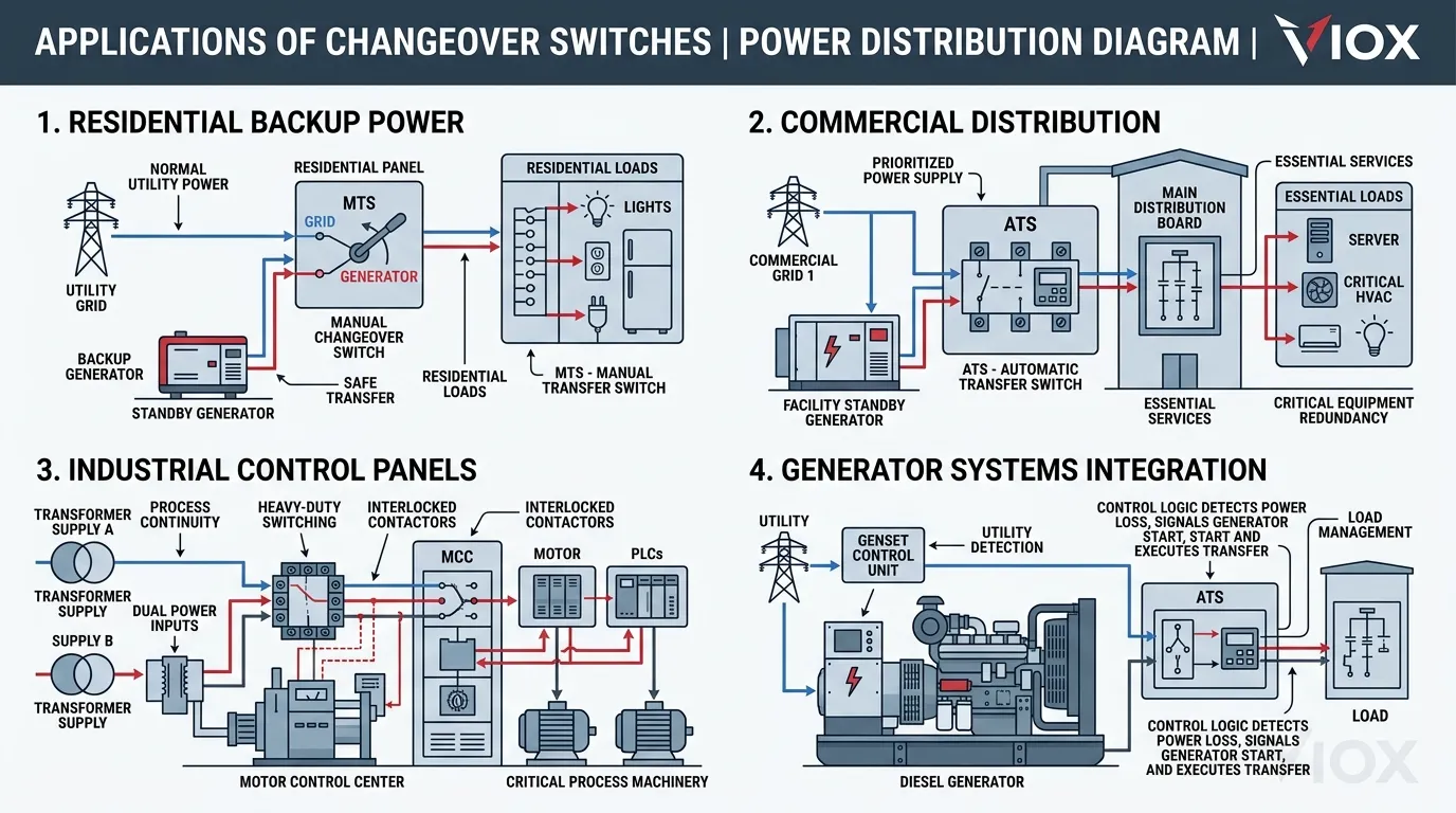
An automatic changeover switch monitors both power sources continuously and executes the transfer without human intervention. When the controller detects that the preferred source has dropped below threshold, it sends a start signal to the generator, waits for the engine to reach stable voltage and frequency (typically 10–15 seconds for a properly maintained diesel set), and then transfers the load. When the preferred source returns and holds within tolerance for the retransfer delay, the switch moves the load back and shuts down the generator.
In project specifications, product catalogs, and most international standards documentation, the automatic changeover switch is designated as automatic transfer switching equipment (ATSE) under IEC 60947-6-1, or as an automatic transfer switch (ATS) under UL 1008. The terms overlap almost completely in practice.
Where automatic changeover switches are the baseline requirement:
- Hospitals and healthcare facilities — most building codes mandate automatic transfer for life-safety and critical branch loads.
- Data centers operating at Tier II or above.
- Commercial buildings where outage cost exceeds several hundred dollars per minute.
- Industrial operations running continuous processes — a kiln, an extrusion line, a batch reactor.
- Telecom sites and infrastructure installations that may sit unattended for weeks.
- Any site where the insurance policy, the SLA, or the building code says transfer must happen without a phone call.
Advantages. Fast, unattended transfer — total outage typically under 15 seconds from utility loss to generator on load, depending on engine start time and ATSE class. Removes operator error from the transfer sequence. Integrates with generator auto-start systems, BMS, and SCADA platforms. Provides event logging for compliance and maintenance records.
Limitations. Higher unit cost, more complex control wiring, and a commissioning process that requires coordinated testing with the generator and upstream protection. The controller, voltage-sensing circuits, and motorized mechanism all require periodic functional testing — quarterly at minimum for critical installations, per most facility maintenance standards.
For a detailed side-by-side breakdown, see Manual vs. Automatic Transfer Switch.
Manual vs. Automatic Changeover Switch: Detailed Comparison
| Factor | Manual Changeover Switch | Automatic Changeover Switch |
|---|---|---|
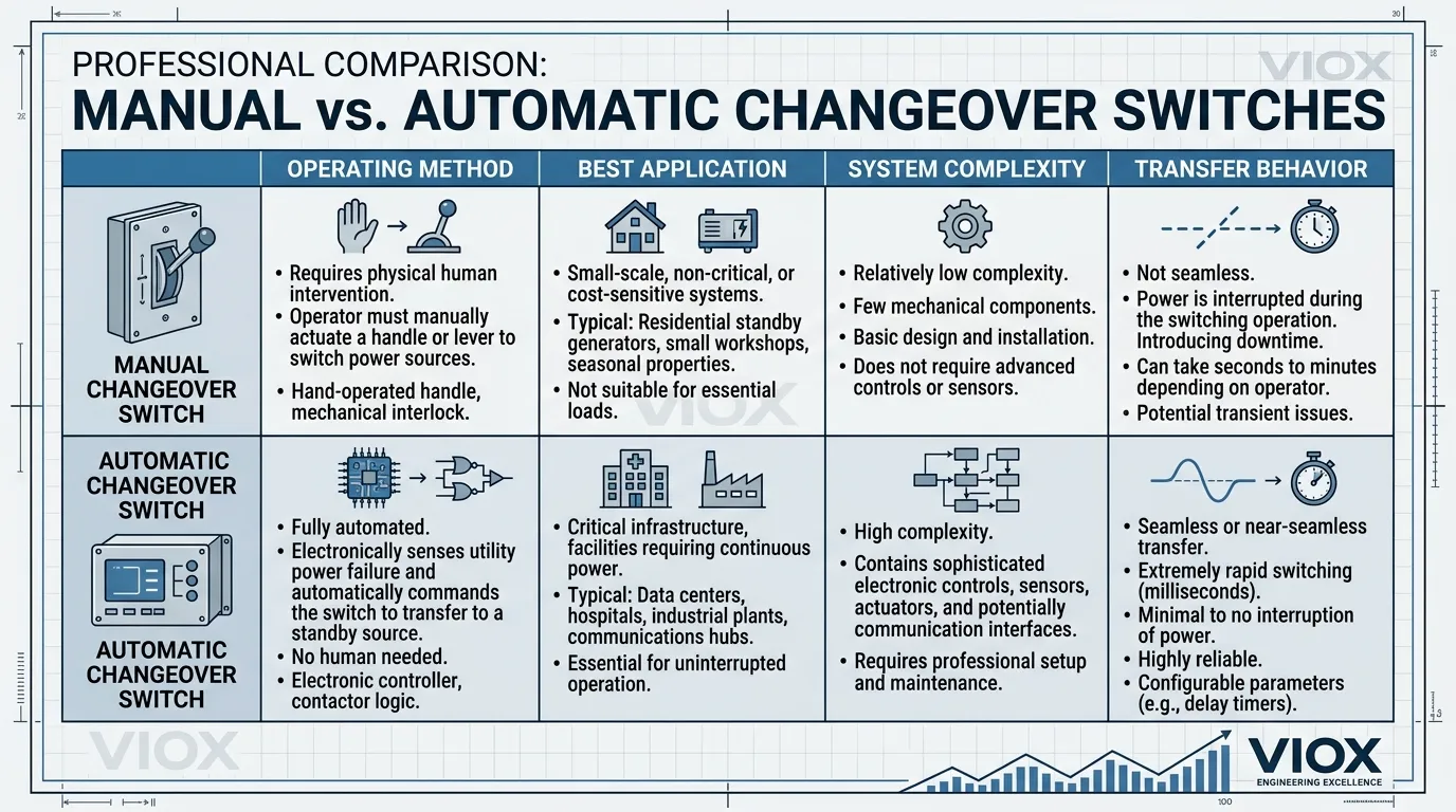
| Transfer method | Operator physically moves the handle | Controller detects failure and transfers automatically |
| Typical transfer time | 1–15 minutes (includes travel to panel, generator start, switching) | 5–15 seconds after generator reaches stable output |
| Operator required | Yes, always | No — operates unattended 24/7 |
| Typical equipment cost | Lower (fewer components) | Higher (controller, motorized mechanism, sensing circuits) |
| Installation complexity | Power wiring only | Power wiring plus control wiring, sensing circuits, and programming |
| Maintenance | Annual visual inspection, lubrication, exercise | Quarterly functional testing, calibration, annual service |
| Best fit | Non-critical loads, attended sites, budget-constrained projects | Critical loads, unattended sites, facilities requiring fast recovery |
| Mechanical life | Very long (simple mechanism, fewer wear parts) | Long, but controller and motor components add maintenance scope |
| Integration with BMS/SCADA | Not applicable | Standard feature on most modern units |
| Governing standards | IEC 60947-3, UL 1008 (manual class) | IEC 60947-6-1 (ATSE), UL 1008 (automatic class) |
Decision Framework
Choose a manual changeover switch when the load can ride through an interruption lasting several minutes, a trained person will always be available on site, the project budget favors simplicity, or the installation is a residential or small commercial backup with a sub-100 kVA generator.
Choose an automatic changeover switch when the load is essential or life-safety classified, the facility may be unoccupied during an outage, the specification or code requires transfer within a defined time window (often ≤ 10 seconds), or the system must feed status data to centralized monitoring.
Changeover Switch Applications
Residential Backup Power
The generator changeover switch is one of the most common residential electrical upgrades in outage-prone areas. A typical installation connects the utility supply and a portable or permanently installed generator to a changeover switch mounted adjacent to the main distribution board. Selected circuits — or the entire house, depending on generator capacity — feed through the switch so the homeowner can transfer to generator power when the grid drops.
Manual changeover switches dominate this segment. A 63 A or 100 A 4-pole manual unit handles most single-phase residential loads at a fraction of the cost of an automatic system. Homes with medical equipment, home offices running revenue-generating operations, or whole-house standby generators increasingly spec automatic units — particularly where the homeowner travels frequently and the house may be unoccupied during a storm.
Commercial Buildings
Offices, retail spaces, hotels, and mixed-use buildings use changeover switches to maintain power to essential systems: emergency lighting, fire alarm panels, elevators, IT closets, point-of-sale infrastructure, and HVAC controls. In most jurisdictions — IEC, NEC, and regional building codes alike — life-safety loads on the emergency branch require automatic transfer. Non-essential loads may sit behind a separate manual unit on a lower-priority panel.
A mid-rise commercial building might have a 400 A automatic changeover switch on the essential-load board feeding emergency lighting and fire systems, plus a 630 A manual unit on the standby board serving HVAC and general power. That split keeps the automatic equipment where it is legally required and controls cost on the rest.
Industrial Facilities
Manufacturing plants, processing facilities, and warehouses frequently operate with dual-feed utility arrangements or dedicated standby generators rated from 500 kVA to several MVA. Industrial changeover switches in these environments handle higher current ratings — 800 A, 1600 A, 3200 A — and must coordinate with upstream protective devices, downstream motor loads, and sometimes capacitor banks that create re-energization transients.
The choice between PC class and CB class construction becomes critical at these ratings. PC class (power contactor) devices built to IEC 60947-6-1 are purpose-designed for transfer duty and typically offer higher mechanical endurance. CB class devices use circuit breakers as the switching elements, adding built-in overcurrent protection but with different contact wear characteristics.
Telecom and Data Infrastructure
Cell towers, switching centers, and data halls demand the highest power continuity levels. Automatic changeover switches in these installations often feature redundant controllers, bypass isolation for maintenance without load interruption, and Modbus/SNMP communication interfaces for NOC-level remote monitoring. Transfer time requirements at Tier III and Tier IV data centers may be specified in cycles (≤ 4 cycles at 50 Hz = 80 ms), pushing the design toward stored-energy or static transfer mechanisms rather than conventional motorized ATSE.
Hybrid and Multi-Source Systems
Solar-plus-storage installations, microgrids, and facilities with both generator and inverter backup may need changeover switches managing more than two sources — or managing two sources with tighter transition constraints than a standard open-transition device can provide. In these arrangements the changeover function becomes part of a broader power-management architecture that may include open and closed transition transfer modes, where closed transition briefly parallels the two sources under synchronized conditions before breaking the original connection.
Pole Configuration: Matching the Changeover Switch to the System
Changeover switches are manufactured in 2-pole, 3-pole, and 4-pole configurations. The correct pole count depends on the electrical system and the earthing arrangement — not simply the number of phases.
| Configuration | Typical Application |
|---|---|
| 2-pole | Single-phase systems where neutral is not switched |
| 3-pole | Three-phase systems where neutral is common and not switched |
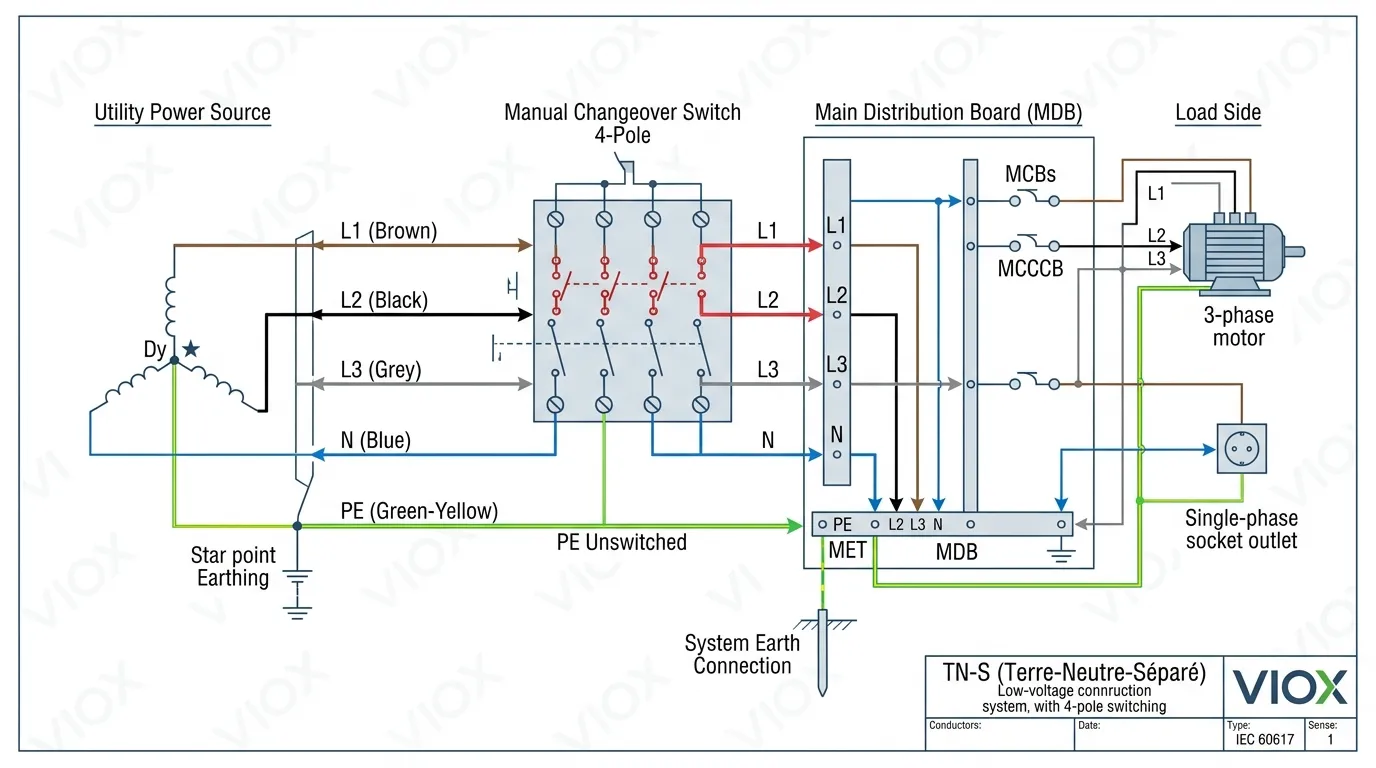
| 4-pole | Three-phase systems where neutral must be switched (standard in TN-S, IT, and certain TT earthing arrangements) |
Choosing the wrong pole configuration is one of the most persistent specification errors in source-transfer design. A three-phase system does not automatically call for a 3-pole changeover switch. If the earthing arrangement, the generator neutral bonding scheme, or local code requires switched neutral — and in most TN-S systems with separately derived generator sources, it does — a 4-pole unit is mandatory. Failing to switch the neutral in these systems creates a parallel neutral path between sources, which can cause circulating currents, nuisance RCD tripping, and unreliable ground-fault detection.
For a detailed phase-and-pole selection walkthrough, see Single Phase vs. Three Phase ATS.
How to Choose the Right Changeover Switch
Selecting the right changeover switch for a project means working through a series of technical and operational decisions in the correct sequence. Skip a step, and the product either will not fit the installation or will not perform as expected under real fault conditions.
Step 1: Define the Source Arrangement
Identify exactly which two sources the switch must manage. Utility plus generator is the dominant pair, but the sources could be two independent utility feeders (common in dual-bus industrial substations), a utility feed and an inverter, or a generator and a UPS bypass output. The source characteristics — nominal voltage, frequency, phase count, available fault current — set the electrical boundaries for the switch.
Step 2: Decide Between Manual and Automatic Operation
Almost always the first major commercial decision. Review the load’s maximum tolerable interruption time, the availability of trained operators, the building code requirements for the load classification, and the project budget. On many projects, this single decision cuts the product shortlist in half.
Step 3: Match Electrical Ratings
Confirm that the changeover switch is rated for the system voltage (e.g., 230/400 V, 277/480 V), the maximum continuous current at the point of installation, the prospective short-circuit current (Isc) with appropriate withstand rating (Icw for ATSE per IEC 60947-6-1, or short-circuit current rating per UL 1008), and the correct number of poles. Undersizing creates a safety hazard. Oversizing wastes budget and panel space — a 1600 A switch where 630 A would suffice is not conservative engineering, it is poor specification.
Step 4: Evaluate Load Characteristics
Motor-heavy loads, capacitor banks, and non-linear loads (VFDs, large UPS, LED driver arrays) impose transient inrush and harmonic demands that the changeover switch must withstand. Verify the product’s making capacity (peak closing current) and breaking capacity against the actual load profile, not just the steady-state thermal rating. IEC 60947-6-1 specifies dedicated test sequences for motor loads, and the switch datasheet should confirm rated values under these conditions.
Step 5: Consider Transition Type
Most changeover switches use open transition — break-before-make — which is the simplest and most common approach. Some applications benefit from closed transition (make-before-break), where the two sources are briefly paralleled under synchronized conditions (typically for 100 ms or less) before the original source disconnects. Closed transition requires frequency-matched sources, synchronism-check relaying, and additional protective logic. It is standard practice on large data center and healthcare campus projects where even sub-second interruptions disrupt sensitive load processes. Refer to our open vs. closed transition guide for detailed selection criteria.
Step 6: Verify Standards and Certification
For international markets, confirm the changeover switch carries IEC 60947-6-1 type-test certification from an accredited laboratory (e.g., KEMA, CESI, TÜV). For North American installations, require UL 1008 listing or CSA C22.2 No. 178 certification. The product should also comply with the relevant assembly standard — IEC 61439-1/-2 if installed in a type-tested switchboard, or UL 891 for North American switchboard applications. Do not accept manufacturer self-declarations without supporting type-test reports ; the standards exist precisely to validate performance claims under fault and endurance conditions.
Step 7: Review Installation and Environmental Conditions
Check available panel space, the enclosure IP rating required for the environment (indoor clean, outdoor, dusty, humid, washdown), cable entry positions, and service access clearances mandated by local code (IEC 61439 or NEC 110.26). A switch that satisfies every electrical parameter but cannot physically be installed, accessed, or maintained is not the right switch.
Step 8: Align With the Project’s Transfer Philosophy
Some facility owners prioritize simplicity and visible operator control — a straightforward handle they can see in the down position. Others prioritize speed, automation, and remote visibility with full BMS integration. The changeover switch should match the operating philosophy of the building and the maintenance team that will own the system for the next two decades.
Installation Essentials for Changeover Switches
Professional Installation Is Non-Negotiable
A changeover switch sits at the boundary between two live power sources. Incorrect wiring, a missing interlock, or improper grounding can create backfeed onto the utility network, arc flash hazards for maintenance personnel, and equipment damage from unsynchronized paralleling. Installation must be performed by a licensed electrician experienced with source-transfer equipment and familiar with the applicable local code — whether that is the IEC/BS wiring regulations, the NEC, the Australian AS/NZS 3000, or another national standard.
Key Installation Steps
The general sequence: de-energize both sources and apply lockout/tagout, mount the switch in the designated enclosure or panel position per manufacturer clearance requirements, terminate the utility (source A) supply cables, terminate the generator or backup (source B) supply cables, terminate the load output cables, install control wiring for automatic units (generator start/stop, voltage sensing, communication bus), establish earthing and bonding per the system earthing arrangement (TN-S, TN-C-S, TT, IT), and commission with a full transfer test in both directions — including verifying interlock operation by deliberately attempting to close both sources simultaneously.
Critical Safety Points
Backfeed prevention. The changeover switch must make it mechanically and electrically impossible for generator power to feed back onto the utility network. This is a code requirement in every major jurisdiction and a primary concern for utility companies and lineworkers. UL 1008 and IEC 60947-6-1 both include interlock verification as a mandatory type-test element.
Neutral handling. In 4-pole configurations, verify that the neutral contacts operate in the correct overlap sequence relative to the phase contacts. IEC 60947-6-1 Annex H provides guidance on neutral switching sequences. Incorrect neutral timing can create transient overvoltages or, worse, a floating neutral condition that exposes single-phase loads to line-to-line voltage.
Grounding. The equipment grounding conductor must be continuous and unbroken through the switch assembly. Do not rely on the enclosure chassis or mounting hardware as the sole ground path — use a dedicated bonding jumper or terminal.
Labeling. Mark the switch with source identification (SOURCE A: UTILITY, SOURCE B: GENERATOR), operating instructions for manual units, emergency contact information, and any interlock or lockout requirements. In an emergency, the person operating the switch may not be the person who normally manages the electrical system.
Maintenance and Troubleshooting
Preventive Maintenance Schedule
| Interval | Manual Changeover Switch | Automatic Changeover Switch |
|---|---|---|
| Monthly | Visual check for corrosion, loose hardware, signs of overheating | Visual check plus controller status LED/display review |
| Quarterly | Exercise the switch through a full transfer cycle under reduced load | Full functional test: simulate outage, verify auto-start signal, transfer, retransfer, and generator cooldown/shutdown |
| Annually | Torque-check all connections per manufacturer spec, lubricate mechanism, inspect contacts for pitting or discoloration | All quarterly tasks plus controller calibration, contact resistance measurement (milliohm meter), thermographic scan of connections, and full-load transfer test |
Common Issues and Solutions
Switch handle stiff or difficult to operate (manual units). Corrosion ingress, dried lubricant, or mechanical binding from misalignment after years of thermal cycling. Strip down per the manufacturer’s service manual, clean contact pivot points, re-lubricate with the specified grease (not WD-40), and check for physical obstructions or enclosure distortion.
Automatic switch fails to transfer during a real outage. Check controller power supply — many ATSE controllers draw power from the source they are monitoring, and if that source has failed the controller may be dead. Verify voltage-sensing connections at both source terminals. Confirm the generator start signal reaches the engine controller. Review pickup/dropout voltage settings — if someone tightened the dropout threshold to 90% to solve a nuisance-transfer complaint, the controller may not recognize a brownout at 88% as a transfer condition. The most frequent root cause in field investigations is a broken sensing wire or a blown control fuse that went undetected between test cycles.
Nuisance transfers on automatic units. The switch transfers to generator during brief voltage dips that do not actually warrant a transfer — a compressor starting on a neighboring circuit, a utility reclose event, or a capacitor switching transient. Widen the dropout time delay (2–5 seconds is common for non-critical loads) or narrow the voltage dropout threshold. Confirm that the sensing input has appropriate filtering and is not picking up electrical noise from VFDs or switching power supplies sharing the same panel.
Arcing or discoloration on contacts. Indicates undersized contacts for the actual load (common when motor inrush was not accounted for), excessive make/break operations under load, or contacts at end of electrical life. Measure contact resistance with a DLRO (digital low-resistance ohmmeter) — if resistance exceeds the manufacturer’s published limit (typically 50–200 µΩ depending on rating), replace the contact assembly. On large-frame units, contact replacement is a field-serviceable operation; on smaller units, it may require factory reconditioning.
Changeover Switch vs. Transfer Switch
In everyday usage, changeover switch and transfer switch describe the same device: a switch that moves a load between two power sources with mechanical or electrical interlock preventing simultaneous connection.
The terminology splits along geographic and standards lines. Changeover switch is prevalent in IEC-standard markets — Europe, the Middle East, Africa, Asia-Pacific, and most of Latin America. Transfer switch dominates in North American practice, anchored by UL 1008 terminology and NEC Article 700/701/702 language. The IEC standards themselves use the designation automatic transfer switching equipment (ATSE) rather than either colloquial term.
What matters for specification is not the label on the nameplate but the device’s rated voltage, continuous current rating, short-circuit withstand, pole configuration, transition type (open or closed), transfer time class, and certification to the applicable standard. A UL 1008-listed transfer switch and an IEC 60947-6-1-certified changeover switch performing the same function are, for engineering purposes, equivalent devices validated through different but comparable test regimes.
Common Selection Mistakes to Avoid
Treating all changeover switches as interchangeable. A manual 63 A 2-pole switch for a single-phase home and an automatic 63 A 4-pole ATSE with integrated controller serve entirely different applications. Same current number, different universe.
Selecting on current rating alone. The changeover switch must also match system voltage, phase configuration, pole count, short-circuit withstand (Icw or SCCR), and transition type. Current rating is necessary but nowhere near sufficient.
Ignoring neutral-switching requirements. In TN-S systems with a separately derived generator source, failing to switch the neutral creates a parallel path that causes circulating currents, nuisance RCD/GFCI tripping, and unreliable earth-fault detection. This is the single most common engineering error in source-transfer design, and it surfaces after commissioning when it is expensive to fix.
Specifying manual operation for an unattended site. If nobody will be on site to operate the switch — a cell tower, a pump station, a warehouse on a Sunday — the transfer will not happen. Match the operating method to actual staffing patterns, not to budget aspirations.
Overlooking maintenance access. A changeover switch installed behind a cable tray, above a false ceiling, or in a panel with 150 mm clearance to the adjacent wall will be neglected. IEC 61439 and NEC 110.26 prescribe minimum working clearances for a reason — respect them during layout, not as an afterthought during commissioning.
Accepting products without accredited type-test certification. A changeover switch that has not been type-tested to IEC 60947-6-1 or listed to UL 1008 by an independent laboratory is an unknown quantity under fault conditions. For equipment sitting between two power sources and protecting against backfeed, “unknown” is not an acceptable risk class.
Conclusion
A changeover switch is the device responsible for moving a load safely between two power sources. It sits at the heart of every generator backup system, every dual-feed distribution arrangement, and every essential-load panel where source continuity matters. Getting the selection right means understanding the source pair, choosing between manual and automatic operation, matching electrical ratings and pole configuration to the system, verifying compliance with IEC 60947-6-1 or UL 1008, and aligning the product with how the facility actually operates day-to-day.
Manual changeover switches earn their place where simplicity, low cost, and direct operator control are the priorities. Automatic changeover switches are the clear choice where the load is critical, the site may be unattended, or the code and the client both demand fast, hands-free transfer.
The right starting point for any selection decision is a single practical question: How should this load move between its two sources, and how quickly does that transfer need to happen?
FAQ
What is a changeover switch?
A changeover switch is an electrical device that transfers a load between two power sources — typically a utility supply and a generator — while preventing both sources from being connected to the load at the same time. It provides safe, controlled source transfer during outages, maintenance, or planned switching events. The device is governed by IEC 60947-6-1 (international) and UL 1008 (North America).
How does a changeover switch work?
A changeover switch uses a mutually exclusive contact arrangement to connect the load to one source at a time. When the connected source fails or a transfer is initiated, the switch disconnects the current source and then connects the alternative. A mechanical or electrical interlock — validated as a primary safety function under both IEC 60947-6-1 and UL 1008 — prevents both sources from being connected simultaneously.
What are the main types of changeover switches?
The two main types are manual changeover switches, which require an operator to move the switch handle, and automatic changeover switches (designated as ATSE under IEC 60947-6-1), which use a controller to detect source failure and execute the transfer without human intervention.
What is the difference between a changeover switch and a transfer switch?
Functionally identical. “Changeover switch” is the predominant term in IEC-standard markets worldwide, while “transfer switch” is the standard designation in North American (UL/NEC) practice. The IEC standards use the formal designation “automatic transfer switching equipment (ATSE).”
Where are changeover switches used?
Residential generator backup systems, commercial buildings, industrial facilities, hospitals, data centers, telecom sites, and any installation where a load must be transferred between two power sources safely and reliably.
Can a changeover switch be used in a three-phase system?
Yes. Changeover switches are available in 2-pole, 3-pole, and 4-pole configurations for single-phase and three-phase systems. The correct pole count depends on the phase arrangement and whether the neutral must be switched — which is determined by the system earthing arrangement (TN-S, TN-C-S, TT, IT) and local code requirements.
When should I choose an automatic changeover switch over a manual one?
When the load is critical or life-safety classified, the facility may be unoccupied during an outage, the specification requires transfer within a defined time window (often ≤ 10 seconds per IEC 60947-6-1 Class B), or the system must integrate with BMS/SCADA platforms.
How long does a changeover switch last?
A quality unit with proper maintenance typically operates reliably for 15 to 25 years. Manual units tend to have longer mechanical life due to fewer electronic components. Automatic units may require controller board or motor mechanism replacement during their service life, depending on the number of accumulated operations versus the manufacturer’s rated mechanical and electrical endurance.
What size changeover switch do I need?
The switch must be rated for the system voltage and the maximum continuous load current at the installation point. It must also carry a short-circuit withstand rating (Icw per IEC 60947-6-1 or SCCR per UL 1008) appropriate for the available fault current. Have a licensed electrician perform a load analysis and verify fault levels before sizing.
Can I use a changeover switch with solar panels or battery storage?
Yes. In hybrid and multi-source systems, changeover switches manage transfer between utility power, inverter output, battery storage, or generator backup. These installations may require additional control logic and, in some cases, closed-transition transfer capability to avoid disrupting sensitive loads during source handoff.
Is it safe to install a changeover switch myself?
No. A changeover switch sits between two live power sources and involves work on main distribution circuits. Incorrect installation can create lethal backfeed, arc flash hazards, and code violations. Use a licensed electrician with experience in source-transfer equipment.
How often should I test my changeover switch?
Manual units: exercise through a full transfer cycle at least quarterly, with an annual connection torque check, contact inspection, and lubrication. Automatic units: full functional test monthly — including simulated outage, generator start, transfer, retransfer, and shutdown sequence — with comprehensive annual servicing including contact resistance measurement, thermographic scanning, and controller calibration.
What standards apply to changeover switches?
The primary international standard is IEC 60947-6-1, which covers automatic transfer switching equipment (ATSE) including test requirements for electrical endurance, short-circuit withstand, and transfer time classification. In North America, UL 1008 covers transfer switch equipment. Manual changeover switches used outside of a dedicated transfer-switch listing may also fall under IEC 60947-3 (switch-disconnectors). Assemblies containing changeover switches should comply with IEC 61439 (international) or UL 891 (North America).
