اس صفحے پر
لو-وولٹیج موٹر پروٹیکشن ایک مربوط برقی نظام ہے، نہ کہ صرف ایک سرکٹ بریکر۔ شارٹ سرکٹ سے بچاؤ کا آلہ شدید فالٹ انرجی کو محدود کرتا ہے، اوورلوڈ فنکشن مسلسل تھرمل تناؤ سے تحفظ فراہم کرتا ہے، کونٹیکٹر نارمل سوئچنگ کا کام کرتا ہے، مانیٹرنگ ریلے سپلائی کے حالات کی نگرانی کرتے ہیں، اور ایمبیڈڈ سینسرز ایسی حرارت کا پتہ لگاتے ہیں جو لائن-کرنٹ کی پیمائش سے چھوٹ سکتی ہے۔ درست آرکیٹیکچر کا انحصار موٹر، اسٹارٹنگ کے طریقہ کار، ڈرائیون لوڈ، ماحول، اور ناکامی کے نتائج پر ہوتا ہے۔.
انجینئرنگ کی حدود: یہ گائیڈ صنعتی اور کمرشل برقی نظاموں میں لو-وولٹیج AC موٹرز کے پروٹیکشن آرکیٹیکچر کا احاطہ کرتی ہے۔ یہ ماڈل کے لحاظ سے مخصوص وائرنگ یا یونیورسل ٹرپ سیٹنگز فراہم نہیں کرتی ہے۔ حتمی ڈیوائس کے انتخاب اور سیٹنگز کے لیے موٹر کا ڈیٹا، دستیاب فالٹ کرنٹ، اسٹارٹنگ اسٹڈی، مینوفیکچرر کے کروز، کوآرڈینیشن ڈیٹا، تنصیب کے حالات، اور قابل اطلاق مقامی قوانین درکار ہوتے ہیں۔.
چھ حفاظتی تہیں
ایک مفید ڈیزائن ان چھ فنکشنز کو الگ کرنے سے شروع ہوتا ہے جنہیں اکثر خلط ملط کر دیا جاتا ہے:
| حفاظتی تہہ | بنیادی ذمہ داری | عام آلات | اہم حد |
|---|---|---|---|
| شارٹ سرکٹ تحفظ | ہائی فالٹ کرنٹ کو منقطع کرنا اور برانچ سرکٹ کی حفاظت کرنا | فیوز، MCCB، جہاں مناسب ہو وہاں MCB، MPCB/MPSD | صرف شارٹ سرکٹ ڈیوٹی کے لیے منتخب کردہ ڈیوائس موٹر-اوورلوڈ سے مناسب تحفظ فراہم نہیں کر سکتی ہے |
| موٹر اوورلوڈ پروٹیکشن | موٹر کو مسلسل اوور کرنٹ اور تھرمل اوورلوڈ سے محفوظ رکھیں۔ | تھرمل یا الیکٹرانک اوورلوڈ ریلے، MPCB، موٹر پروٹیکشن ریلے | کرنٹ پر مبنی تحفظ، زیادہ گرم ہونے (overheating) کے ہر ذریعہ کا پتہ نہیں لگا سکتا۔ |
| سوئچنگ اور کنٹرول | موٹر کو نارمل آپریشن سے اسٹارٹ، اسٹاپ، انٹرلاک اور آئسولیٹ کریں۔ | کونٹیکٹر، موٹر اسٹارٹر، کنٹرول ریلے | ایک کونٹیکٹر شارٹ سرکٹ سے بچاؤ کا آلہ نہیں ہے۔ |
| سپلائی کی حالت کی نگرانی | فیز کے ضائع ہونے، فیز کی ترتیب، وولٹیج کے عدم توازن، اوور وولٹیج، یا انڈر وولٹیج کا پتہ لگائیں | تھری فیز مانیٹرنگ ریلے، ملٹی فنکشن موٹر ریلے | ایک وولٹیج ریلے براہ راست وائنڈنگ کے درجہ حرارت یا مکینیکل لوڈ کی پیمائش نہیں کرتا ہے |
| براہ راست تھرمل تحفظ | وائنڈنگ یا کسی اور محفوظ مقام پر اصل درجہ حرارت کا پتہ لگائیں | PTC تھرمسٹر، RTD، تھرموسٹیٹ، ٹمپریچر ریلے | سینسر کا مقام اور موٹر کی ساخت اس بات کا تعین کرتی ہے کہ اصل میں کیا پیمائش کی جا رہی ہے |
| کنڈیشن اور پروسیس مانیٹرنگ | موٹر یا چلنے والے آلات کو نقصان پہنچانے سے پہلے مکینیکل یا پروسیس کی صورتحال کا پتہ لگائیں | وائبریشن، بیئرنگ کا درجہ حرارت، انڈر کرنٹ، انڈر پاور، بہاؤ، یا پریشر کی نگرانی | یہ فنکشنز برقی تحفظ میں اضافہ کرتے ہیں؛ یہ برانچ سرکٹ پروٹیکشن کی جگہ نہیں لیتے۔ |
IEC 60947-4-1:2023 الیکٹرو مکینیکل کونٹیکٹرز اور موٹر سٹارٹرز کا احاطہ کرتا ہے، بشمول موٹر پروٹیکٹو سوئچنگ ڈیوائسز۔ IEC 60034-11:2020 الگ سے ان تھرمل پروٹیکٹرز اور ڈیٹیکٹرز کو مخاطب کرتا ہے جو اہل انڈکشن موٹرز میں شامل یا ان پر نصب ہوتے ہیں۔ یہ علیحدگی عملی ڈیزائن کے اصول کی عکاسی کرتی ہے: کرنٹ سینسنگ سٹارٹر کا جزو اور درجہ حرارت کا سینسر ایک ہی خرابی کے میکانزم کا مشاہدہ نہیں کرتے.
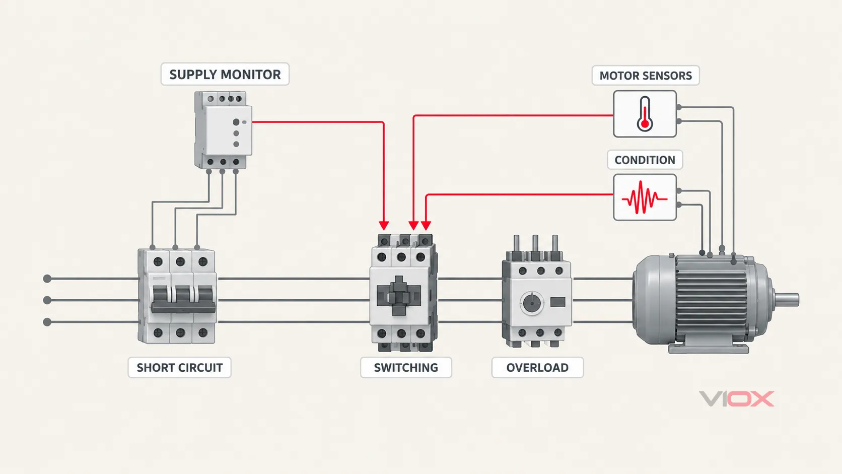
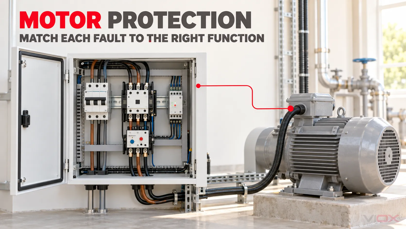
صرف تصوراتی فنکشنل آرکیٹیکچر۔ لائنیں سینسنگ اور حفاظتی تعلقات کی نشاندہی کرتی ہیں؛ یہ ٹرمینل لیول کی انسٹالیشن وائرنگ نہیں ہیں۔.
شروعات موٹر اور پروسیس سے کریں، نہ کہ بریکر سے
تحفظ کے آلات کا انتخاب کرنے سے پہلے، موٹر کی تھرمل حدود اور اس کے آپریٹنگ ڈیوٹی دونوں کو بیان کرنے کے لیے کافی معلومات جمع کریں۔.
موٹر کا برقی ڈیٹا
کم از کم درج ذیل ریکارڈ کریں:
- ریٹیڈ وولٹیج، فریکوئنسی، پاور، کرنٹ، رفتار، اور فیزز کی تعداد؛;
- کارکردگی اور پاور فیکٹر جہاں برقی نظام کے حساب کتاب کے لیے ضروری ہو؛;
- سروس فیکٹر یا قابلِ قبول لوڈنگ کی معلومات جہاں لاگو ہو؛;
- انسولیشن اور ٹمپریچر کلاس؛;
- اسٹارٹنگ کا طریقہ اور متوقع اسٹارٹنگ کرنٹ؛;
- قابلِ قبول ایکسلریشن کا وقت، ہاٹ-اسٹارٹ اور کولڈ-اسٹارٹ کی حدود، اور فی گھنٹہ اسٹارٹس کی تعداد؛;
- آیا PTC تھرمسٹرز، ریزسٹنس ٹمپریچر ڈیٹیکٹرز (RTDs)، تھرموسٹیٹس، یا بیئرنگ سینسرز نصب ہیں؛;
- آیا موٹر لائن فیڈ، سافٹ اسٹارٹر فیڈ، یا انورٹر فیڈ ہے۔.
نیم پلیٹ کرنٹ ایک ضروری ان پٹ ہے، لیکن یہ مکمل حفاظتی تفصیلات نہیں ہے۔ ایک ہی ریٹیڈ کرنٹ والی دو موٹروں کے ایکسلریشن کے اوقات، تھرمل صلاحیت، لوڈ انرشیا، کولنگ، اور اسٹارٹ کی قابل قبول فریکوئنسی مختلف ہو سکتی ہے۔.
ڈرائیون لوڈ کا رویہ
پمپ، پنکھا، کنویئر، کرشر، کمپریسر، اور ہوسٹ ایک جیسا خطرہ پیش نہیں کرتے۔ تعین کریں:
- اسٹارٹنگ ٹارک اور لوڈ انرشیا؛;
- آیا مکینیکل جام یا لاکڈ روٹر کا امکان ہے؛;
- آیا انڈر لوڈ ٹوٹے ہوئے بیلٹ، خشک چلنے والے پمپ، یا پروسیس میٹریل کے ضیاع کی نشاندہی کرتا ہے؛;
- آیا تیزی سے ریورسنگ، جاگنگ، پلگنگ، یا بار بار سائیکلنگ ہوتی ہے؛;
- آیا موٹر کم رفتار پر انرجائز رہ سکتی ہے اور اپنی کولنگ کھو سکتی ہے؛;
- آیا برقی تحفظ کے عمل سے پہلے کسی پروسیس انٹرلاک کو موٹر روک دینی چاہیے۔.
تنصیب اور ماحول
محیط درجہ حرارت، بلندی، انکلوژر وینٹیلیشن، دھول، نمی، کروسیو ماحول، ہارمونکس، وولٹیج کا معیار، کیبل کی لمبائی، اور گروپنگ آپریٹنگ درجہ حرارت یا حفاظتی ڈیوائس کے ردعمل کو تبدیل کر سکتے ہیں۔ ریفرنس حالات میں کیٹلاگ کی کارکردگی فرض کرنے کے بجائے اصل آلات کے لیے اصلاح اور تنصیب کے اصولوں کا اطلاق کریں۔.
ناکامی کا نتیجہ
صرف موٹر کی پاور اس کی اہمیت کا تعین نہیں کرتی۔ ایک چھوٹا لیوبری کیشن پمپ، کولنگ فین، یا سیل-آئل موٹر ایک بہت بڑی مشین کے لیے ضروری ہو سکتے ہیں۔ درجہ بندی کریں کہ اگر موٹر رک جائے، شروع ہونے میں ناکام ہو جائے، غیر متوقع طور پر دوبارہ شروع ہو جائے، یا غیر معمولی حالت میں چلتی رہے تو کیا ہوگا:
- اسٹینڈرڈ ڈیوٹی: محدود پروسیس کا نتیجہ اور سیدھی سادی تبدیلی۔.
- اہم ڈیوٹی: بامعنی پیداواری نقصان، مشکل رسائی، یا چلنے والے آلات کو نقصان۔.
- نازک ڈیوٹی: حفاظت، بڑے عمل کا تسلسل، مرمت کی زیادہ لاگت، یا ثانوی نقصان کا انحصار قابل اعتماد آپریشن پر ہے۔.
یہ درجہ بندی طے کرتی ہے کہ آیا ڈیزائن کو صرف ٹرپ کرنا چاہیے، ٹرپ ہونے سے پہلے الارم دینا چاہیے، اضافی سینسنگ فراہم کرنی چاہیے، واقعات کو ریکارڈ کرنا چاہیے، یا کنٹرول سسٹم کے ساتھ ضم ہونا چاہیے۔.
فالٹ-ٹو-فنکشن موٹر پروٹیکشن میٹرکس
درج ذیل میٹرکس ڈیزائن کا مرکز ہے۔ یہ اس بات کی نشاندہی کرتا ہے کہ فنکشن انجام دینے والے ڈیوائس کو منتخب کرنے سے پہلے کن چیزوں کا پتہ لگانا ضروری ہے۔.
| غیر معمولی حالت | کیا مشاہدہ کیا جانا چاہیے | حفاظتی ردعمل | عام نفاذ | ڈیزائن کی حد |
|---|---|---|---|---|
| شارٹ سرکٹ | بہت زیادہ فیز کرنٹ یا فالٹ کرنٹ | فوری تعطل | فیوز، سرکٹ بریکر، MPCB/MPSD | وولٹیج ریٹنگ، بریکنگ کیپیسٹی، لیٹ-تھرو انرجی، اور کوآرڈینیشن کی تصدیق کریں |
| سسٹینڈ اوور لوڈ | کرنٹ اور وقت، بعض اوقات تھرمل ماڈل | نقصان دہ تھرمل تناؤ جمع ہونے سے پہلے ٹرپ کریں | تھرمل/الیکٹرانک اوورلوڈ ریلے، MPCB، موٹر ریلے | موٹر ڈیوٹی اور ٹرپ کلاس کو میچ کریں؛ محض ٹرپنگ سے بچنے کے لیے اوور سائز نہ کریں |
| اسٹارٹ ہونے میں ناکامی یا طویل ایکسلریشن | کرنٹ زیادہ رہتا ہے جبکہ رفتار وقت پر نہیں بڑھ پاتی | ٹرپ یا اسٹارٹ کو منسوخ کرنا | الیکٹرانک اوورلوڈ یا موٹر ریلے؛ اسٹارٹر لاجک | ہائی انرشیا اسٹارٹ اور اسٹال کے درمیان فرق کریں |
| لاکڈ روٹر یا مکینیکل جام | اسٹارٹنگ کے بعد ہائی کرنٹ، کم رفتار، یا غیر معمولی ٹارک | موٹر کی تھرمل حد کے مطابق فاسٹ ٹرپ | موٹر ریلے، الیکٹرانک اوورلوڈ، MPCB جہاں اس کی خصوصیات موزوں ہوں | اجازت شدہ لاکڈ روٹر کا وقت موٹر کے لحاظ سے مخصوص ہوتا ہے |
| فیز کرنٹ کا نقصان | ایک فیز کرنٹ غائب ہے یا کافی حد تک کم ہے | سفر | فیز کے لیے حساس اوورلوڈ ریلے یا موٹر ریلے | صرف وولٹیج والا ریلے ہر ڈاؤن اسٹریم اوپن فیز کی حالت کا پتہ نہیں لگا سکتا |
| کرنٹ کا عدم توازن | غیر مساوی فیز کرنٹ | اوور ہیٹنگ سے پہلے الارم یا ٹرپ | الیکٹرانک اوورلوڈ یا موٹر پروٹیکشن ریلے | اس کی وجہ سپلائی، کنکشن، وائنڈنگ، یا لوڈ سے متعلق ہو سکتی ہے |
| وولٹیج فیز کا ضیاع، ترتیب کی غلطی، یا عدم توازن | تھری فیز لائن وولٹیجز اور فیز کی ترتیب | اسٹارٹ کو روکنا، الارم، یا ٹرپ | وولٹیج مانیٹرنگ ریلے | یہ سپلائی وولٹیج کی نگرانی کرتا ہے، نہ کہ موٹر کی اصل حرارت کی۔ |
| وائنڈنگ کا درجہ حرارت حد سے زیادہ ہونا | ایمبیڈڈ سینسر کے مقام پر درجہ حرارت | الارم اور/یا ٹرپ | PTC/RTD/تھرموسٹیٹ جمع مناسب ریلے/ان پٹ | وہاں ضروری ہے جہاں کرنٹ درجہ حرارت کا ناقص متبادل ہو۔ |
| ارتھ یا گراؤنڈ فالٹ | ریزیڈول، زیرو-سیکونس، یا گراؤنڈ-فالٹ کرنٹ | گراؤنڈنگ سسٹم کے مطابق الارم یا ٹرپ | گراؤنڈ فالٹ ریلے، جہاں لاگو ہو وہاں بقایا کرنٹ ڈیوائس (RCD)، حفاظتی ریلے | انتخاب کا انحصار سسٹم کی گراؤنڈنگ اور مقامی قوانین پر ہوتا ہے |
| انڈر کرنٹ یا انڈر پاور | کرنٹ، حقیقی پاور، یا پاور فیکٹر متوقع لوڈ سے کم | الارم یا کنٹرولڈ اسٹاپ | کرنٹ/پاور مانیٹرنگ ریلے | عمل کے نقائص کے لیے مفید؛ اوورلوڈ تحفظ کا متبادل نہیں |
| بیئرنگ کا زیادہ درجہ حرارت | بیئرنگ سینسر کا درجہ حرارت | الارم یا ٹرپ | RTD/تھرموکوپل اور مانیٹرنگ ریلے/سسٹم | ایسی مکینیکل جگہ کی حفاظت کرتا ہے جس کی نمائندگی سٹیٹر کرنٹ سے نہیں ہوتی |
| ضرورت سے زیادہ کمپن | وائبریشن ایمپلیٹیوڈ، سپیکٹرم، یا ٹرینڈ | الارم، ٹرپ، یا دیکھ بھال کا عمل | وائبریشن مانیٹر یا کنڈیشن مانیٹرنگ سسٹم | تھریش ہولڈز کا انحصار مشین اور تنصیب کے معیارات پر ہوتا ہے۔ |
| ضرورت سے زیادہ اسٹارٹس یا تیز رفتار سائیکلنگ | اسٹارٹ کی تعداد اور اسٹارٹس کے درمیان وقت | دوبارہ اسٹارٹ ہونے سے روکنا یا الارم | موٹر ریلے، مناسب حفاظتی ڈیزائن کے ساتھ PLC لاجک | موٹر کی ہاٹ/کولڈ ری اسٹارٹ کی حدود اس اصول کا تعین کرتی ہیں۔ |
کسی بھی قطار کو براہ راست خریداری کی فہرست میں تبدیل نہیں کیا جانا چاہیے۔ میٹرکس مطلوبہ چیزوں کی نشاندہی کرتا ہے فنکشن; ؛ ڈیزائنر کو پھر یہ تصدیق کرنی چاہیے کہ منتخب کردہ ڈیوائس درحقیقت اس فنکشن کو کیسے نافذ کرتی ہے اور کن حالات میں۔.
ہر ڈیوائس کیا تحفظ فراہم کر سکتی ہے اور کیا نہیں
فیوز یا سرکٹ بریکر
برانچ شارٹ سرکٹ پروٹیکٹو ڈیوائس کو متوقع فالٹ کرنٹ کو بحفاظت منقطع کرنا چاہیے اور اسے ڈاؤن اسٹریم اسٹارٹر اسمبلی کے ساتھ ہم آہنگ ہونا چاہیے۔ ایک فیوز یا سرکٹ بریکر کنڈکٹرز اور آلات کو شدید فالٹ کرنٹ سے محفوظ رکھ سکتا ہے، لیکن عام برانچ پروٹیکشن خود بخود موٹر کا مناسب تھرمل ماڈل نہیں ہوتی۔.
موٹر سرکٹس کے لیے، درج ذیل کو چیک کریں:
- سسٹم اور یوٹیلائزیشن وولٹیج؛;
- تنصیب کے مقام پر متوقع شارٹ سرکٹ کرنٹ؛;
- انٹرپٹنگ یا بریکنگ کیپیسٹی؛;
- جہاں متعلقہ ہو، لیٹ-تھرو انرجی اور پیک کرنٹ؛;
- اسٹارٹنگ-کرنٹ رائیڈ-تھرو؛;
- کونٹیکٹر اور اوورلوڈ ریلے کے ساتھ ہم آہنگی؛;
- مینوفیکچرر کی طرف سے بیان کردہ بیک اپ پروٹیکشن یا کاسکیڈنگ کی شرائط؛;
- مقامی برانچ سرکٹ اور کنڈکٹر کے تحفظ کے تقاضے۔.
منتخب کردہ کونٹیکٹر اور اوورلوڈ ریلے کا کسی مخصوص فیوز یا بریکر کے ساتھ شائع شدہ شارٹ سرکٹ کوآرڈینیشن کا امتزاج ہو سکتا ہے۔ کسی دوسری فیملی یا ریٹنگ کو تبدیل کرنے کے بعد مساوی کوآرڈینیشن کا مفروضہ نہ بنائیں۔.
موٹر پروٹیکشن سرکٹ بریکر
ایک موٹر پروٹیکشن سرکٹ بریکر (MPCB)، جسے کچھ معیاری سیاق و سباق میں موٹر پروٹیکٹو سوئچنگ ڈیوائس بھی کہا جاتا ہے، ایک ہی ڈیوائس میں ایڈجسٹ ایبل اوورلوڈ پروٹیکشن اور شارٹ سرکٹ پروٹیکشن کو یکجا کر سکتا ہے۔ یہ اپنی ساخت کے لحاظ سے مینوئل سوئچنگ اور فیز فیلیر سینسیٹیویٹی بھی فراہم کر سکتا ہے۔.
اس کا مطلب یہ نہیں ہے کہ ہر MPCB وولٹیج میں عدم توازن، وائنڈنگ کا درجہ حرارت، ارتھ لیکیج، انڈرلوڈ، بیئرنگ کا درجہ حرارت، یا وائبریشن کا پتہ لگاتا ہے۔ ان فنکشنز کے لیے واضح پروڈکٹ دستاویزات اور اکثر الگ سینسرز یا ریلے کی ضرورت ہوتی ہے۔ ڈیوائس کی سطح کی وضاحت کے لیے، VIOX کا استعمال کریں۔ MPCB گائیڈ اور MPCB پروڈکٹ رینج.
رابطہ کرنے والا
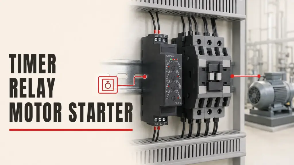
کونٹیکٹر بار بار آپریشنل سوئچنگ انجام دیتا ہے اور جب کوئی حفاظتی ریلے کام کرتا ہے تو کنٹرول سرکٹ کو موٹر روکنے کی اجازت دیتا ہے۔ اس کی یوٹیلائزیشن کیٹیگری، آپریشنل کرنٹ، کوائل/کنٹرول وولٹیج، سوئچنگ فریکوئنسی، اور حفاظتی آلات کے ساتھ کوآرڈینیشن کا اطلاق کے مطابق ہونا ضروری ہے۔.
ایک کونٹیکٹر خود سے اوورلوڈ کا پتہ نہیں لگاتا اور اس کا مقصد کسی بھی شارٹ سرکٹ کرنٹ کو منقطع کرنا نہیں ہے۔ جب اسے مطلوبہ کنٹرول اور حفاظتی افعال کے ساتھ ملایا جاتا ہے تو یہ موٹر سٹارٹر کا حصہ بن جاتا ہے۔ ملاحظہ کریں کنٹیکٹر بمقابلہ موٹر اسٹارٹر اور وی او ایکس (VIOX) AC کونٹیکٹر رینج.
اوورلوڈ ریلے
ایک اوورلوڈ ریلے موٹر کے کرنٹ کو براہ راست یا بالواسطہ طور پر ماپتا ہے اور جب اس کی ٹائم-کرنٹ یا تھرمل-ماڈل کی حد سے تجاوز ہو جائے تو کونٹیکٹر کو کھلنے کا حکم دیتا ہے۔ تھرمل اور الیکٹرانک ڈیزائن ایڈجسٹمنٹ رینج، فیز-فیلر رویے، درجہ حرارت کے معاوضے، ری سیٹ کے اختیارات، ٹرپ کلاس، تشخیص، اور اضافی افعال میں مختلف ہوتے ہیں۔.
ٹرپ کلاس کو موٹر کے تھرمل برداشت سے تجاوز کرنے سے پہلے کام کرتے ہوئے موٹر کو جائز طریقے سے سٹارٹ ہونے کی اجازت دینی چاہیے۔ صرف پریشان کن ٹرپنگ کو روکنے کے لیے سست کلاس کا انتخاب کرنے سے رکی ہوئی یا اوورلوڈ موٹر ناکافی طور پر محفوظ رہ سکتی ہے۔ VIOX تھرمل اوورلوڈ ریلے گائیڈ ڈیوائس کی وضاحت کرتی ہے، جبکہ تھرمل اوورلوڈ ریلے بمقابلہ MPCB ان کی حفاظتی حدود کی وضاحت کرتی ہے۔.
تھری-فیز مانیٹرنگ ریلے
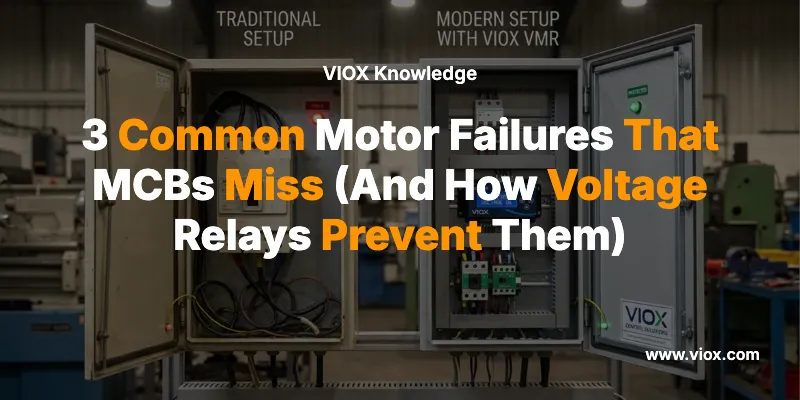
ایک وولٹیج مانیٹرنگ ریلے اسٹارٹ کی اجازت دینے سے پہلے یا موٹر کے چلنے کے دوران فیز سیکونس، فیز کے ضائع ہونے، وولٹیج کے عدم توازن، انڈر وولٹیج، اور اوور وولٹیج کی نگرانی کر سکتا ہے۔ یہ تب مفید ہوتا ہے جب سپلائی کا معیار ایک قابلِ ذکر خطرہ ہو، خاص طور پر جہاں غلط فیز سیکونس مشینری کو الٹا چلا سکتا ہے۔.
تاہم، وولٹیج کی نگرانی اور کرنٹ کی نگرانی ایک دوسرے کے متبادل نہیں ہیں۔ وولٹیج سینسنگ پوائنٹ کے بعد کوئی کھلا کنڈکٹر یا ناکام کونٹیکٹ کرنٹ کے ضائع ہونے کی ایسی حالت پیدا کر سکتا ہے جسے ریلے نہیں دیکھ پاتا۔ اس کے برعکس، کرنٹ کے لیے حساس اوورلوڈ ریلے فیز ریورسل کے بعد اسٹارٹ اپ کو لازمی طور پر نہیں روکتا۔ ان کے سینسنگ کے مقامات اور پیمائش کیے گئے متغیرات کو پروٹیکشن ڈایاگرام پر دکھایا جانا چاہیے۔.
ایمبیڈڈ ٹمپریچر سینسرز
ایمبیڈڈ PTC تھرمسٹرز یا RTDs اپنے نصب شدہ مقامات کے قریب درجہ حرارت کا مشاہدہ کرتے ہیں۔ یہ خاص طور پر وہاں قیمتی ہوتے ہیں جہاں موٹر کرنٹ قابلِ اعتماد طریقے سے ہیٹنگ کی پیش گوئی نہیں کرتا، بشمول خراب کولنگ، غیر معمولی محیطی درجہ حرارت، بار بار اسٹارٹ ہونا، کم رفتار پر آپریشن، یا انورٹر سے چلنے والے مخصوص فرائض۔.
IEC 60034-11:2020 اپنے بیان کردہ موٹر اسکوپ کے اندر شامل تھرمل پروٹیکٹرز اور ڈیٹیکٹرز کے لیے تقاضوں کی وضاحت کرتا ہے۔ سینسر، ایویلیوایٹر، ٹرپ سرکٹ، ری سیٹ لاجک، اور فیلیر رسپانس کو ایک الگ تھلگ لوازمات کے بجائے ایک مکمل پروٹیکشن چین کے طور پر سمجھا جانا چاہیے۔.
تین عملی حفاظتی آرکیٹیکچرز
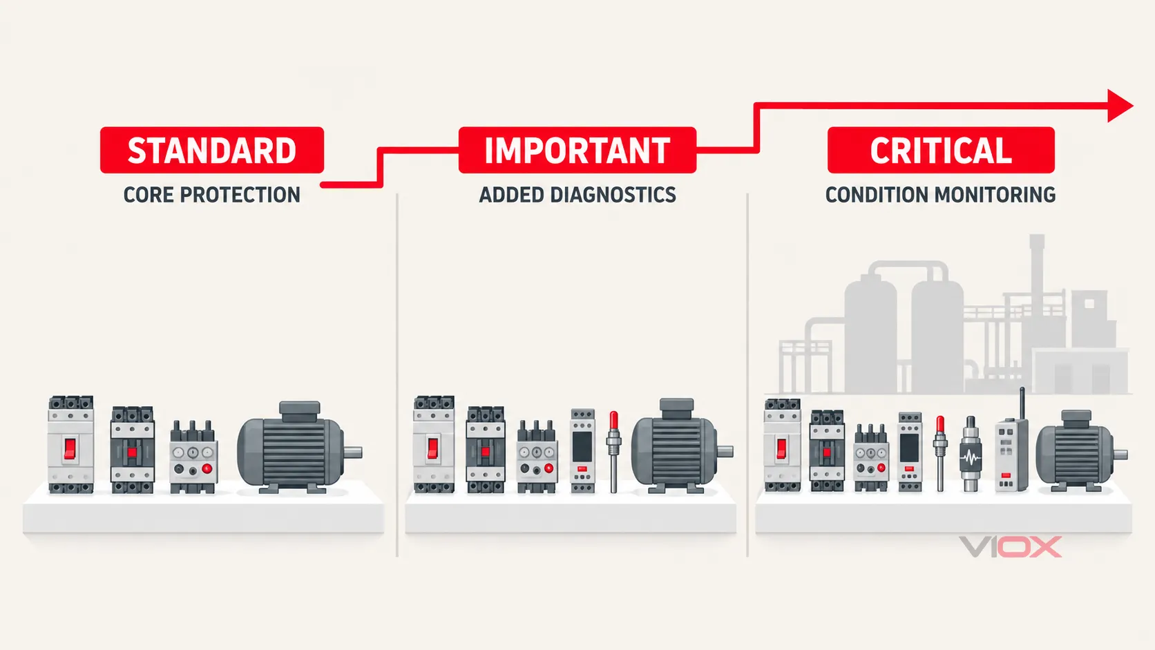
پروٹیکشن کی گہرائی نتائج اور قابلِ شناخت فیلیر موڈز پر منحصر ہوتی ہے، نہ کہ صرف موٹر کے سائز پر۔ ڈیوائس گروپس تصوراتی ہیں اور انہیں اصل پروجیکٹ کے لیے تصدیق شدہ ہونا چاہیے۔.
ٹیئر 1: معیاری موٹر سرکٹ
ایک عام معیاری ڈیوٹی آرکیٹیکچر میں درج ذیل شامل ہوتے ہیں:
- برانچ شارٹ سرکٹ پروٹیکشن؛;
- ایک کونٹیکٹر یا مناسب سٹارٹر؛;
- موٹر اوورلوڈ پروٹیکشن؛;
- منتخب کردہ ڈیوائس کے امتزاج کے لیے تصدیق شدہ شارٹ سرکٹ کوآرڈینیشن؛;
- ایک کنٹرول سرکٹ جو ضرورت پڑنے پر غیر محفوظ خودکار ری اسٹارٹ کو روکتا ہے۔.
اسے فیوز یا بریکر کے ساتھ کونٹیکٹر اور اوورلوڈ ریلے، یا MPCB کے ساتھ کونٹیکٹر کے طور پر لاگو کیا جا سکتا ہے۔ اس کا انتخاب ایک اسمبلی کا فیصلہ ہے، نہ کہ انفرادی آلات کے درمیان مقابلہ۔ دونوں انتظامات کا موازنہ کریں MCB + Contactor + Overload Relay بمقابلہ MPCB + Contactor.
ٹیئر 2: اہم موٹر سرکٹ
پیداوار کے لیے اہم یا مکینیکل طور پر زیادہ بوجھ والے لوڈز کے لیے، خطرے کے جائزے سے ثابت شدہ افعال شامل کریں:
- فیز کے ضائع ہونے اور کرنٹ کے عدم توازن کی نشاندہی؛;
- طویل اسٹارٹ یا اسٹال سے تحفظ؛;
- سپلائی وولٹیج اور فیز سیکونس کی نگرانی؛;
- دستیاب ہونے پر PTC یا RTD وائنڈنگ-ٹمپریچر ان پٹ؛;
- لوڈ ختم ہونے کی صورتحال کے لیے انڈر کرنٹ یا انڈر پاور سے تحفظ؛;
- ٹرپ ہونے کی وجہ کی نشاندہی اور ایونٹ ہسٹری؛;
- الارم آؤٹ پٹس جو محفوظ ہونے کی صورت میں شٹ ڈاؤن سے پہلے مداخلت کی اجازت دیتے ہیں۔.
مقصد ہر ریلے کو انسٹال کرنا نہیں ہے۔ بلکہ ان قابلِ یقین فیلیر موڈز کا احاطہ کرنا ہے جنہیں بنیادی اوور کرنٹ اور اوورلوڈ فنکشنز شناخت نہیں کر سکتے۔.
ٹائر 3: اہم موٹر سرکٹ
اہم موٹرز کے لیے ملٹی فنکشن موٹر مینجمنٹ ریلے یا پروٹیکشن ریلے کے ساتھ براہ راست کنڈیشن سینسنگ کا استعمال درست ہو سکتا ہے۔ مشین اور عمل کے لحاظ سے، آرکیٹیکچر میں درج ذیل شامل ہو سکتے ہیں:
- کرنٹ، وولٹیج، تھرمل ماڈل، سٹال، اور سٹارٹ کی نگرانی؛;
- وائنڈنگ اور بیئرنگ کے درجہ حرارت کے چینلز؛;
- وائبریشن یا مکینیکل کنڈیشن کی مانیٹرنگ؛;
- سٹارٹ-کاؤنٹ اور ری سٹارٹ-انہبٹ لاجک؛;
- PLC، DCS، یا اثاثہ جات کے انتظام کے نظام کے ساتھ مواصلت؛;
- پری ٹرپ الارم، ایونٹ ریکارڈز، اور ٹائم اسٹیمپڈ فالٹ ڈیٹا؛;
- کنٹرول پاور کی ناکامی سے تحفظ اور ایک انجینئرڈ ری اسٹارٹ فلاسفی؛;
- ریڈنڈنسی (تکرار) جہاں ایک سنگل سینسر یا ٹرپ سرکٹ ناقابل قبول خطرہ پیدا کر سکتا ہو۔.
اہمیت کا مطلب خود بخود زیادہ سے زیادہ پیچیدگی نہیں ہے۔ ہر اضافی سینسر، ٹرپ پاتھ، اور مواصلاتی انحصار ٹیسٹنگ اور دیکھ بھال کی ذمہ داریاں بڑھاتا ہے۔ ڈیزائن کو ممکنہ حد تک سادہ ہونا چاہیے جبکہ یہ متعین خطرات کا احاطہ بھی کرے۔.
اسٹارٹنگ کا طریقہ حفاظتی مسئلے کو تبدیل کر دیتا ہے
ڈائریکٹ آن لائن سٹارٹنگ
Direct-on-line (DOL) اسٹارٹنگ ایک ہائی اسٹارٹنگ کرنٹ اور ایک متعین ایکسیلریشن پیریڈ پیدا کرتی ہے۔ اوورلوڈ کی خصوصیت کو نارمل اسٹارٹ کے دوران برقرار رہنا چاہیے لیکن ناکام اسٹارٹ یا لاکڈ روٹر کے موٹر کی تھرمل صلاحیت سے تجاوز کرنے سے پہلے عمل کرنا چاہیے۔ لہذا ایکسیلریشن کے دوران دستیاب وولٹیج اور ڈرائیون لوڈ کا انرشیا صرف کارکردگی کی تفصیلات نہیں بلکہ پروٹیکشن ان پٹس ہیں۔.
اسٹار-ڈیلٹا اسٹارٹنگ
اسٹار-ڈیلٹا سسٹمز میں کونٹیکٹرز، ٹرانزیشن ٹائمنگ، اور اوورلوڈ ریلے کے متعدد ممکنہ مقامات کا اضافہ ہوتا ہے۔ اوورلوڈ ایلیمنٹ کے ذریعے دیکھا جانے والا کرنٹ اس بات پر منحصر ہے کہ آیا اسے لائن میں نصب کیا گیا ہے یا ڈیلٹا سرکٹ کے اندر۔ اسٹارٹر بنانے والے کی دستاویزی ترتیب اور سیٹنگ کے طریقہ کار کا استعمال کریں؛ لائن سے منسلک سیٹنگ کے اصول کو انسائیڈ-ڈیلٹا انسٹالیشن پر منتقل نہ کریں۔.
سافٹ اسٹارٹر سے چلنے والی موٹرز
ایک سافٹ اسٹارٹر ایکسلریشن کے دوران وولٹیج کو کنٹرول کرتا ہے اور اس میں اوورلوڈ، اسٹال، فیز، بائی پاس، اور تھرمل ماڈل کے فنکشنز شامل ہو سکتے ہیں۔ شامل خصوصیات ماڈل کے لحاظ سے مختلف ہوتی ہیں۔ اپ اسٹریم شارٹ سرکٹ پروٹیکٹو ڈیوائس، بائی پاس کا انتظام، اوورلوڈ کی ذمہ داری، موٹر سینسر ان پٹ، اور مطلوبہ کوآرڈینیشن کا تعین اب بھی کیا جانا ضروری ہے۔ مینو میں موجود کسی فیچر کا نام اس بات کا ثبوت نہیں ہے کہ مکمل برانچ سرکٹ محفوظ ہے۔.
ویری ایبل فریکوئنسی ڈرائیو سے چلنے والی موٹرز
ایک ویری ایبل فریکوئنسی ڈرائیو (VFD) سسٹم کی حدود کو تبدیل کرتی ہے۔ لائن سائیڈ، ڈرائیو پاور الیکٹرانکس، آؤٹ پٹ کیبل، اور موٹر، ہر ایک کے تحفظ کے خدشات مختلف ہیں۔ ڈرائیو کے اندر موجود فنکشنز آؤٹ پٹ کرنٹ اور موٹر کے تھرمل ماڈلز کی نگرانی کر سکتے ہیں، لیکن وہ خود بخود ہر مطلوبہ اپ اسٹریم پروٹیکٹو ڈیوائس یا براہ راست موٹر ٹمپریچر سینسر کی جگہ نہیں لیتے۔.
کم رفتار کولنگ، ریفلیکٹڈ ویو اسٹریس، کیبل کی لمبائی، سوئچنگ فریکوئنسی، بیئرنگ کرنٹ، ہارمونکس، اور ری اسٹارٹ کا رویہ متعلقہ ہو سکتے ہیں۔ ڈرائیو اور موٹر بنانے والوں کی مربوط ہدایات پر عمل کریں۔ کنٹرول کے فیصلے کے لیے، دیکھیں VFD بمقابلہ سافٹ اسٹارٹر.
کوآرڈینیشن اور سیٹنگ ورک فلو
پروٹیکشن میٹرکس کو ایک دستاویزی ڈیزائن میں تبدیل کرنے کے لیے درج ذیل ترتیب کا استعمال کریں۔.
1. قابلِ یقین فالٹس اور مطلوبہ ردعمل کی وضاحت کریں
ہر موٹر کے لیے، غیر معمولی حالت کی نشاندہی کریں، یہ کہ اسے کیا چیز ڈیٹیکٹ کر سکتی ہے، آیا مطلوبہ ردعمل الارم، بلاکڈ اسٹارٹ، کنٹرولڈ اسٹاپ، فوری ٹرپ، یا مینٹیننس نوٹیفکیشن ہے، اور آیا خودکار ری اسٹارٹ کی اجازت ہے یا نہیں۔.
2. سینسنگ اور انٹرپشن کی حدود کھینچیں
نشان زد کریں کہ وولٹیج، فیز کرنٹ، بقایا کرنٹ، اور درجہ حرارت کہاں ماپا جاتا ہے۔ پھر نشاندہی کریں کہ کون سا آلہ پاور سرکٹ کو کھولتا ہے۔ یہ ڈیزائن کی ایک عام غلطی کو روکتا ہے: ریلے فنکشن کی وضاحت کرنا اس بات کی تصدیق کیے بغیر کہ اس کا ٹرپ آؤٹ پٹ موٹر کو محفوظ طریقے سے منقطع کر سکتا ہے۔.
3. شارٹ سرکٹ سے بچاؤ کے آلے کا انتخاب کریں
دستیاب فالٹ کرنٹ کا حساب لگائیں یا حاصل کریں۔ مکمل سٹارٹر کمبی نیشن کے لیے انٹرپٹنگ کیپیسٹی اور مینوفیکچرر کے کوآرڈینیشن ڈیٹا کی تصدیق کریں۔ کنڈکٹر کے تحفظ اور کسی بھی درکار بیک اپ حفاظتی آلے کو چیک کریں۔.
4. اوورلوڈ فنکشن کا انتخاب کریں
موٹر نیم پلیٹ ڈیٹا، ڈیوٹی، ایکسلریشن ٹائم، قابل اجازت سٹارٹس، محیطی حالات، اور موٹر کی تھرمل معلومات کا استعمال کریں۔ ایڈجسٹمنٹ رینج اور ٹرپ کی خصوصیت کا انتخاب کریں تاکہ ایک درست سٹارٹ کی اجازت ہو جبکہ مسلسل اوورلوڈ، سٹال، یا طویل ایکسلریشن کو موٹر کی حد کے اندر حل کیا جا سکے۔.
5. وہ فنکشنز شامل کریں جو بنیادی کرنٹ پروٹیکشن فراہم نہیں کر سکتی
یہ فیصلہ کرنے کے لیے فالٹ میٹرکس کا استعمال کریں کہ آیا وولٹیج مانیٹرنگ، براہ راست درجہ حرارت کی سینسنگ، انڈرلوڈ پروٹیکشن، بیئرنگ کا درجہ حرارت، وائبریشن، یا پروسیس انسٹرومینٹیشن کی ضرورت ہے۔ ریکارڈ کریں کہ ہر فنکشن کیوں موجود ہے اور آپریشن کے دوران یہ کیا کرتا ہے۔.
6. سلیکٹیوٹی اور کوآرڈینیشن کی تصدیق کریں
موٹر پروٹیکٹر، برانچ پروٹیکٹو ڈیوائس، فیڈر پروٹیکشن، کونٹیکٹر، اوورلوڈ ریلے، اور کنٹرول لاجک کے مابین تعامل کو چیک کریں۔ جہاں سلیکٹیو آپریشن درکار ہو اور سسٹم ڈیزائن اس کی معاونت کرتا ہو، وہاں ڈاؤن اسٹریم موٹر فالٹ کی وجہ سے غیر متعلقہ لوڈز کو غیر ضروری طور پر منقطع نہیں ہونا چاہیے۔.
7. مکمل پروٹیکشن چین کو کمیشن کریں
کمیشننگ کے دوران منظور شدہ طریقوں اور مینوفیکچرر کی ہدایات کے ساتھ درج ذیل کی تصدیق ہونی چاہیے:
- ڈیوائس کی شناخت، ریٹنگ، سیٹنگز، اور دستاویزی کوآرڈینیشن کا امتزاج؛;
- کرنٹ ٹرانسفارمر کا تناسب اور پولرٹی جہاں لاگو ہو؛;
- سینسر کی تسلسل (continuity) اور کنفیگر شدہ سینسر کی قسم؛;
- فیز سیکونس اور مانیٹرڈ وولٹیج کی حدود؛;
- ٹرپ آؤٹ پٹ، کونٹیکٹر یا بریکر کا آپریشن، اور انڈیکیشن؛;
- الارم بمقابلہ ٹرپ لاجک؛;
- ری سیٹ موڈ اور ری اسٹارٹ انہیبیٹ؛;
- کمیونیکیشن، ایونٹ ریکارڈنگ، اور کنٹرول پاور کے ضائع ہونے پر رویہ؛;
- ڈرائنگز، لیبلز، سیٹنگز، اور پروٹیکشن شیڈول کے درمیان مطابقت۔.
کسی بھی عارضی فنکشنل ٹیسٹ کے طور پر شارٹ سرکٹ پیدا نہ کریں، موٹر کو اسٹال نہ کریں، یا وائنڈنگ کو زیادہ گرم نہ کریں۔ مینوفیکچرر کے منظور شدہ سیکنڈری انجیکشن، ٹیسٹ موڈز، سیمولیشن انٹرفیس، یا نصب شدہ آلات کے لیے موزوں کنٹرولڈ کمیشننگ کے طریقہ کار کا استعمال کریں۔.
موٹر پروٹیکشن شیڈول چیک لسٹ
کوٹیشن یا ڈیزائن شیڈول کے لیے ایک مفید درخواست میں موٹر پاور سے زیادہ معلومات ہونی چاہئیں:
| معلومات کا گروپ | مطلوبہ پروجیکٹ ڈیٹا |
|---|---|
| سپلائی | وولٹیج، فریکوئنسی، فیزز، گراؤنڈنگ کا انتظام، دستیاب فالٹ کرنٹ |
| موٹر | پاور، ریٹیڈ کرنٹ، اسپیڈ، کارکردگی، سروس فیکٹر جہاں لاگو ہو، انسولیشن/درجہ حرارت کا ڈیٹا |
| اسٹارٹنگ | DOL، اسٹار-ڈیلٹا، سافٹ اسٹارٹر، یا VFD؛ اسٹارٹنگ کرنٹ؛ ایکسلریشن کا وقت؛ فی گھنٹہ اسٹارٹس |
| لوڈ | پمپ، پنکھا، کنویئر، کمپریسر، ہوسٹ، کرشر، یا دیگر؛ انرشیا؛ ممکنہ جام/انڈرلوڈ کی حالت |
| ماحولیات | محیط درجہ حرارت، اونچائی، انکلوژر، دھول، نمی، زنگ، خطرناک علاقے کی درجہ بندی اگر لاگو ہو |
| سینسر | PTC، RTD، تھرموسٹیٹ، بیئرنگ سینسرز، وائبریشن، پروسیس سوئچز |
| تحفظ | مطلوبہ فالٹ فنکشنز، الارم/ٹرپ ایکشن، ری اسٹارٹ پالیسی، کوآرڈینیشن لیول، کمیونیکیشن |
| دستاویزی | ون لائن ڈایاگرام، کنٹرول اسکیمیٹک، سیٹنگز شیٹ، کوآرڈینیشن ٹیبلز، کمیشننگ ریکارڈز |
VIOX موٹر کنٹرول سلوشن کی درخواست کرتے وقت، صرف موٹر کے kW یا ہارس پاور کے بجائے یہ شیڈول فراہم کریں۔ VIOX پھر مناسب شناخت میں مدد کر سکتا ہے ایم پی سی بی, اوورلوڈ ریلے, AC کنٹیکٹر, ، اور متعلقہ مانیٹرنگ آرکیٹیکچر۔ پروجیکٹ کے مطابق تصدیق کی ذمہ داری کوالیفائیڈ سسٹم ڈیزائنر پر عائد ہوتی ہے۔.
حتمی ڈیزائن کا اصول
صحیح سوال یہ نہیں ہے کہ “کون سا سرکٹ بریکر اس موٹر کو محفوظ رکھتا ہے؟” بلکہ یہ ہے:
کون سے قابلِ یقین فیلیر موڈز اس موٹر یا عمل کو نقصان پہنچا سکتے ہیں، کون سا متغیر ہر ایک کو ظاہر کرتا ہے، اور کون سا کوآرڈینیٹڈ ڈیوائس وقت پر الارم دے گا یا سرکٹ کو منقطع کرے گا؟
ایک بار جب اس سوال کا جواب مل جائے، تو ڈیوائس کا انتخاب قابلِ سراغ ہو جاتا ہے۔ شارٹ سرکٹ پروٹیکشن، اوورلوڈ پروٹیکشن، سوئچنگ، سپلائی مانیٹرنگ، براہ راست درجہ حرارت کی سینسنگ، اور مکینیکل کنڈیشن مانیٹرنگ کو اس دعوے کے بغیر تفویض کیا جا سکتا ہے کہ کوئی ایک جزو موٹر کو مکمل تحفظ فراہم کرتا ہے۔.
ذرائع اور معیارات
- IEEE 3004.8-2016، صنعتی اور کمرشل پاور سسٹمز میں موٹر پروٹیکشن کے لیے تجویز کردہ پریکٹس
- IEC 60947-4-1:2023، کونٹیکٹرز اور موٹر اسٹارٹرز، درست شدہ ورژن 2026-03
- IEC 60034-11:2020، گھومنے والی برقی مشینیں - تھرمل پروٹیکشن
- IEC 60034-26:2026، تھری فیز کیج انڈکشن موٹرز پر غیر متوازن وولٹیجز کے اثرات
VIOX ایڈیٹوریل ٹیم کی تحریر۔ آخری بار 19 ستمبر 2026 کو اپ ڈیٹ کیا گیا۔.