Bu sayfada
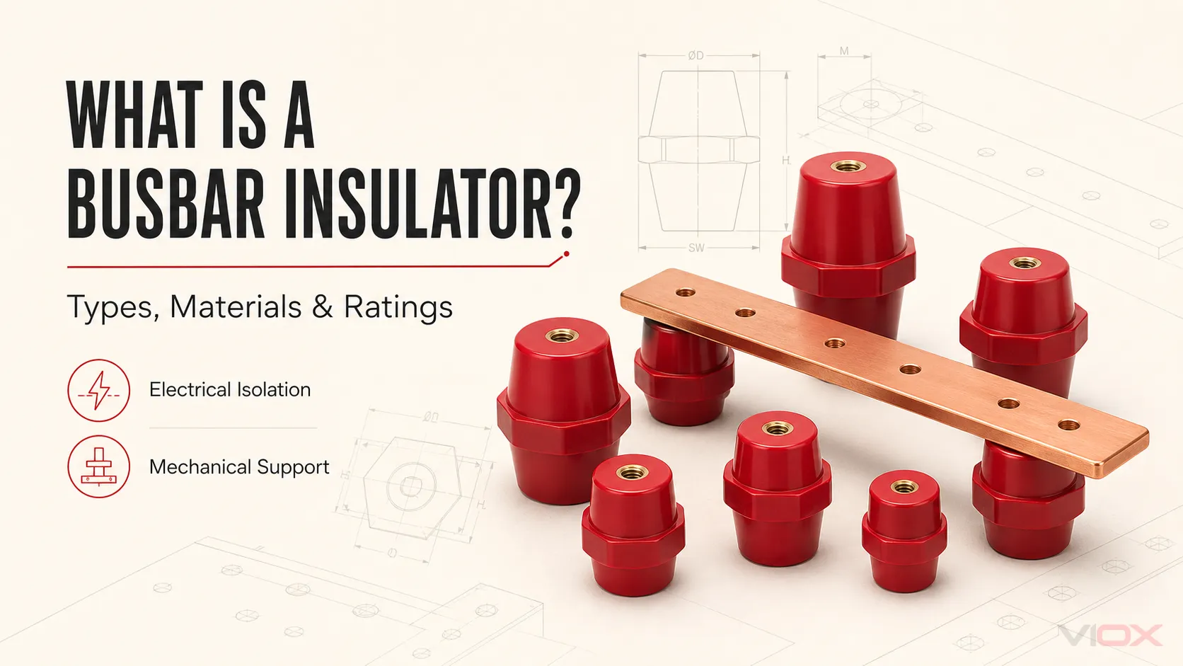
A bara izolatörü canlı bir bakır veya alüminyum bara sistemini, topraklanmış metal aksamdan, panodan ve bitişik iletkenlerden elektriksel olarak ayırırken aynı zamanda konumunda tutan iletken olmayan bir destektir. elektriksel yalıtım ve mekanik destek şalt cihazları, dağıtım panoları, kontrol panelleri, invertör kabinleri ve diğer güç tertibatlarının içinde.
Bir bara izolatörü, fiziksel ayırmadan daha fazlasını yapmalıdır. Yalıtım ve yüzeysel kaçak mesafelerini korumaya yardımcı olur, baranın mekanik yükünü taşır, faz aralığını muhafaza eder ve nakliye, titreşim, termal döngü ve kısa devre olaylarının neden olduğu kuvvetlere karşı direnç gösterir.
| Kısa bir soru | Mühendislik cevabı |
|---|---|
| Ne işe yarar? | Bir barayı destekler ve onu topraklanmış veya canlı iletken parçalardan izole eder |
| Yaygın tipleri nelerdir? | Standoff, direk, destek bloğu, tutucu, kelepçe ve özel kalıplanmış destek |
| Hangi malzemeler kullanılır? | BMC/DMC, SMC, epoksi reçine, porselen ve mühendislik kompozitleri |
| Seçimi ne belirler? | Gerilim, yüzeysel kaçak yolu, açıklık, bara geometrisi, destek aralığı, kısa devre kuvvetleri, montaj donanımı ve ortam |
| Sadece gerilim yeterli midir? | Hayır. İzolatör, komple bara düzeneğinin bir parçası olarak değerlendirilmelidir |
Mevcut boyutlar ve yapı seçenekleri için şuraya bakınız: VIOX bara izolatörü ürün yelpazesi. Bu makale bileşeni ve mühendislik sınırlarını açıklamaktadır; ayrı olan bölüm ise tam spesifikasyon sürecini kapsamaktadır. bara yalıtkanı seçim kılavuzu Busbar izolatörü iki bağlantılı işlevi yerine getirir:.
Önemli Çıkarımlar
- Yaygın busbar izolatörleri arasında dişli mesnetler, post izolatörler, destek blokları ve kelepçe tipi destekler bulunur. elektriksel yalıtım ve yapısal destektir.
- Ürünün yüksekliği veya rengi, voltaj kapasitesini, malzeme performansını veya mekanik dayanımını belirlemez.
- Açıklık ve yüzeysel kaçak mesafesi, sadece izolatör gövdesi tarafından oluşturulan değerler değil, kurulu geometrinin özellikleridir.
- Kısa devre dayanımı, komple busbar ve montaj tasarımına aittir. Münferit bir destek derecesi, tek başına bir montaj derecesini kanıtlamaz.
- Satın alınan modeli her zaman teknik çizimi, malzeme dokümantasyonu, diş düzeni ve modele özgü elektriksel ve mekanik verileri ile eşleştirin.
- Always match the purchased model to its drawing, material documentation, thread arrangement, and model-specific electrical and mechanical data.
Bara İzolatörü Ne İşe Yarar?
Baralar, sert bakır veya alüminyum iletkenler kullanarak bir pano içerisindeki akımı dağıtır. Bu iletkenler, toprağa veya başka bir faza istenmeyen bir yol oluşturmadan güvenli bir şekilde monte edilmelidir. Bara destek izolatörü, enerjili iletken ile destek yapısı arasında mekanik bir arayüz sağlar.
1. Elektriksel İzolasyon Sağlar
Yalıtkan gövde, enerjili barayı aşağıdaki gibi iletken parçalardan ayırır:
- pano gövdesi ve montaj plakası
- yapısal çerçeveler ve raylar
- bitişik faz baraları
- kablo pabuçları ve terminaller
- topraklanmış bariyerler
- yakındaki kontrol veya koruma ekipmanı
Elektriksel ayrım, yalnızca kalıplama bileşiğinin dielektrik dayanımına değil, birkaç değişkene bağlıdır:
- Gümrükleme iki iletken parça arasındaki hava yoluyla olan en kısa mesafedir.
- Yüzey kaçak yolu bir yalıtım malzemesinin yüzeyi boyunca olan en kısa mesafedir.
- Kirlilik derecesi beklenen kirlenmeyi ve bunun iletken hale gelip gelemeyeceğini tanımlar.
- Malzeme grubu genellikle Karşılaştırmalı İzleme İndeksi (CTI) ile bağlantılı olan izleme davranışını yansıtır.
- Aşırı gerilim kategorisi ve sistem gerilimi Beklenen elektriksel gerilimi tanımlayın.
- Yükseklik hava aralığı gereksinimini etkileyebilir.
Mevcut birleştirilmiş sürüm, IEC 60664-1:2020+AMD1:2025 CSV, belirtilen kapsam dahilinde AC 1.000 V veya DC 1.500 V'a kadar alçak gerilim besleme sistemlerine bağlı ekipmanlar için yalıtım koordinasyonu prensiplerini sağlar. Bara yalıtım tasarımı, “kV başına 1 mm” gibi evrensel bir kurala indirgenemez. Gerekli geometri, gerçek sistem ve ortam için belirlenmelidir.
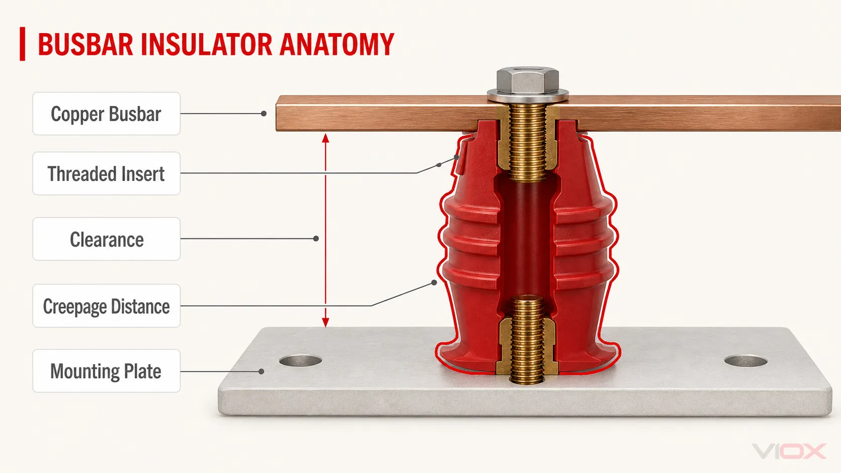
2. Mekanik Destek Sağlar
Aynı parça barayı taşımalı ve konumunu korumalıdır. Mekanik görevi şunları içerebilir:
- iletkenin ve bağlı donanımın kütlesi
- kablo bağlantıları ve bükümlerinin oluşturduğu kuvvetler
- çalışma sırasındaki titreşim
- taşıma veya montaj sırasındaki şok
- tekrarlanan termal genleşme ve büzülme
- kısa devre sırasındaki elektrodinamik kuvvetler
Benzer iletken geometrisi için, tepe mekanik kuvvet tepe kısa devre akımı ile hızla artar:
Tepe elektrodinamik kuvvet ∝ iₚ²Tepe mekanik kuvvet esas olarak tepe kısa devre akımına, iletken geometrisine, iletken aralığına, destek açıklığına ve yükün destek yapısına nasıl aktarıldığına bağlıdır. Arıza süresi, ilgili termal gerilmeyi ve mekanik şok ile titreşimin tertibat üzerinde etki ettiği süreyi etkiler.
Bu nedenle, münferit bir bara destek izolatörü, bir şalt panosunun kısa devre dayanım değerinin tek kanıtı olarak asla kullanılmamalıdır.
3. Tasarlanan Bara Geometrisini Korur
Tutarlı bir destek sistemi, fazları hizalı tutar ve üretim ile servis süresince hedeflenen mesafeleri korur. Bu durum, küçük bir iletken yer değiştirmesinin açıklığı azaltabileceği, bir bağlantıya dengesiz yük bindirebileceği veya canlı bir parçayı topraklanmış metal aksama yaklaştırabileceği kompakt panolarda özellikle önemlidir.
Bir orijinal ekipman üreticisi (OEM) için tekrarlanabilir geometri, montaj tutarlılığını da artırır. Bir destek düzeni, yalnızca elle ayarlanmış bir prototipte değil, tüm üretim birimlerinde aynı şekilde çalışmalıdır.
Bara İzolatörü, Destek İzolatörü ve Standoff (Ayırıcı): Fark Nedir?
Piyasada birbiriyle örtüşen çeşitli isimler kullanılmaktadır. Doğru terim, bileşenin geometrisine ve işlevine bağlıdır.
| Dönem | Pratik anlam | Tipik uygulama |
|---|---|---|
| Bara izolatörü | Bir barayı destekleyen ve ayıran yalıtkan parça için kullanılan genel terim | Şalt cihazları, dağıtım panoları, pano sistemleri, kontrol panelleri |
| Bara destek izolatörü | Yapısal destek işlevini vurgular | Ana ve dağıtım bara hatları |
| İzolatör mesnet | Bir iletkeni montaj yüzeyinin üzerine yükselten dişli ara parça tipi destek | Alçak gerilim panoları, evirici (inverter) kabinleri, DC montaj grupları |
| Mesnet izolatörü | Genellikle nervürlü veya kademeli bir profile sahip daha yüksek destek | Daha fazla yükseklik, yüzey yolu veya tanımlanmış mekanik destek gerektiren uygulamalar |
| Bara tutucu veya destek bloğu | Bir veya daha fazla barayı sabit aralıklarla konumlandıran kalıplanmış parça | Modüler ve seri üretim bara montaj grupları |
| Geçit izolatörü (Bushing) | Bir iletkenin iletken bir bariyer boyunca geçmesini sağlayan içi boş yalıtım | Muhafaza, transformatör veya şalt sahası geçişi |
Bu nedenle bir destek izolatörü, bir bara izolatörü türüdür. Bir buşing (bushing) ise değildir: alttan destekleme sorunundan ziyade bir iletken geçişi sorununu çözer.
Bir MCCB, kalıplanmış yalıtım muhafazası içine alınmış bir aşırı akım koruma cihazıdır. Devrenin tipik olarak minyatür bir branşman kesicinin sunabileceğinden daha sağlam bir koruma talep ettiği alçak gerilim sistemleri için tasarlanmıştır. bara izolatörü bazı aramalarda karşımıza çıkar, ancak potansiyel olarak belirsizdir çünkü izolatör normalde ayırıcı veya izolasyon şalteri anlamına gelir. Destek bileşenleri için, bara izolatörü veya bara destek izolatörü daha net bir mühendislik İngilizcesidir.
Ana Bara İzolatörü Türleri ve Uygulamaları
Bara izolatörü türleri, yalnızca renk veya gerilime göre değil, montaj şekli ve destek işlevine göre sınıflandırıldığında daha doğru olur.
| Tip | İnşaat | En uygun kullanım alanı | Ana kontroller |
|---|---|---|---|
| Dişli ara parça (standoff) | Ek parçalı veya saplamalı silindirik, altıgen, konik veya kademeli kalıplanmış gövde | Kompakt alçak gerilim panoları ve DC kabinleri | Yükseklik, gövde çapı, diş, ek parça derinliği, mekanik yük |
| Mesnet izolatörü | Uç bağlantı parçalarına sahip daha uzun gövde ve genellikle nervürlü profil | Daha yüksek açıklık veya daha yüksek yalıtım gerektiren uygulamalar | Yüzeysel kaçak yolu, açıklık, eğilme dayanımı, yalıtım sınıfı |
| Destek bloğu | Bir veya birden fazla barayı destekleyen kalıplanmış blok | Tekrarlanan faz düzenleri ve modüler sistemler | Bara boyutları, faz aralığı, sıkıştırma yöntemi |
| Kelepçe veya braket desteği | Kelepçe veya montaj braketi ile entegre yalıtkan destek | Özel iletken yönlendirmesi ve kısıtlı düzenler | Yük yönü, braket geometrisi, montaj delikleri |
| Özel kalıplanmış destek | Uygulamaya özel gövde, ek parça ve iletken arayüzü | Standart dışı geometriye sahip OEM ekipmanları | Çizim kontrolü, kalıplama, malzeme, tolerans, doğrulama |
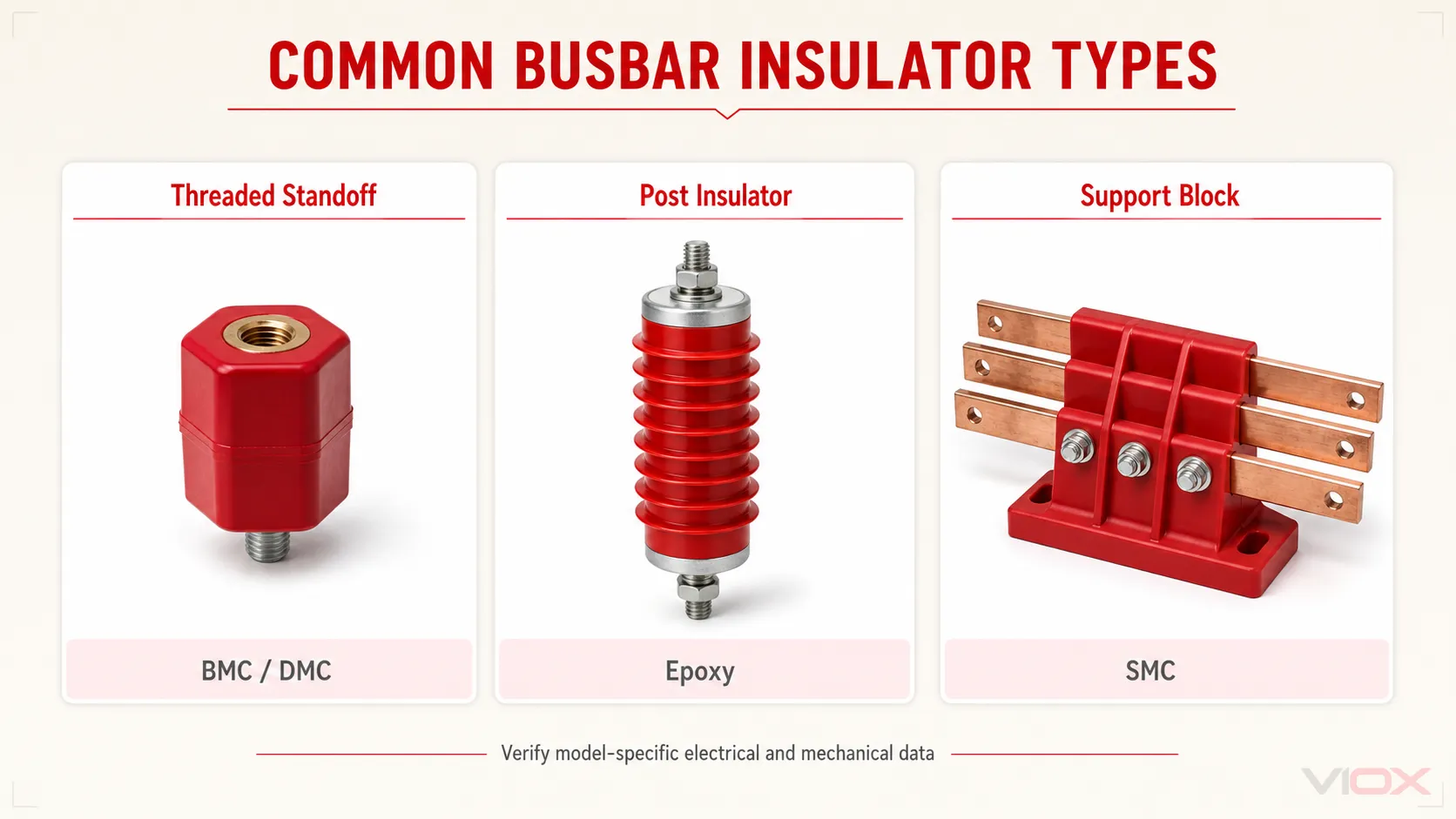
Dişli saplamalar; kompakt alçak gerilim panoları, invertör kabinleri, DC dağıtım ekipmanları, BESS kabinleri ve EV şarj ekipmanlarında en yaygın kullanılan formdur. Arayüzleri dişi-dişi, erkek-dişi veya erkek-erkek olabilir.
İzolatör mesnetleri genellikle daha uzundur ve yüzey yolunu artırmak için kanatçıklar veya kademeler kullanabilir. Destek blokları ise bir veya daha fazla bara çubuğunu sabit aralıklarla konumlandırarak üretim tekrarlanabilirliğini iyileştirebilir. Bu formlar; bağlantı parçaları, yük yönü, iletken arayüzü ve uygulanabilir testler farklılık gösterebileceğinden otomatik olarak birbirinin yerine kullanılamazlar.
Bara İzolatör Malzemelerinin Karşılaştırılması
Hiçbir bara izolatör malzemesi her uygulama için en iyisi değildir. Malzeme seçimi; yalıtım, iz oluşumu (tracking), ısı, nem, mekanik yük, üretim geometrisi ve çalışma ortamını dikkate almalıdır.
| Malzeme ailesi | Mühendislik avantajları | Önemli kısıtlamalar | Yaygın uygulama alanları |
|---|---|---|---|
| BMC/DMC termoset kompozit | Şekillendirilebilir, rijit ve kompakt yalıtım destekleri için yaygın olarak kullanılır | Performans; formülasyona, takviyeye ve proses kontrolüne bağlıdır | Alçak gerilim izolatörleri ve standart pano destekleri |
| SMC termoset kompozit | Daha büyük kalıplanmış şekiller ve yapısal destek geometrileri için uygundur | Model seviyesindeki mekanik ve elektriksel veriler hala doğrulama gerektiriyor | Çok kutuplu destekler ve daha büyük kalıplanmış parçalar |
| Epoksi reçine | Rijit yapı ve uyarlanabilir yalıtım geometrisi | Bazı mühendislik polimerlerinden daha ağır veya daha kırılgan olabilir; formülasyon önemlidir | Direk destekleri ve mühendislik ürünü yüksek yalıtımlı uygulamalar |
| Porselen veya seramik | Güçlü dielektrik ve çevresel kararlılık | Darbe veya montaj gerilimi altında ağır ve kırılgandır | Dış mekan, eski tip ve seçili yüksek gerilim uygulamaları |
| Mühendislik polimer kompoziti | Hafif ve özel geometrilere uyarlanabilir | Sıcaklık, iz oluşumu, nem, UV ve alev davranışı kaliteye göre değişiklik gösterir | Özel ve çevreye özgü destekler |
Malzeme adı tek başına bir derecelendirme değildir. Her ikisi de BMC olarak tanımlanan iki ürün; farklı dolgu maddelerine, cam elyaf içeriğine, iz direncine, yanıcılık davranışına, su emme oranına ve mekanik dayanıma sahip olabilir.
Faydalı dokümantasyon; malzeme kalitesini, uygulanabilir durumlarda CTI veya malzeme grubunu, test edilen kalınlıktaki yanıcılık sınıflandırmasını, dielektrik ve yalıtım direnci test koşullarını, ısı ve su emme verilerini, ilgili mekanik sonuçları ve boyutsal toleransları içerir.
UL 94 sınıflandırması, tanımlanmış küçük ölçekli test koşulları altında malzeme yanıcılığını tanımlar. Bu, eksiksiz bir elektriksel, mekanik veya ürün güvenliği sertifikasyonu değildir. UL Solutions, V-0, V-1, V-2, HB ve diğer sınıflandırmaların belirli numune ve alev testi koşullarına göre atandığını açıklamaktadır.
Bara İzolatörü Veri Sayfası Nasıl Okunur
Bara izolatörlerinin yanlış seçilmesinin bir nedeni, alıcıların yalnızca yükseklik ve diş boyutunu karşılaştırmasıdır. Faydalı bir veri sayfası incelemesi; boyutsal, elektriksel, mekanik, malzeme ve dokümantasyon alanlarını birbirinden ayırır.
| Veri sayfası alanı | Size ne anlatıyor | Tek başına kanıtlamadığı şey |
|---|---|---|
| Gövde yüksekliği | Montaj arayüzleri arasında oluşturulan mesafe | Her yerleşim düzeninde nihai montaj açıklığı veya yüzeysel kaçak yolu mesafesi |
| Gövde çapı veya genişliği | Kaplama alanı ve yaklaşık yapısal geometri | Test verisi olmaksızın mekanik dayanım |
| Diş ve ek parça derinliği | Bağlantı elemanı uyumluluğu ve kavrama | Doğru tork veya çekme dayanımı |
| Dayanım gerilimi | Belirtilen test yöntemi ve süresi altındaki performans | Sürekli çalışma gerilimi veya komple montaj yalıtım değeri |
| Çekme veya konsol dayanımı | Belirtilen yükleme yönü altındaki kapasite | Her türlü montaj ve arıza koşulu altındaki dayanım |
| Tork dayanımı | Belirtilen test altında ek parçanın/gövdenin direnci | Kurulum sırasında bu torkun uygulanmasına izin verilmesi |
| CTI veya malzeme grubu | Bağıl yüzey izleme davranışı | Kirlilik ve voltaj bağlamı olmaksızın gerekli yüzeysel kaçak yolu mesafesi |
| UL 94 sınıflandırması | Test edilen malzeme/numune için yanma davranışı | Tam ürün uyumluluğu veya ark direnci |
| Çalışma sıcaklığı | Model/malzeme için belirtilen çevresel aralık | Kabul edilebilir iletken sıcaklığı veya pano sıcaklık artışı doğrulaması |
Örnek: Yayınlanmış VIOX SM Serisi Verileri
Aşağıdaki seçili değerler, aynı aile içindeki modellerin nasıl farklılık gösterebileceğini göstermektedir. Bu değerler, yayınlanmış VIOX SM Serisi bara izolatörü sayfasından alınmıştır ve şartname veya satın alma öncesinde güncel teknik resim ve veri sayfası ile doğrulanmalıdır.
| Model | Yükseklik | Konu | Beyan edilen dayanım gerilimi | Beyan edilen çekme dayanımı | Beyan edilen tork dayanımı |
|---|---|---|---|---|---|
| SM-25 | 25 mm | M6 | : 6 kV | 500 lbf / 2.22 kN | 6 ft·lbf / 8.1 N·m |
| SM-40 | 40 mm | M8 | : 12 kV | 650 lbf / 2.89 kN | 12 ft·lbf / 16.3 N·m |
| SM-60 | 60 mm | M10 | 20 kV | 1.200 lbf / 5,34 kN | 35 ft·lbf / 47.5 N·m |
| SM-76 | 76 mm | M10 | 25 kV | 1.500 lbf / 6,67 kN | 40 ft·lbf / 54.2 N·m |
Yalnızca katalog değerleri: Belirtilen halka açık ürün sayfası; tam test dalga formunu, frekansı, süreyi, koşullandırmayı veya kabul kriterlerini belirtmemektedir. Şartname öncesinde modele özel test yöntemini ve raporunu talep edin.
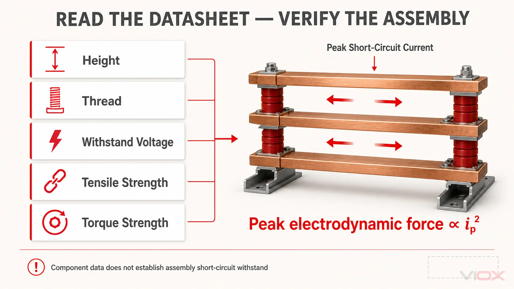
Test yöntemi, yüzeysel kaçak yolu profili, çevresel geometri, mekanik yük ve montaj gereksinimleri hala kontrol edilmelidir. Tablo ayrıca neden sadece renk ve yaklaşık yüksekliğe göre sipariş vermenin yetersiz olduğunu da göstermektedir.
Daha küçük boyutlu ara parçalar (standoff) için, yayınlanan VIOX JYZ Serisi 14 mm gövde çapı kullanır ve 14 mm ile 75 mm arasında listelenen yüksekliklere ve M4, M5 veya M6 diş seçeneklerine sahiptir. Sipariş verirken tam erkek/dişi uç düzenlemesi teyit edilmelidir.
Bara Destek İzolatörü Nasıl Seçilir
Seçim, komple bara sistemi ile başlar. Gerekli girdileri belirlemek için bu özeti kullanın, ardından hesaplama ve dokümantasyon incelemesini tamamlayın. bara yalıtkanı seçim kılavuzu.
| Seçim girdisi | Kontrol edilmesi gerekenler |
|---|---|
| Elektrik sistemi | Anma gerilimi, AC veya DC çalışma, geçici gerilim zorlanmaları, topraklama düzeni ve geçerli pano standardı |
| Kurulu yalıtım mesafeleri | Baralar, bağlantı elemanları, bariyerler, pano parçaları ve bitişik fazlar monte edildikten sonraki en kısa hava aralığı ve yüzeysel kaçak yolu mesafeleri |
| Bara geometrisi | Malzeme, genişlik, kalınlık, bara sayısı, yönelim, bükümler, birleşim yerleri ve mevcut montaj alanı |
| Mekanik görev | Bara kütlesi, titreşim, tepe kısa devre akımı, iletken aralığı, destek açıklığı ve çerçeve rijitliği |
| Montaj arayüzü | Erkek/dişi konfigürasyonu, diş, geçme derinliği, donanım, erişim ve üretici tarafından belirtilen sıkma yöntemi |
| Çevre | Sıcaklık, nem, toz, tuz, kimyasallar, yoğuşma, ultraviyole maruziyeti, irtifa ve titreşim |
| Kanıt | Akım çekişi, malzeme beyanı, modele özgü elektriksel ve mekanik veriler ve ilgili montaj doğrulaması |
Bara izolatörleri arasında evrensel bir aralık yoktur. Kısa devre dayanımının kritik olduğu durumlarda, doğrulanmış bir montaj tasarımı, geçerli yönteme dayalı bir mühendislik hesaplaması veya test kanıtı kullanın. Bir bileşenin çekme değeri, komple montajın nominal değerini belirleyemez.
Aşırı sıkma, termoset gövdeyi çatlatabilir veya geçme parçaya zarar verebilir; yetersiz sıkma ise hareketliliğe ve sürtünme korozyonuna yol açabilir. Geçme parçanın yayınlanmış tork-dayanım değeri, mutlaka önerilen montaj torku değildir.
Standartlar ve Derecelendirmeler: Bileşen ve Montaj Kapsamı
Hiçbir tekil standart, her bara izolatörünü her uygulama için sertifikalandırmaz. İlgili doküman, tasarımcının yalıtım koordinasyonunu, kalıplanmış malzemeyi, münferit bir mesnet izolatörünü veya komple panoyu değerlendirip değerlendirmediğine bağlıdır.
| Standart veya referans | Bu konuyla ilgili kapsam | Doğru yorumlama |
|---|---|---|
| IEC 60664-1:2020+AMD1:2025 CSV | Alçak gerilim kapsamındaki ekipmanlar için yalıtım koordinasyonu | Açıklık, yüzeysel kaçak yolu, kirlilik derecesi ve katı yalıtım ile ilgili kararları destekler; bir ürün kataloğu derecelendirmesi değildir |
| IEC 61439 serisi | Alçak gerilim şalt ve kontrol düzeni panoları | Kurulu bara destek sistemi dahil olmak üzere komple montaj ve doğrulaması için geçerlidir |
| IEC 60273:1990 | 1.000 V üzerindeki iç veya dış mekan AC servisleri için seramik veya cam mesnet izolatörlerinin ve 1.000 V üzerindeki iç mekan AC servisleri için organik malzemeli mesnet izolatörlerinin özellikleri | Tanımlanmış mesnet izolatörü uygulamalarıyla ilgilidir, her alçak gerilim kalıplanmış ayırıcıyı kapsamaz; standart, DC kullanımını yalnızca geçici bir referans olarak ele alır |
| UL 891 | Kuzey Amerika'daki kapalı tip (dead-front) şalt panoları | UL 891'e göre değerlendirilen bir pano içerisinde bir destek kullanıldığında geçerlidir |
| UL 508A'nın | Kuzey Amerika'daki endüstriyel kontrol panoları | Pano ve bu pano içindeki bileşenlerin kabul edilebilir kullanımı ile ilgilidir |
| UL 94 | Plastik malzemelerin yanıcılık testi | Test edilen malzeme numunelerinin yanma davranışını tanımlar, izolatörün toplam performansını değil |
IEC 61439-1:2020 Alçak gerilim şalt ve kontrol düzeni donanımları için genel kuralları belirler, ancak uygunluk, ilgili donanım bölümünün gerekliliklerini karşılamayı zorunlu kılar. Münferit bir bara izolatörü sertifikası olarak sunulmamalıdır.
Benzer şekilde, bir destek kullanıldığında UL 891 şalt panosu veya bir UL 508A endüstriyel kontrol panosu ilgili ekipmanın gerekliliklerine ve değerlendirmesine uygun olmalıdır. Sadece malzeme beyanı, panonun uygunluğunu kanıtlamaz.
Bara İzolatörü ve Bara İzolasyonu
A bara izolatörü bir iletkeni tutan ve onu diğer iletken parçalardan ayıran ayrı bir yapısal bileşendir.
Bara yalıtımı doğrudan iletken üzerine uygulanan malzemedir, örneğin:
- ısıyla daralan makaron
- yalıtım kılıfı
- elektriksel olarak nitelikli epoksi veya toz yalıtım kaplaması
- kalıplanmış yalıtım
Yalıtım başlıkları, açıkta kalan bağlantıları veya sonlandırmaları kapatabilir. Faz bariyerleri, iletkenler arasına yerleştirilen ayrı tamamlayıcı bariyerlerdir; bunlar doğrudan bara üzerine uygulanan yalıtım değildir.
Bu önlemler farklı işlevlere hizmet eder. Kaplamalı bir bara, yine de yeterli mekanik desteğe ve doğrulanmış mesafelere ihtiyaç duyar. Bir destek izolatörü, çıplak bir iletkenin açıkta kalan uzunluğu boyunca dokunmaya karşı koruma sağlamaz.
Yaygın Bara İzolatörü Seçim Hataları
Renge Göre Seçim
Renk; reçine formülasyonunun, CTI değerinin, dielektrik dayanımının, yanmazlık sınıflandırmasının, sıcaklık davranışının veya mekanik kapasitenin kanıtı değildir. İki kırmızı izolatör farklı özelliklere sahip olabilir.
Sadece Yüksekliğe Göre Seçim
Aynı yüksekliğe sahip ürünler; gövde çapı, diş, ek parça derinliği, yüzeysel kaçak yolu profili, malzeme ve mekanik dayanım açısından farklılık gösterebilir. Yükseklik tek boyutlu bir girdidir, tam bir teknik şartname değildir.
Dayanım Gerilimini İşletme Gerilimi Olarak Kabul Etmek
Dielektrik dayanım değeri, belirtilen test koşulları altında geçerlidir. Bu değer doğrudan sistem gerilimi alanına kopyalanmamalı veya yalıtım koordinasyonunun tek kanıtı olarak kullanılmamalıdır.
Kısa Devre Kuvvetlerini İhmal Etmek
Normal işletme kararlılığı, arıza kararlılığını kanıtlamaz. Yüksek olası arıza akımı, iletkenleri bükebilir, mesnetlere yanal yük bindirebilir ve kuvveti montaj çerçeveleri ile bağlantı elemanlarına aktarabilir.
Genel Amaçlı Plastik Ara Parça Kullanmak
Genel amaçlı bir ara parça; kontrollü izleme, ısı, alev, ek parça veya mekanik performans özelliklerinden yoksun olabilir. Uygulama için uygun ürün ve malzeme verilerine sahip bir mesnet kullanın.
Bileşen Değerinin Montaj Değerine Eşit Olduğunu Varsaymak
Tamamlanmış pano; bara sistemini, mesnetleri, donanımı, çerçeveyi, mahfazayı, açıklıkları, bağlantıları ve koruma cihazlarını içerir. Panonun nominal değeri, tek bir bileşenin değeri ile belirlenemez.
Kurulum, Muayene ve Değiştirme
Kurulum sırasında ürün çizimine ve üretici talimatlarına uyun. Montaj yüzeylerinin düz olduğunu, bara sisteminin hizalanması için zorlanmadığını, cıvataların doğru şekilde oturduğunu ve sıkma işleminin yalıtım gövdesini bükmediğini veya çatlatmadığını doğrulayın.
Bara izolatörlerini nakliye sonrası, aşırı ısınma durumunda, önemli bir kısa devre olayından sonra veya planlı bakım sırasında inceleyin. Çatlaklar, deformasyon, gevşek ek parçalar, karbon izleri, ark atlaması veya yanık izleri, iletken kirlenmesi, korozyon, bara hizasızlığı ve mekanik aşırı yüklenme belirtileri olup olmadığını kontrol edin.
Çatlak, iz, gevşek ek parça, ark atlaması hasarı veya önemli ölçüde ısı deformasyonu olan bir izolatör, mühendislik değerlendirmesi yapılmadan tekrar hizmete alınmamalı, normal şartlarda değiştirilmelidir. Muayene öncesinde, sahanın elektriksel güvenlik ve kilitleme/etiketleme (LOTO) prosedürlerine uygun olarak ekipmanın enerjisini kesin ve yalıtın.
Semptom tabanlı bir teşhis için bkz. yaygın bara izolatörü arızaları ve bunların nasıl önleneceği.
SSS
Bara izolatörü nedir?
Bara izolatörü, bakır veya alüminyum bir barayı destekleyen ve onu topraklanmış metal aksamdan ve bitişik iletkenlerden elektriksel olarak ayrı tutan iletken olmayan bir bileşendir. Elektriksel bir montaj içinde hem yalıtım hem de mekanik destek sağlar.
Bara destek izolatörü ne için kullanılır?
Bara'yı tasarlanan konumunda tutar, iletken yapılardan yalıtımı sağlar ve normal veya arıza kaynaklı mekanik yükleri panonun destek çerçevesine aktarır.
Bara izolatörlerinin ana türleri nelerdir?
Yaygın türler arasında dişli mesnet izolatörleri, post izolatörler, kalıplanmış destek blokları, kelepçe veya braket destekleri ve özel kalıplanmış destekler bulunur. Doğru form; iletken geometrisine, gerekli mesafelere, yük yönüne ve montaj düzenine bağlıdır.
Mesnet izolatörü ile bara izolatörü aynı şey midir?
Mesnet izolatörü, yaygın bir bara izolatörü türüdür. Daha geniş kapsamlı olan bu terim; post izolatörleri, destek bloklarını, tutucuları ve diğer yalıtkan destek geometrilerini de içerir.
Hangi bara izolatörü malzemesi en iyisidir?
Evrensel olarak en iyi bir malzeme yoktur. BMC/DMC ve SMC kalıplanmış alçak gerilim destekleri için yaygındır; epoksi, porselen ve mühendislik kompozitleri ise diğer geometriler veya ortamlar için uygundur. Modele özel elektriksel, mekanik, termal, nem, izleme ve alev verilerini karşılaştırın.
Bara izolatörleri arasındaki mesafe nasıl belirlenir?
Destek aralığı bara malzemesine ve kesitine, yönüne, iletken aralığına, normal yüke, titreşime, tepe kısa devre kuvvetine, montaj geometrisine ve doğrulanmış montaj tasarımına bağlıdır. Evrensel bir aralık değeri yoktur.
Daha yüksek bir dayanım gerilimi, izolatörün daha yüksek bir çalışma gerilimi için uygun olduğu anlamına mı gelir?
Otomatik olarak hayır. Dayanım gerilimi, belirtilen bir test koşuluna bağlıdır. Sistem uygunluğu ayrıca sürekli gerilime, darbe gerilimine, yüzeysel kaçak yoluna, açıklığa, kirlilik derecesine, çevresel geometriye ve ilgili ekipman standardına bağlıdır.
UL 94 V-0, bara izolatörünün UL sertifikalı olduğu anlamına mı gelir?
Hayır. UL 94 V-0, tanımlanmış koşullar altında test edilen bir malzeme numunesi için yanıcılık sınıflandırmasıdır. Tek başına bir izolatörün veya panonun elektriksel, mekanik veya ekipman seviyesindeki sertifikasyonunu oluşturmaz.
Bir bara izolatörü ne zaman değiştirilmelidir?
Çatlak, karbon izi, yanık izi, ark atlama kanıtı, deformasyon, gevşek parça veya mekanik hasar gösteren bir izolatörü değiştirin veya resmi olarak değerlendirin. Önemli bir arızadan sonra tüm destek sistemini inceleyin.
Sonuç
Bir bara izolatörü hem elektriksel yalıtım bileşeni hem de bara sisteminin yapısal bir parçasıdır. Bileşen sınıfını tanımlamak için bu makaledeki tanımları ve derecelendirme sınırlarını kullanın, ardından tasarımı tamamlayın. detaylı bara izolatörü seçim kılavuzu ve modele özgü ürün verileri.
Kaynaklar ve Standartlar
- IEC 60664-1:2020+AMD1:2025 CSV, Alçak gerilim besleme sistemlerindeki ekipmanlar için yalıtım koordinasyonu
- IEC 61439-1:2020, Alçak gerilim şalt ve kontrol düzeni donanımları
- IEC 60273:1990, 1.000 V üzerindeki sistemler için iç ve dış mekan mesnet izolatörlerinin karakteristikleri
- UL Solutions: Plastikler için UL 94 yanma ve alev alabilirlik testleri
- UL Solutions: UL 891 Genel Kapsam Programı
- UL Solutions: UL 508A bileşen gereksinimleri
- VIOX SM Serisi Bara İzolatörü yayınlanmış teknik özellikleri
- VIOX JYZ Serisi Bara İzolatörü yayınlanmış boyutları